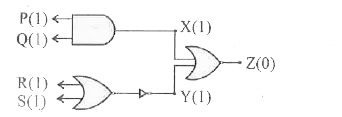
The circuit diagram shows a logic combination with the states of outputs X , Y and Z given for inputs P , Q , R and S all at state 1 . When inputs P and R change to state 0 with inputs Q and S still at 1 , the states of outputs X , Y and Z changes to
 Solution in Tamil
1, 0 , 0
1 , 1 , 1
0 , 1 , 0
0,0,1
The correct Answer is:C
Step by step video, text & image solution for The circuit diagram shows a logic combination with the states of outputs X , Y and Z given for inputs P , Q , R and S all at state 1 . When inputs P and R change to state 0 with inputs Q and S still at 1 , the states of outputs X , Y and Z changes to by Physics experts to help you in doubts & scoring excellent marks in Class 12 exams.
Updated on:21/07/2023Topper's Solved these Questions
- SEMICONDUCTOR ELECTRONICS : MATERIALS , DEVICES AND SIMPLE CIRCUITS BOOK - NEW JOYTHI PUBLICATIONCHAPTER - SEMICONDUCTOR ELECTRONICS : MATERIALS , DEVICES AND SIMPLE CIRCUITS EXERCISE - PREVIOUS YEAR QUESTIONS
3 Videos
- RAY OPTICS AND OPTICAL INSTRUMENTS BOOK - NEW JOYTHI PUBLICATIONCHAPTER - RAY OPTICS AND OPTICAL INSTRUMENTS EXERCISE - COMPETITIVE EXAM CORNER
26 Videos
- WAVE OPTICSBOOK - NEW JOYTHI PUBLICATIONCHAPTER - WAVE OPTICSEXERCISE - COMPETITIVE EXAM CORNER
17 Videos
Similar Questions
We are familiar with the semi conductors Silicon and Germanium .
a. With a necessary schematic diagram , briefly explain the characteristics of an intrinsic semiconductor.
b. Draw the energy bands of a n-type semiconductor.
c The following figure represents a
d . Draw a typically illuminated P-n junctions solar cell.
e. LED convert............ energy to light.
View SolutionA 100 W bulb produces an electric field of 2.9 V/m at a point 3m away. If the bulb is replaced by 400 W bulb without disturbing other conditions. Then the electric field produced at the same point is
View SolutionYoung's experiment is performed with light of wavelength 6000Å where in 16 frignes occupy a certain region on the screen. If 24 fringes occupy the same region with another light of wavelength λ then λ is
View SolutionThe circuit diagram (see fig.) shows a 'logic combination' with the states outputs X,Y and Z given for input P,Q,R and S all at state 1 (i.e., high). When inputs P and R change to state 0 i.e., low) with inputs Q and S still at 1 , the condition of output X,Y and Z chages to
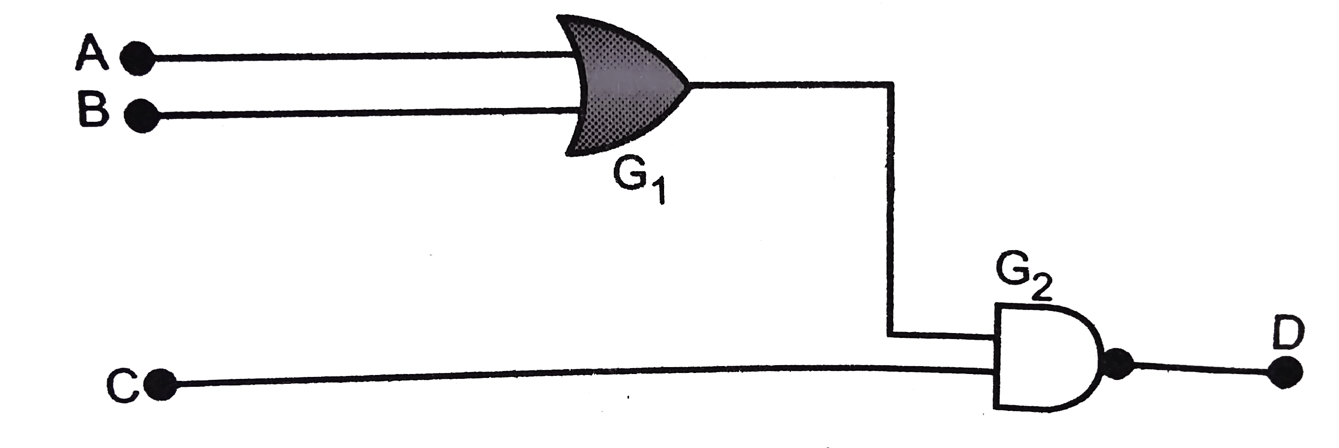
View SolutionFor the given combination of gates, if the logic states of inputs A,B,C, are as follows A=B=C=0 and A=B=1, C=0 then the logic states of output D are
View SolutionThe diagram shows a logic network. If the inputs L,M and N are all at logic 1 , what are the logic states of P,Q and R ?
View SolutionFor the given combination of gates, if the logic states of inputs A,B,C, are as follows A=B=C=0 and A=B=1,C=0 then the logic states of output D are

View SolutionLogic gates X and Y have the truth tables shown below

∣∣ ∣ ∣ ∣ ∣ ∣∣PQRPR0000110010010111∣∣ ∣ ∣ ∣ ∣ ∣∣
When the output of X of connected to the input of Y, the resulting combination is equivalent to a single.
View SolutionLogic gates X and Y have the truth tables shown below

PQRPR0000110010010111
When the output of X is connected to the input of Y, the resulting combination is equivalent to a single.
View SolutionFor the given combination of gates, if the logic states of inputs A,B,C are as follows A=B=C=-0 and A=B=1,C=0 then the logic states of output D are
View Solutionजिस लॉजिक गेट के दोनों निवेशों ( inputs ) को अवस्था 0 में रहने देने पर निर्गम (output ) 1 प्राप्त होता है , वह लॉजिक गेट है
View SolutionIn the given circuit P and Q from the inputs. The output Y is
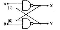
View SolutionIn the circuit shown, inputs A and B are in states '1' and '0' respectively. What is the only possible stable state of the outputs 'X' and 'Y'?
View SolutionIn the circuit shown inputs A and B are in states, 1 and 0 respectively. What is the only possible stable state of the outputs X and Y?

View SolutionA logic gate whose output will be in logic O state only when all inputs are in logic 1 state is called
View Solution
