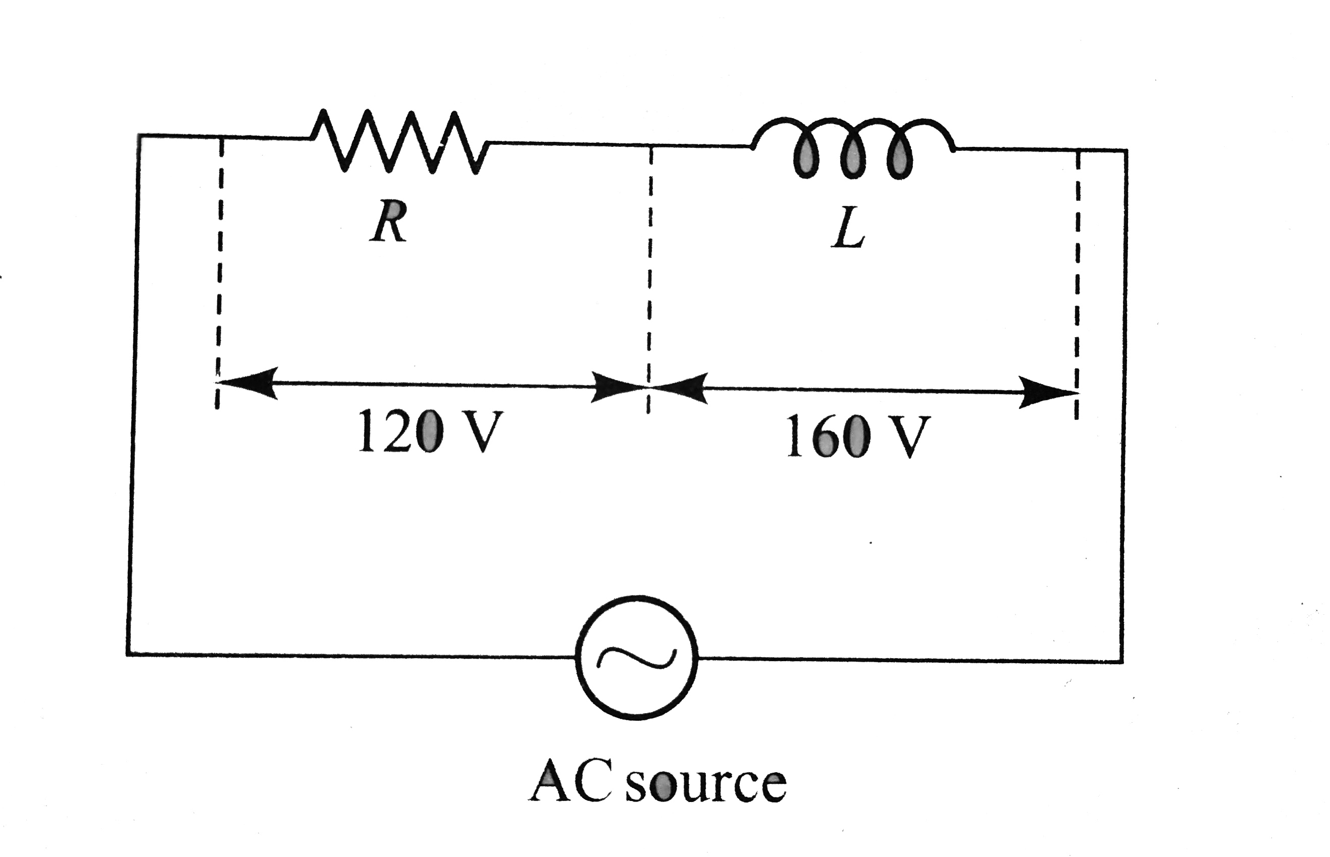
The circuit given in fig. has a resistanceless choke coil L and a resistance R. The voltage across R and L are also given in the figure. The virtual value of the applied voltage is
100V
200V
300V
400V
The correct Answer is:B
Ev=√1202+1602=200V
Topper's Solved these Questions
- ALTERNATING CURRENTBOOK - CENGAGE PHYSICS ENGLISHCHAPTER - ALTERNATING CURRENTEXERCISE - Exercises Multiple Correct
5 Videos
- ALTERNATING CURRENTBOOK - CENGAGE PHYSICS ENGLISHCHAPTER - ALTERNATING CURRENTEXERCISE - Exercises Assertion-reasoning
7 Videos
- ALTERNATING CURRENTBOOK - CENGAGE PHYSICS ENGLISHCHAPTER - ALTERNATING CURRENTEXERCISE - Exercises Subjective
15 Videos
- ATOMIC PHYSICSBOOK - CENGAGE PHYSICS ENGLISHCHAPTER - ATOMIC PHYSICSEXERCISE - ddp.4.3
15 Videos
Similar Questions
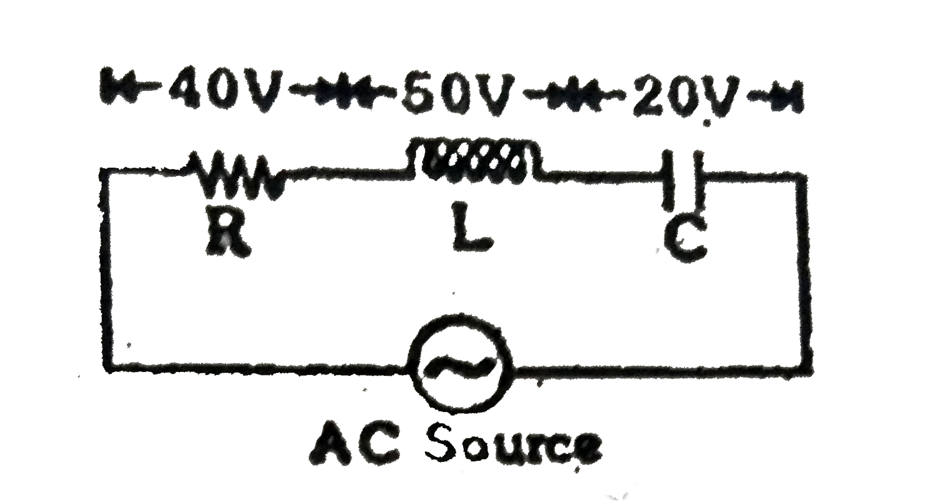
In series LCR circuit, the voltages across R, L and C are shown in the figure. The voltage of applied source
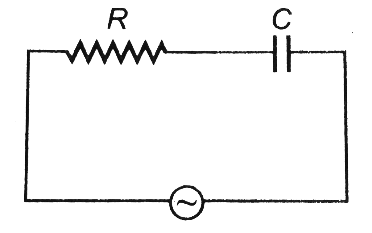
View SolutionA 50HzAC source of 20V is connected across R and C as shown in figure.
The voltage across R is 12V. The voltage across C is
View SolutionAn alternating voltage is connected in series with a resistance R and inductance L if the potential drop across the resistance is 200V and across the inductance is 150V, then the applied voltage is
View SolutionIn an a.c. circuit consisting of resistance R and inductance L, the voltage across R is 60 volt and that across L is 80 volt.The total voltage across the combination is
View SolutionA 20volts AC is applied to a circuit consisting of a resistance and a coil with negligible resistance. If the voltage across the resistance is 12V, the voltage across the coil is
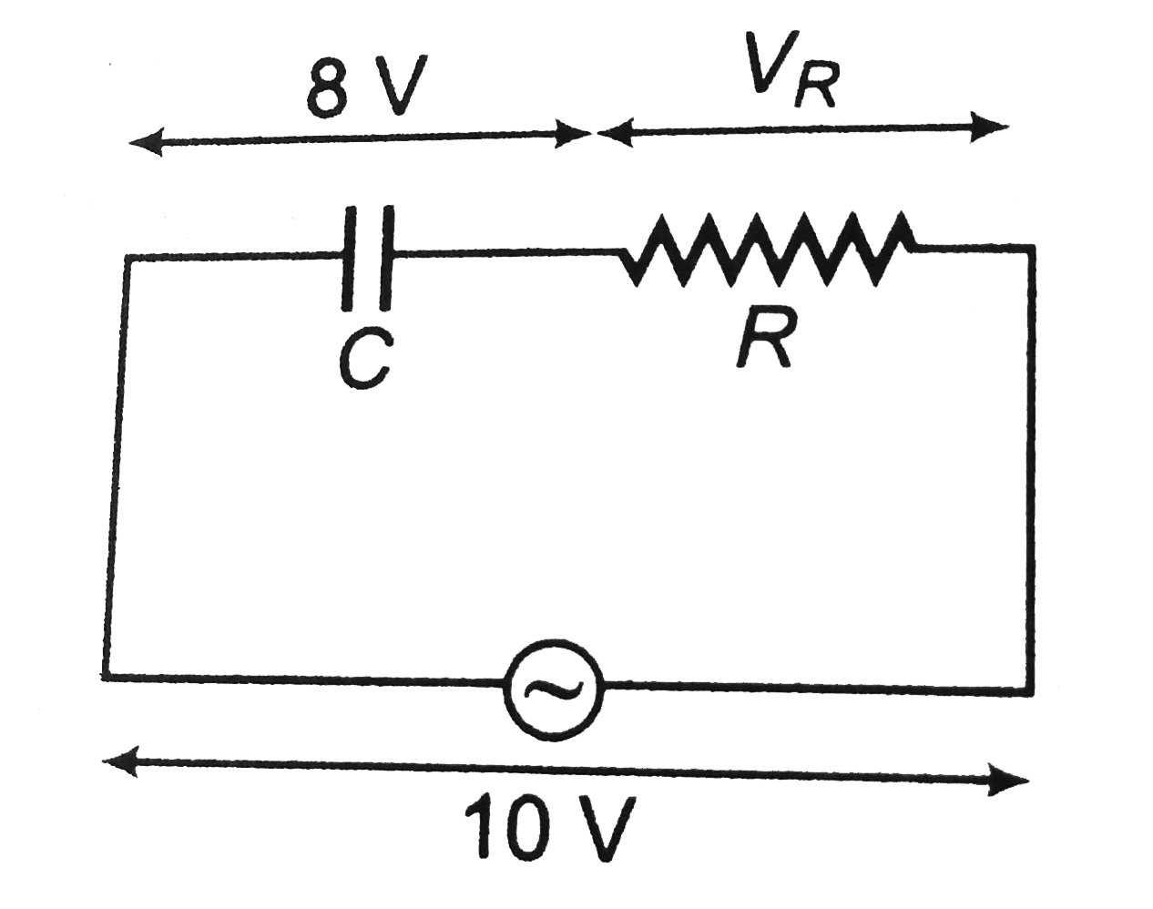
View SolutionIn a series C−R circuit shown in figureure, the applied voltage is 10V and the voltage across capacitor is found to8V. The voltage across R, and the phase difference between current and the applied voltage will respectively be
 .
.
View SolutionIn a series C−R circuit shown in figureure, the applied voltage is 10V and the voltage across capacitor is found to8V. The voltage across R, and the phase difference between current and the applied voltage will respectively be
 .
.
View SolutionIn an LCR series ac circuit the voltage across L,C and R are V1,V2 and V3 respectively The voltage of the source is .
View SolutionIn the given circuit , the voltage across the base emitter junction is
View SolutionAn AC voltage is applied acrss a series combination of L and R. If the voltage drop across the resistor and inductor are 20V and 15V respectiely, then applied peak voltage is
View Solution
