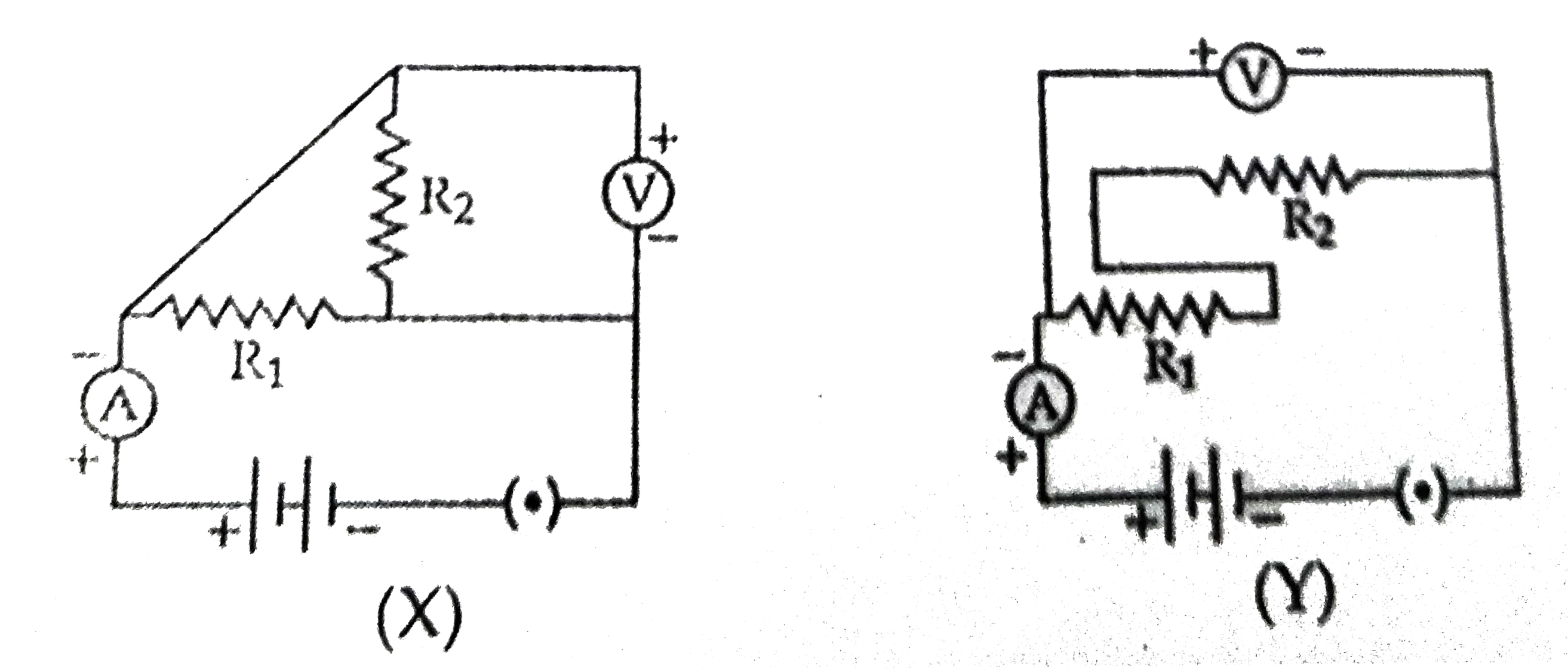
The only correct statement for the two circuits (X) and (Y) shown below is :
A
The resistors R1 and R2 have been connected in series in both the circuits
B
The resistors R1 and R2 have been connected in parallel in both the circuits
C
In the circuit (X) the resistors have been connected in parallel whereas these are connected in series in circuit (Y).
D
In the circuit (X) the resistors R1 and R2 are connected in series while these are connected in parallel in circuit (Y)
Video Solution
Text Solution
The correct Answer is:C
NA
|
Topper's Solved these Questions
- THE HUMAN EYE AND THE COLOURFUL WORLD BOOK - LAKHMIR SINGH & MANJIT KAURCHAPTER - THE HUMAN EYE AND THE COLOURFUL WORLD EXERCISE - Long Answer Type Question
3 Videos
- THE HUMAN EYE AND THE COLOURFUL WORLD BOOK - LAKHMIR SINGH & MANJIT KAURCHAPTER - THE HUMAN EYE AND THE COLOURFUL WORLD EXERCISE - NCERT Book
14 Videos
- THE HUMAN EYE AND THE COLOURFUL WORLD BOOK - LAKHMIR SINGH & MANJIT KAURCHAPTER - THE HUMAN EYE AND THE COLOURFUL WORLD EXERCISE - Long Answer Type Questions
2 Videos
- TEST PAPER 4BOOK - LAKHMIR SINGH & MANJIT KAURCHAPTER - TEST PAPER 4EXERCISE - SECTION A
10 Videos
Similar Questions
Knowledge Check
The only correct statement for the following electric circuit is :
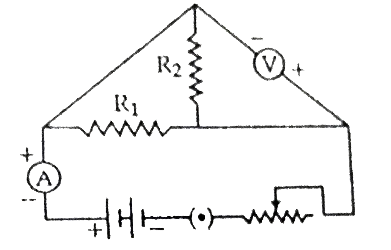 AThe voltmeter has been correctly connected in the circuitBThe Ammeter has been correctly connected in the circuitCThe Resistors R1 and R2 have been correctly connected in seriesDThe Resistors R1 and R2 have been correctly connected in parallel
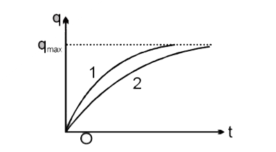 Choose the correct statement (s) related to the two circuits ABoth the capacitors are charged to the same chargeBThe emf’s of cells in both the circuit are equalCThe emf’s of the cells may be differentDThe emf E1 is more thanE2
The Boolean expression for the gate circuit shown below is
 AA+¯¯¯A=1BA+1=1CA+A=ADA+0=A
The current in the branch of a circuit shown below is

View SolutionThe power factor for the circuit shown below is
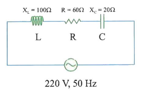
View SolutionThe power factor for the circuit shown below is

View SolutionThe inputs to the digital circuit are shown below. The output Y is
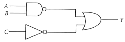
View SolutionThe Boolean expression for the gate circuit shown below is

View Solution

