Complete Solutions to Single Correct of chapter CAPACITOR AND CAPACITANCE of Class 12 book with complete answers and questions
| Class 12 | PHYSICS |
| Chapter | CAPACITOR AND CAPACITANCE |
| CENGAGE PHYSICS | Single Correct |
| Number Of Questions | 49 |
| Academic Year | 2023-24 |
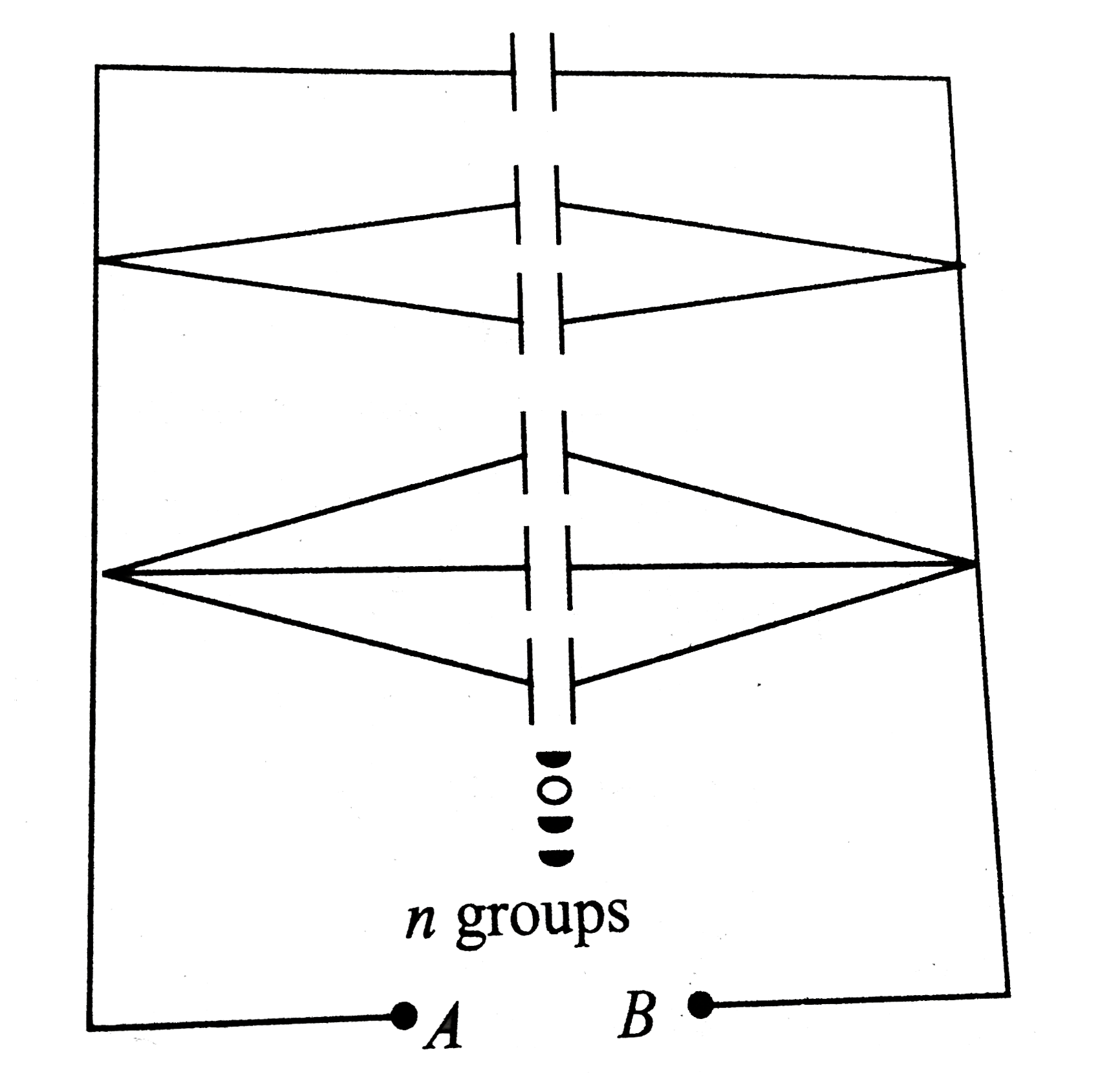
A number of capacitors, each euqal capacitance `C`, are arranged as shown in . The equialent capacitance between `A` and `B` is
 .
.
View SolutionThe plates of a parallel plate capacitor are charge upto 100 V. A 2 mm thick insulator sheet is inserted between the plates. Then to maintain the capacitor plates is increased by 1.6 mm, dielectric constant of the insulator is
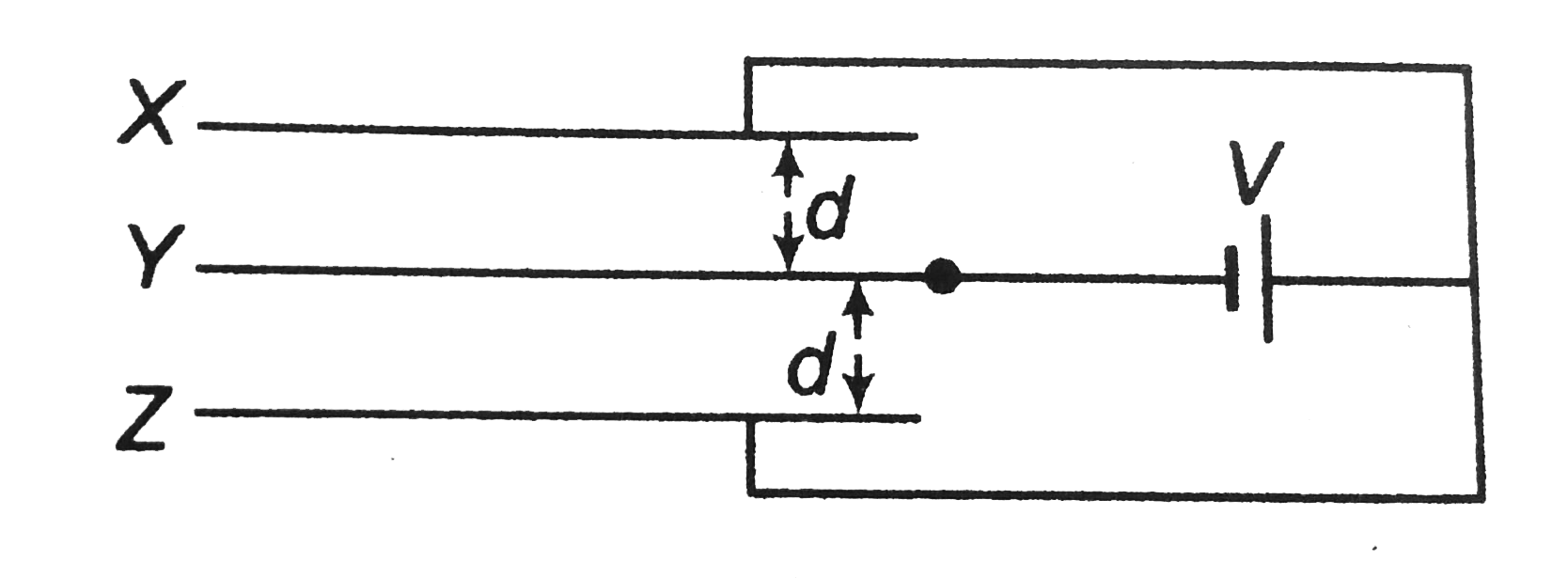
View SolutionConsider the arrangement of three plates `X,Y` and `Z` each of the area `A` and separation `d`. Find the energy stored when the plates are fully charged.
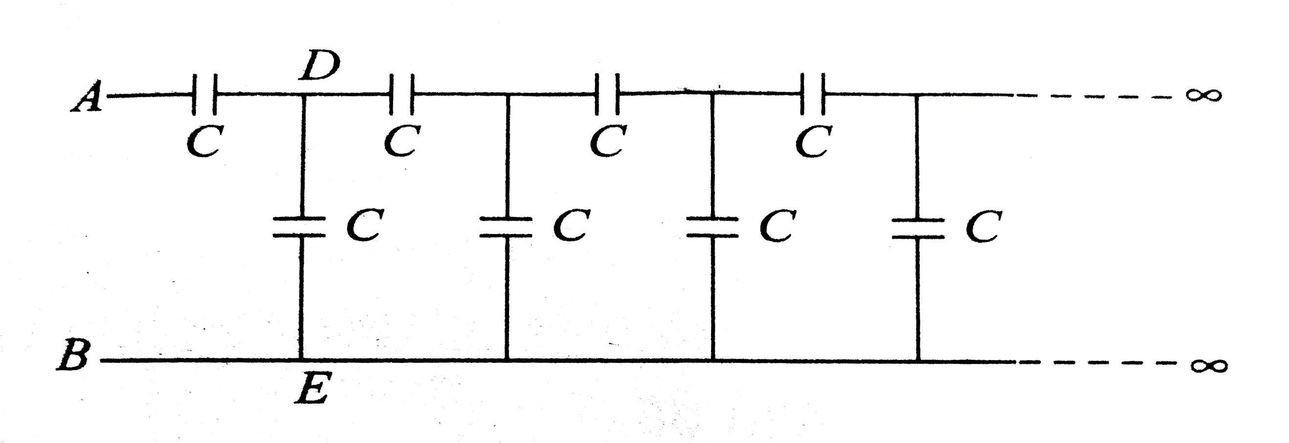
View SolutionThe equivalent capacitance of an infinite ladder of a circuit formed by the repetition of the same link consisting of identical capacitors, each with capacitance `C` , is
 .
.
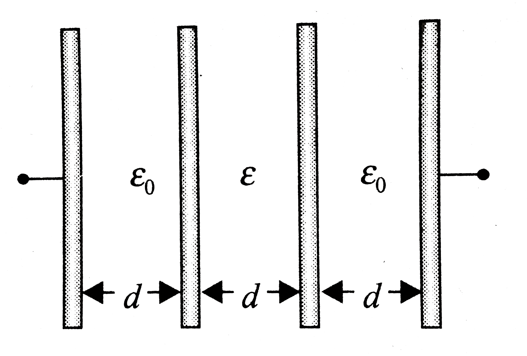
View SolutionFor the configuration, having parallel plates each of area `A`, as shown in the equivalent capacitance is .
 .
.
View SolutionA parallel plate capacitor is connected across a battery. Now, keeping the battery connected, a dielectric slab is inserted between the plates. In the process,
View SolutionSeven capacitors each of capacitance `2muF` are to be connected in a configuration to obtain an effective capacitance of `(10/11)muF`. Which of the combination (s) shown in figure will achieve the desired result?
View SolutionA sherical capacitor has an inner sphere of radius `12 cm` and an outer spere of radius `13 cm`. The outer sphere is earthed, and the inner sphere is given a charge of `2.5 muC`. The space between the concentric spjheres is filled with a liquid of dielectric caonstant `32`. Determine the potential of the inner sphere.
View SolutionA pararllel plate capacitor has plates of area `A` and separation `d` and is charged to potential diference `V`. The charging battery is then disconnected and the plates are pulle apart until their separation is `2d`. What is the work required to separate the plates?
View SolutionThe separation between the plates of a charged parallel-plate capacitor is increased. Which of the following quantities will change?
View SolutionFor section `AB` of a circuit shown in , `C_(1)=1 muF, C_(2)=2 muF, E=10 V`, and the potential difference `V_(A)-V_(B)=-10 V`. Charge on capacitor `C_(1)` is
 .
.
View SolutionA `600 pF` capacitor is charged by a `200 V` supply. It is then disconnected from the supply and is connected to another uncharged `600 pF` capacitor. What is the common potential in `V` and energy lost in `J` after reconnection?
View SolutionTwo parallel plate capacitors of capacitances C and 2C are connected in parallel and charged to a potential difference V. The battery is then disconnected and the region between the plates of the capacitor C is completely filled with a material of dielectric constant K. The potential differences across the capacitors now becomes...........
View SolutionThree capacitor `A,B`, and `C`, are connected in a circuit as shown in. What is the charge in `muC` on the capacitor `B`?
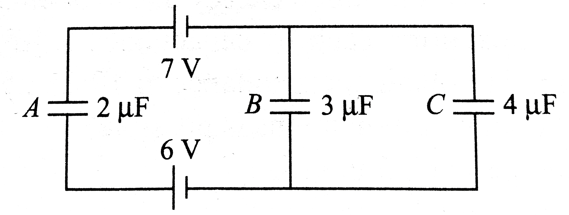 .
.
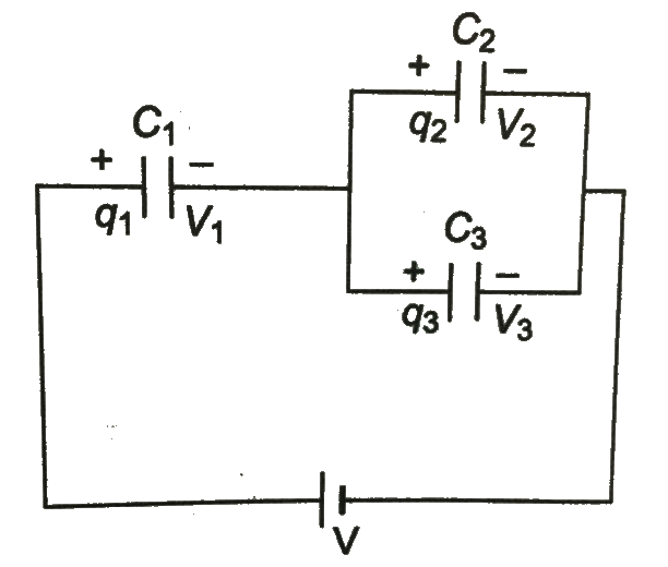
View SolutionThree capacitors are connected as shwn in. Then, the charge on capacitor `C_(1)` is .
 .
.
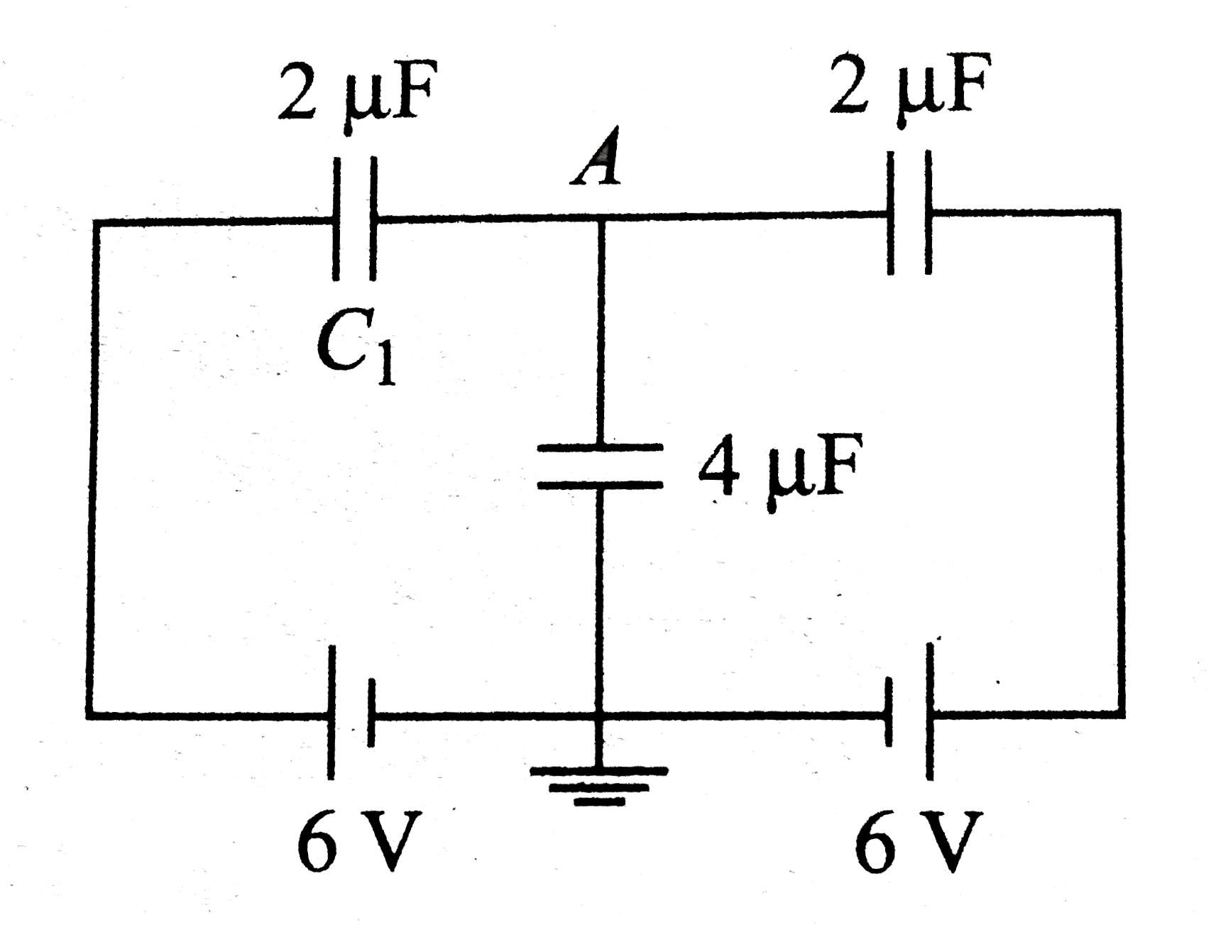
View SolutionThree capacitors are connected as shown in fig.
 .
In this question, the potential of point `A` is `
View SolutionA capacitor of capacitance `C_1 = 1.0muF` charged upto a voltage `V = 110 V` is connected in parallel to the terminals of a circuit consisting of two uncharged capacitors connected in series and possessing the capacitance `C_2 = 2.0 muF` and `C_3 = 3.0muF`. What charge will flow through the connecting wires?
View SolutionTen capacitors are joined in parallel and charged with a battery up to a potential `V`. They are then disconnected from the battery and joined in series. Then potential of the combination will be .
View SolutionIn the circuit as shown in figure if all the symbols have their usual meanings, then identify the correct statements,
 `
`
View SolutionAn uncharged parallel plate capacitor having a dielectric of dielectric constant `K` is connected to a similar air core parallel plate capacitor charged to a potential `V_(0)`. The two share the charge, and the common potential becomes `V`. The dielectric constant `K` is`
View SolutionTwo identical parallel plate capacitors are connected in series and then joined in series with a battery of `100 V`. A slab of dielectric constant `K=3` is inserted between the plates of the first capacitor. Then, the potential difference across the capacitor will be, respectively.
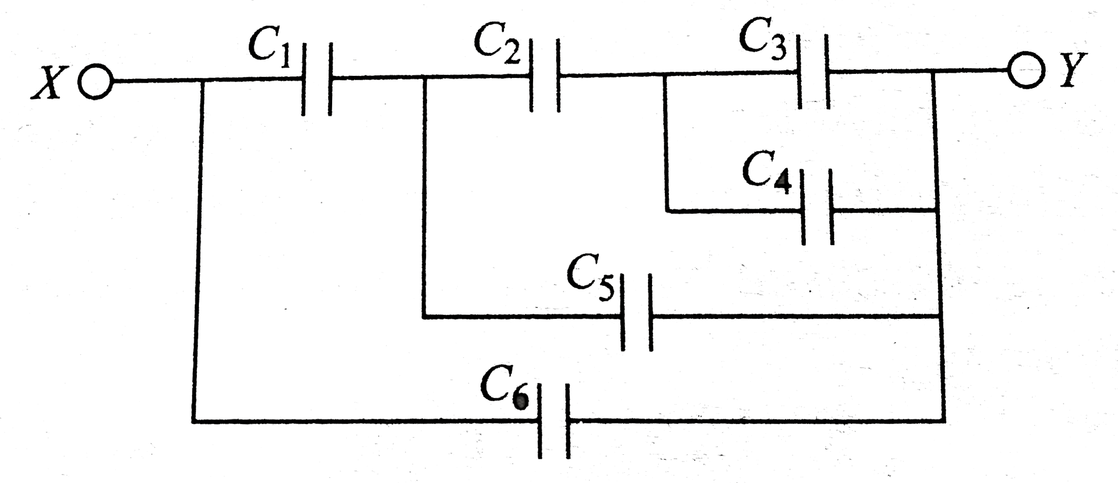
View SolutionIn the given network of capacitors as shown in, given that `C_(1) = C_(2)C_(3)=400pF`, and `C_(4)=C_(5)=C_(6)=200pF`, The effective capacitance of the circuit between `X` and `Y` is.
View SolutionThe work done in increasing the potential of a capacitor from `V` volt to `2V ` volt is `W` Then, the work done in increasing the potential of the same capacitor from `2V` volt to `4V` volt will be.
View SolutionA `5.80 muF` parallel-plate air capacitor has a plate separation of `5.00 mm` and is charged to a potential difference of `400 V`. Calculate the energy density in the region between the plates, in `J/m^3`
View SolutionThree identical capacitors, each of capacitance `C`, are connected in series with a battery of emf `V` and get fully charged. Now the battery is removed and the capacitors are cannected in parallel with positive terminals at one point and negative terminals at other point. Then, The connon potintial will be.
View SolutionIn, given `C_(1)=3 muF, C_(2)=5muF, C_(3)=9 muF`, and `C_(4)=13 muF`. What is the potential differnce between points `A` and `B`?
 .
.
View SolutionTwo condensers `C_(1) and C_(2)` in a circuit are joined as shown in figure. The potential of point A is `V_(1)` and that of B is `V_(2)`. The potential of point D will be

View SolutionA capacitor is charged with a battery and energy stored is U. After disconnecting battery another capacitor of same capacity is connected in parallel with it. Then energy stored in each capacitor is:
View SolutionConsider a disconnected plate capacitor of capacity `10 muF` with air filled in the gap between the plates. Now one-half of the space between the plates is filled with a dielectric of dielectric constant `4` as shown in .The capacity of the capacitor changes to
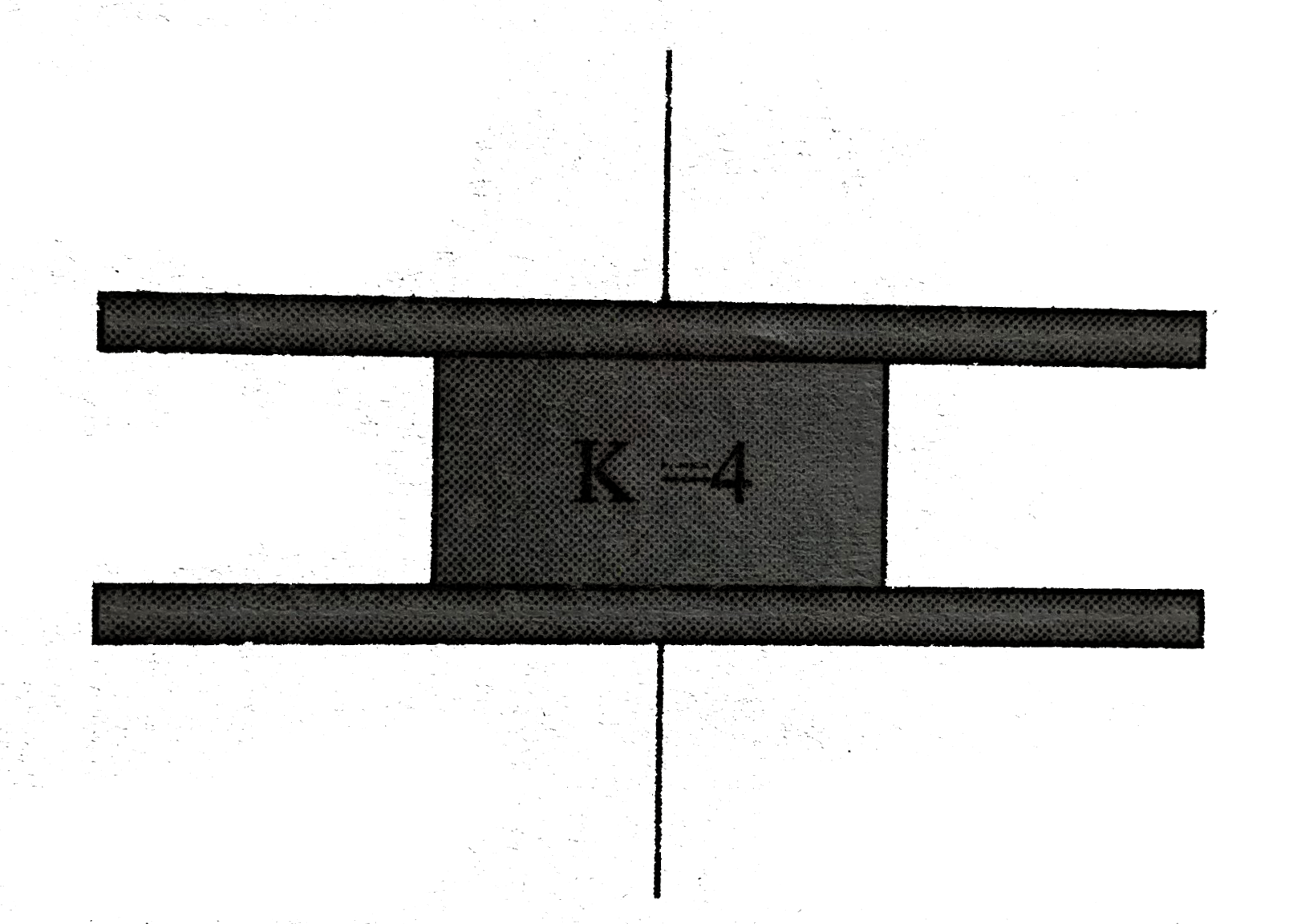 .
.
View SolutionA `2 muF` capacitor is charged to 100 V and then its plates are connected by a conducting wire. The heat produced is
View SolutionIn, the initial status of capacitors and their connections is show. Which of the folllowin is incorrect about this circuit?
 .
.
View SolutionA capacitor of capacitance `C_(0)` is charged to a patential `V_(0)` and then isolated. A small capacitor C is then charged from `C_(0)`, discharged and charge again, the process being is decreased to V. Find the value of C.
View SolutionIn the circuit shown in figure `C = 6 muF`. The charge stored in the capacitor of capacity C is

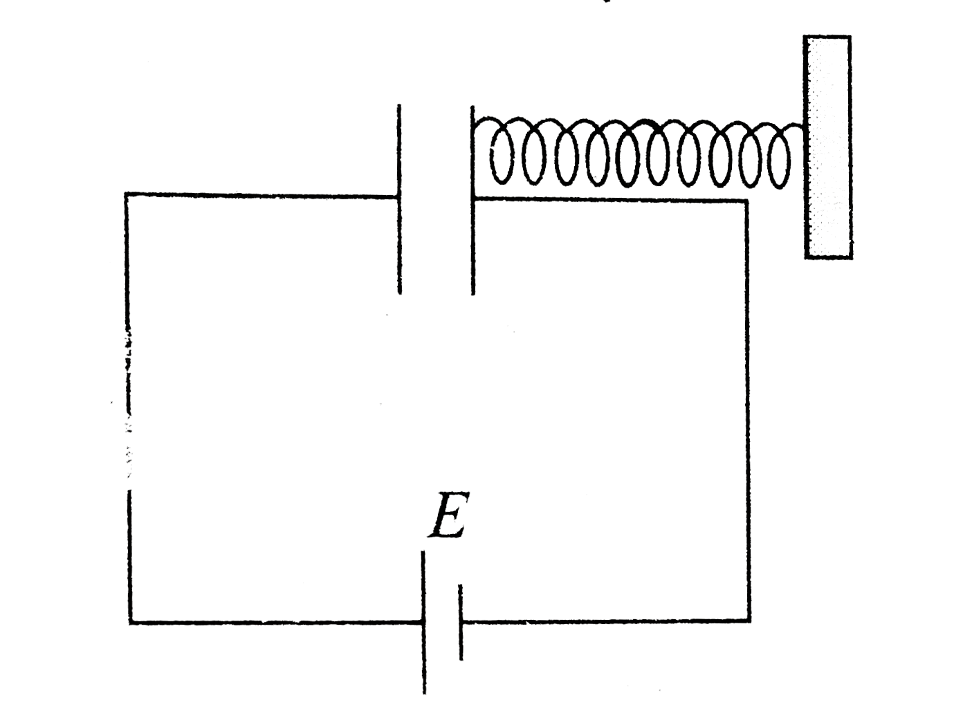
View SolutionOne plate of a capacitor is fixed, and the other is connected to a spring as shown in. Area of both the plates is `A` In strady state (equilibrium), separation between the plates is `0.8d` (spring was unstretched , and the distance between the plates was `d` when capacitor was uncharged). The force conntant of the spring is approximately.
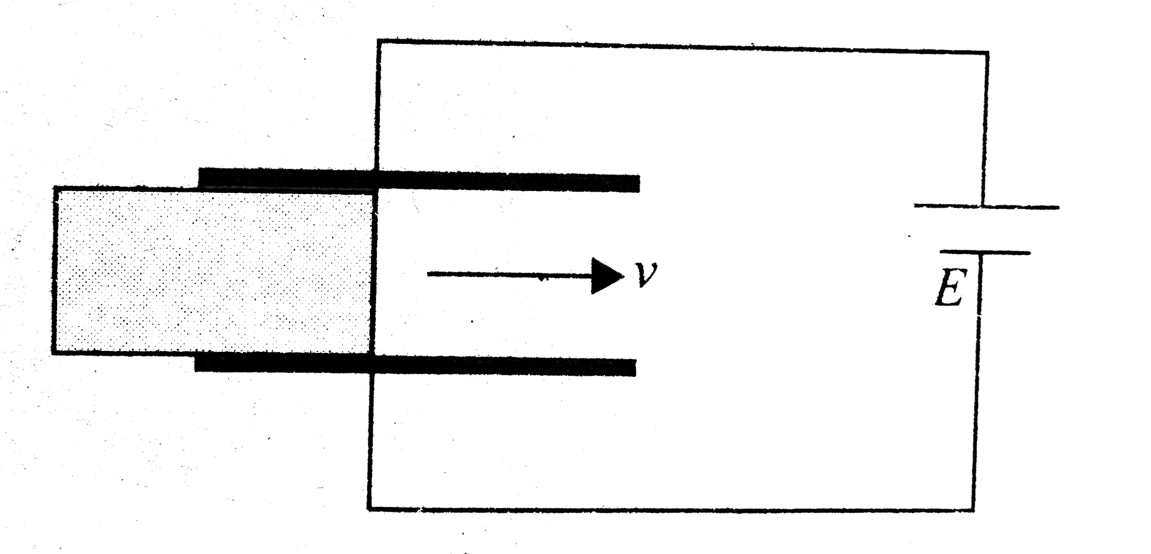
View SolutionA dielectric slab of area `A` and thickness `d` is inderted between then plates of a capaitor of area `2A` with constant speed `upsilon` as shown in. Dustance between the plates is (d).
 .
.
The capacitor is connected to a battery of emf `E`. The current in the ciruit varies with time as.
View SolutionA photographic flash unit consists of a xenon-filled tube. It givers a flash of average power `2000 W` for `0.04 s. The flash is due to discharge of a fully charged capacitor of `40 muF` The valtage to which it is charged before a flash is given by The unit is .
View SolutionTwo square plates `(lxxl)` and dielectric `(l/2xxt/2xxl)` are arranged as shown in. Find the equivalent capacitance of the structrue.
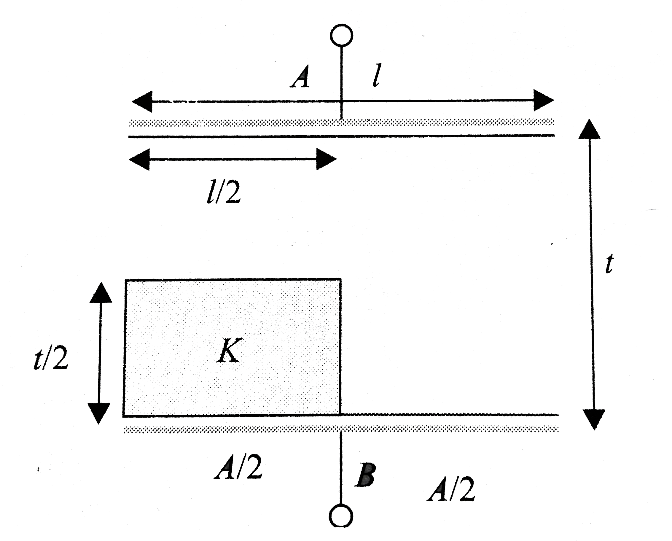 .
.
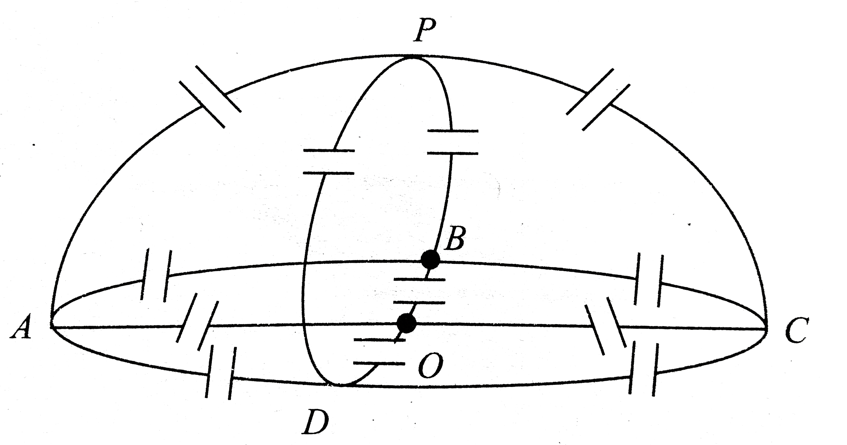
View SolutionFind the capacitance between P and O. Each capacitor has capacitance C.
 .
.
View SolutionIn the circuit shown here `C_(1)=6muF,C_(2)=3 muF` and battery B = 20 V. The switch `S`, is first closed. It is then opened and afterwards `S_(2)` is closed. What is the charge finally on `C_(2)` ?

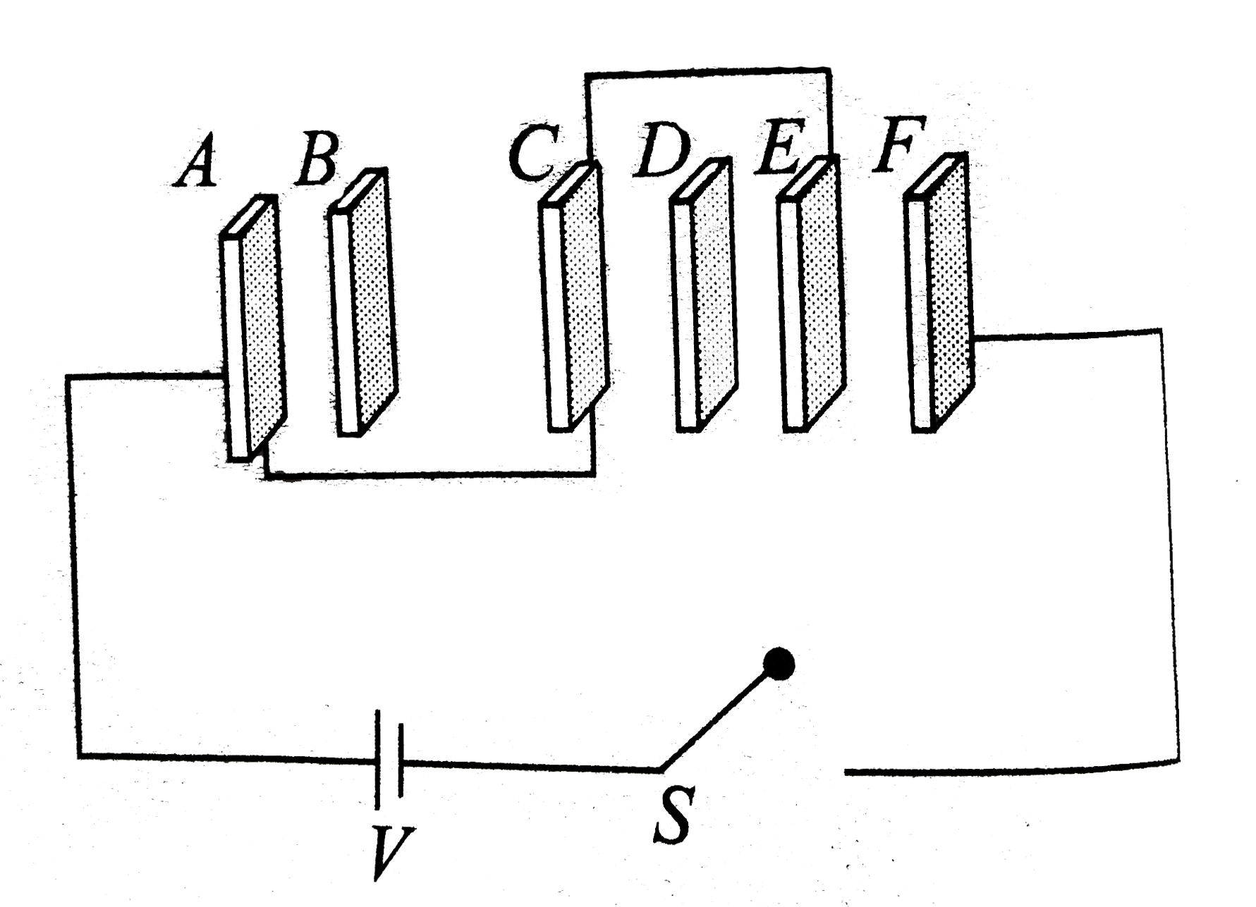
View Solution`A, B, C, D, E,` and `F` are conducting plates each of area `A`, and any two consecutive plates are separated by a distance `d`, The energy in system after the switch `S` is closed is`
 .
.
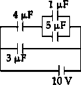
View SolutionIn the given circuit, the charge on `4 mu F` capacitor will be :
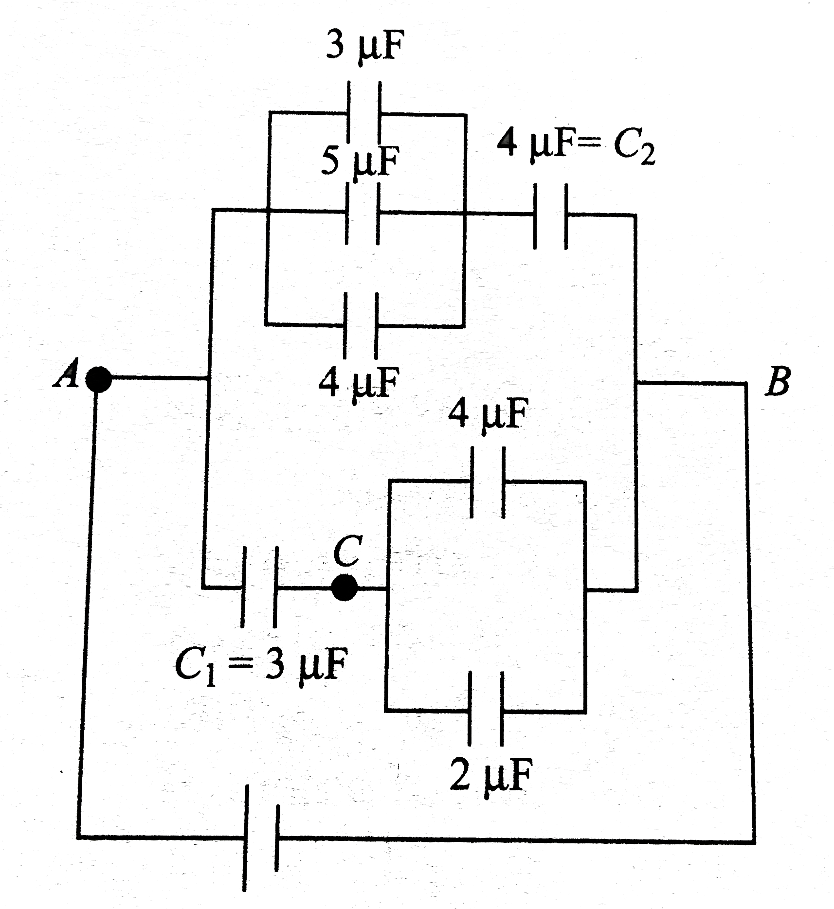
View SolutionShows a netword of seven capacitors. If the charge on the `5 muF` caacitor is `10muC`, dind the potential difference between the points `A` and `C`,
 .
.
View SolutionIn the circuit shown the effertive capacitance bewteen poits `X` and `Y` is .
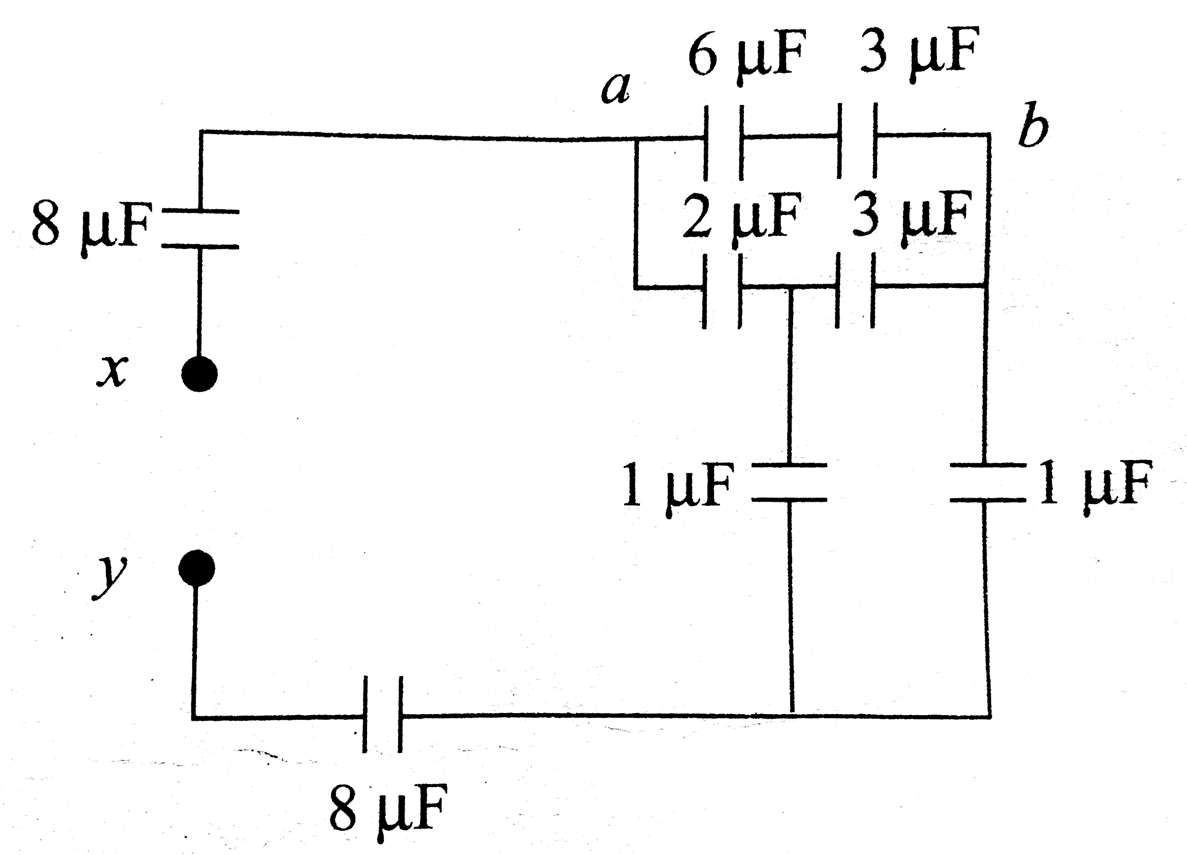 .
.
View SolutionIn figure the battery has a potential difference of `20 V`. Find
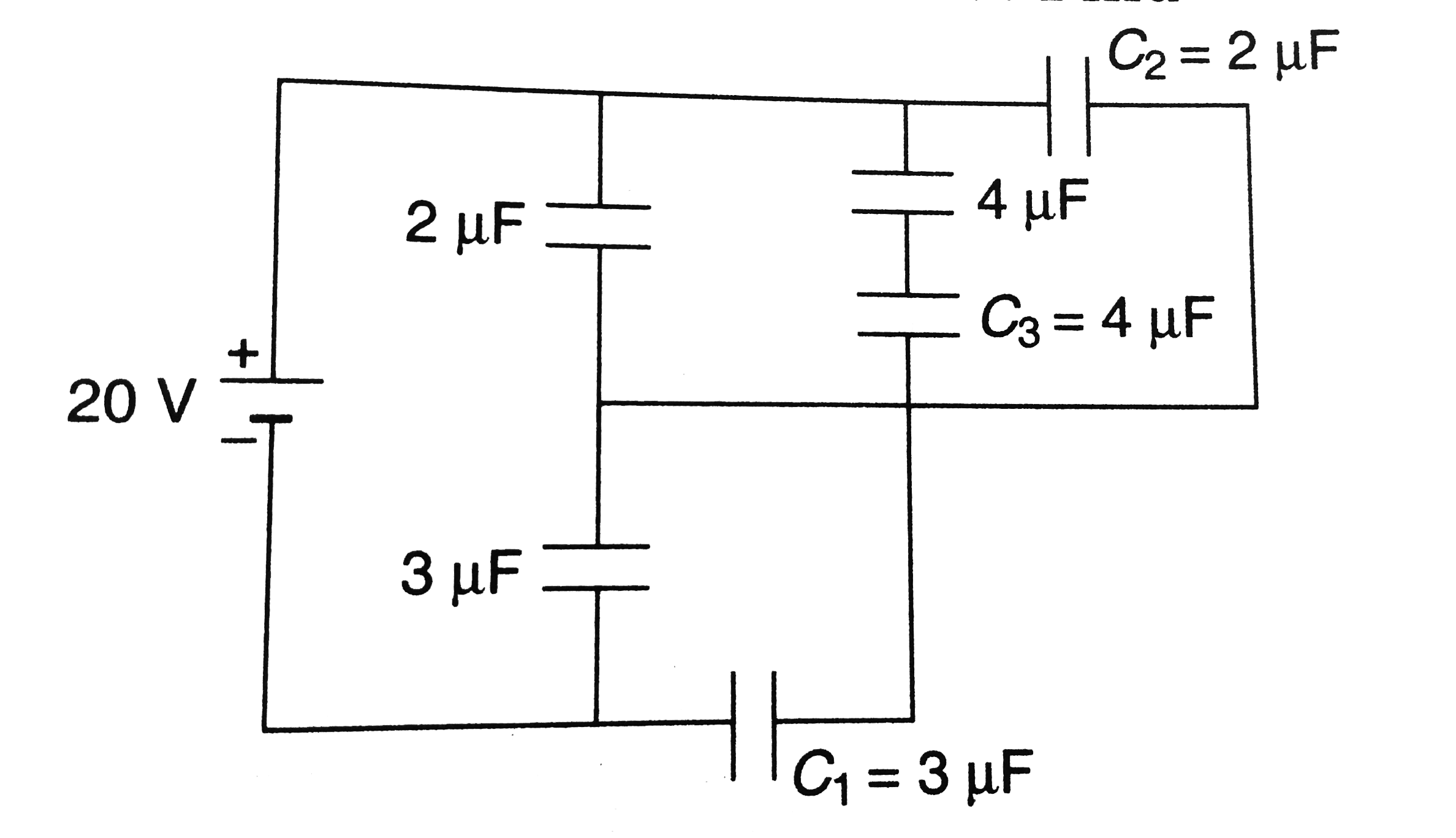
(a) the equivalent capacitance of all the capacitors across the battery and
(b) the charge stored on that, equivalent capacitance. Find the charge on
(c) capacitor 1,
(d) capacitor 2, and
(e) capacitor 3.
View SolutionIn, identical capacitors are connected in the following three configurations.
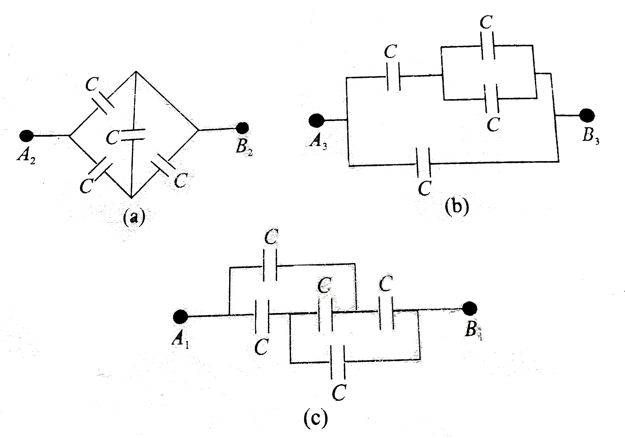 .
.
The ratio of the total capacitances in `(i),(ii)`, and `(iii)`, respectively, is .
View SolutionThe equivalent capacitance of the circuit across the terminals (A )and (B) is equal to
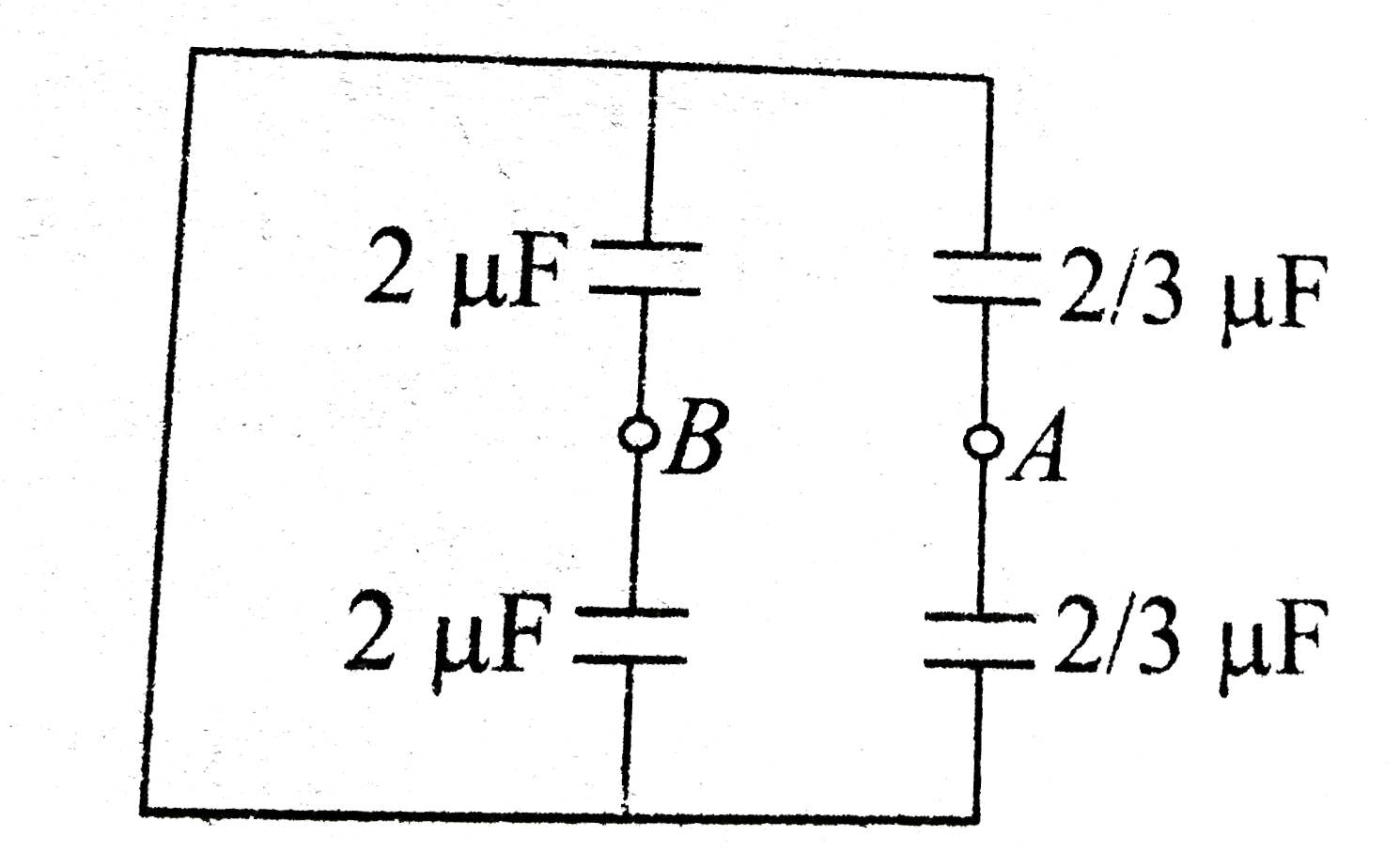 .
.
View SolutionSix capacitors each of capacitance `1 muF` are connected as show in . Find the charge flowing in direction `1` as shown in the figure will be
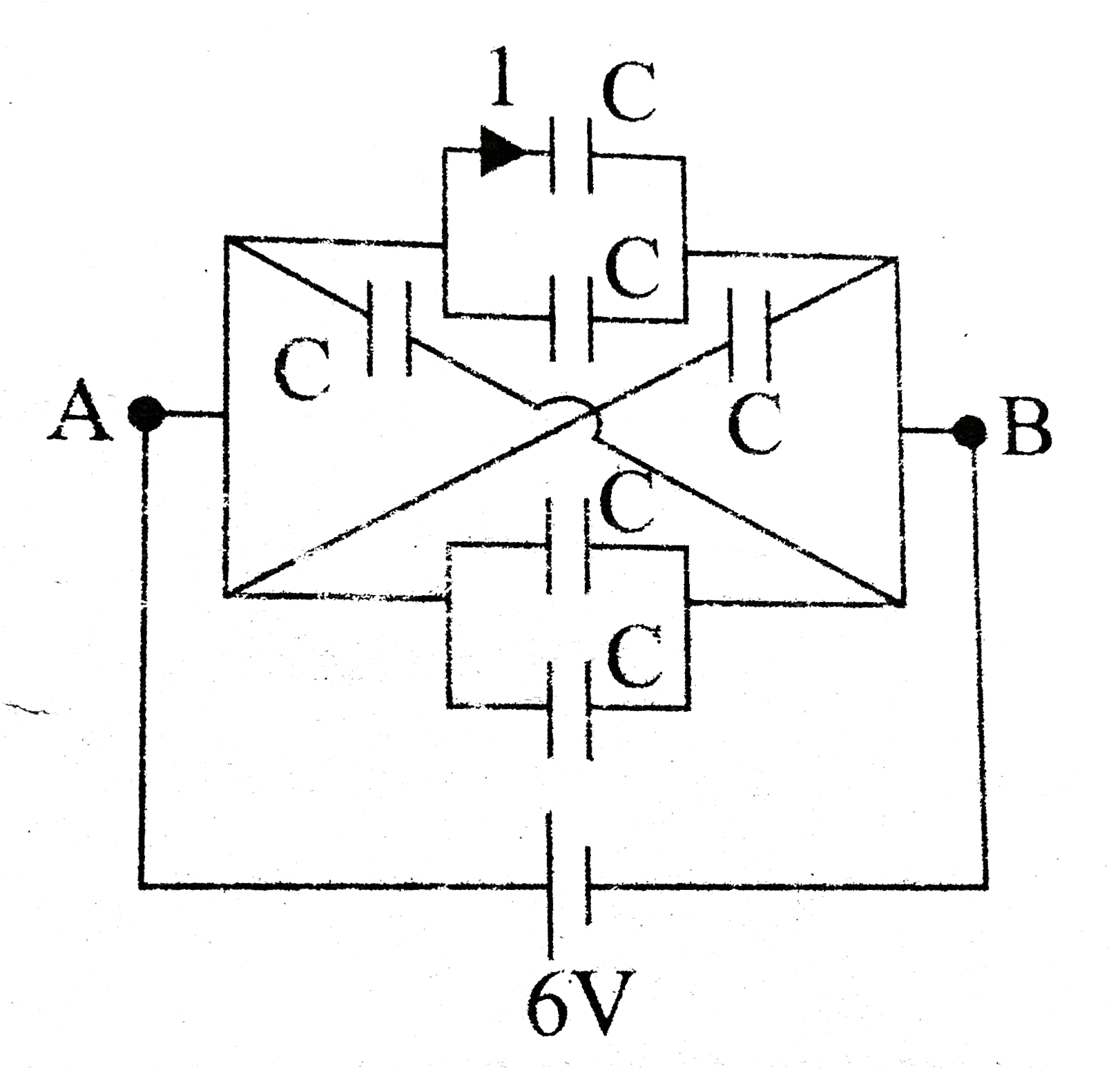 .
.
View SolutionThe equivalent capacitance between points `X and Y` in Fig. 4.182. is`
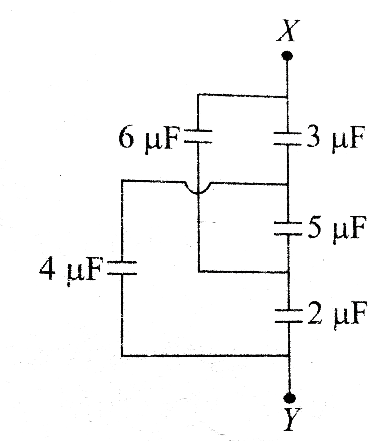 .
.
View SolutionFind the equivalent capacitance across A and B.
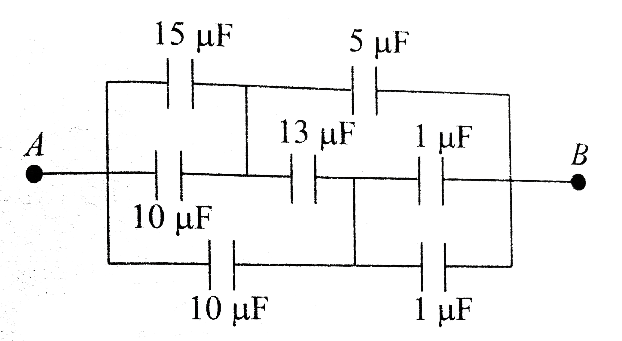 .
.
View Solution
Single Correct questions and complete solutions for chapter CAPACITOR AND CAPACITANCE of CENGAGE PHYSICS (ENGLISH) of Class 12