Complete Solutions to Illustration of chapter ELECTROMAGNETIC INDUCTION of Class 12 book with complete answers and questions
| Class 12 | PHYSICS |
| Chapter | ELECTROMAGNETIC INDUCTION |
| CENGAGE PHYSICS | Illustration |
| Number Of Questions | 19 |
| Academic Year | 2023-24 |
A long solenoid with radius `2cm` carries a current of `2A`. The solenoid is `70cm` long and is composed of `300` turns of wire. Assuming ideal solenoid model, calculate the flux linked with a circular surface if
(a) it has a radius of `1cm` and is perpendicular to the axis of the solenoid:
(i) inside,
(ii) outside.
(b)it has a radius of `3cm` and is perpendicular to the axis of the solenoid with its center lying on the axis of the solenoid.
( c ) it has a radius greater than `2cm` and axis of the solenoid subtend an angle of `60^(@)` with the normal to the area (the center of the circular surface being on the axis of the solenoid).
(d) the plane of the circular area is parallel to the axis of the solenoid.
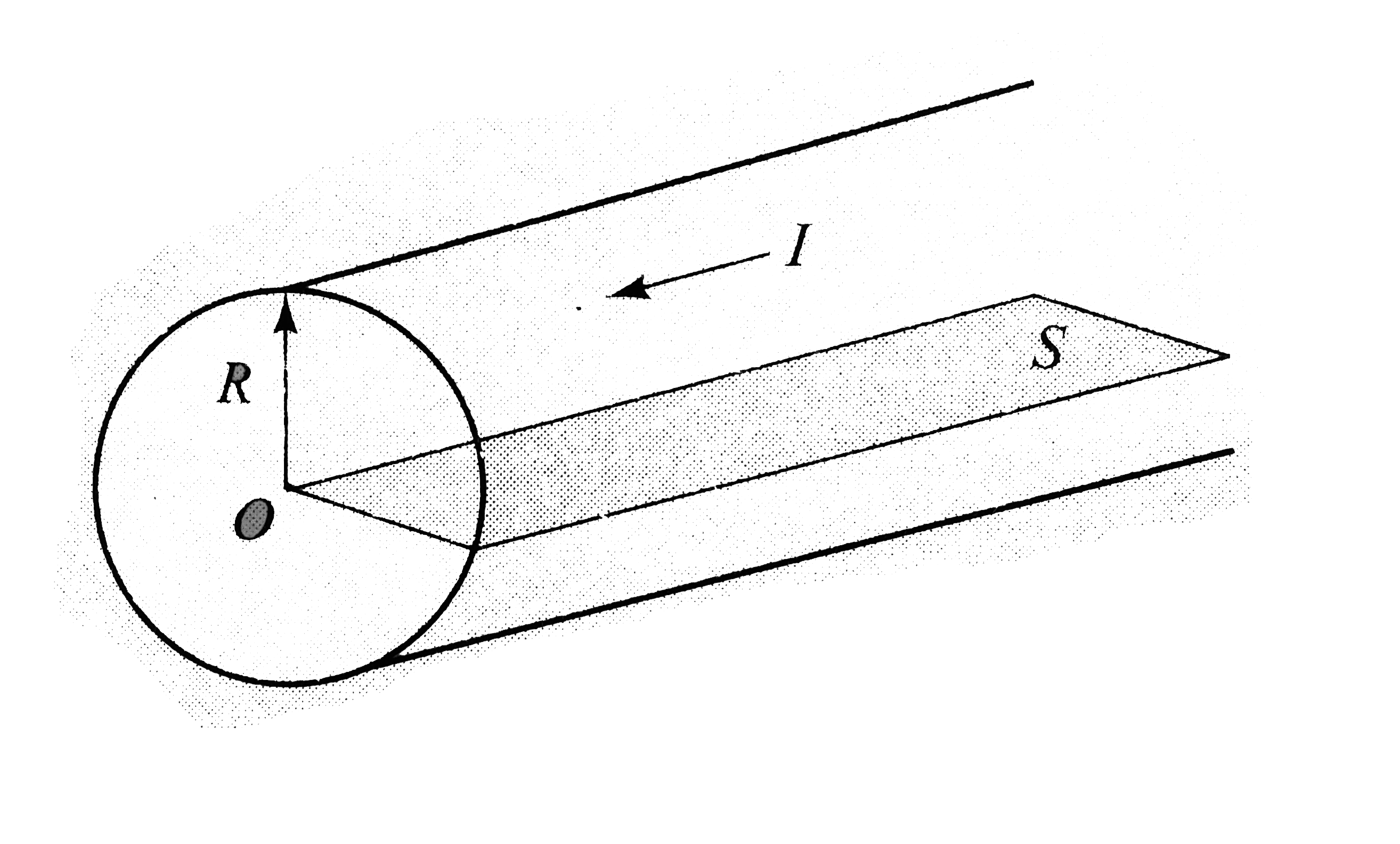
View SolutionA long copper wire carries a current of `I` ampere. Calculate the magnetic flux per meter of the wire for a plane surface `S` inside the wire as shown in Fig.
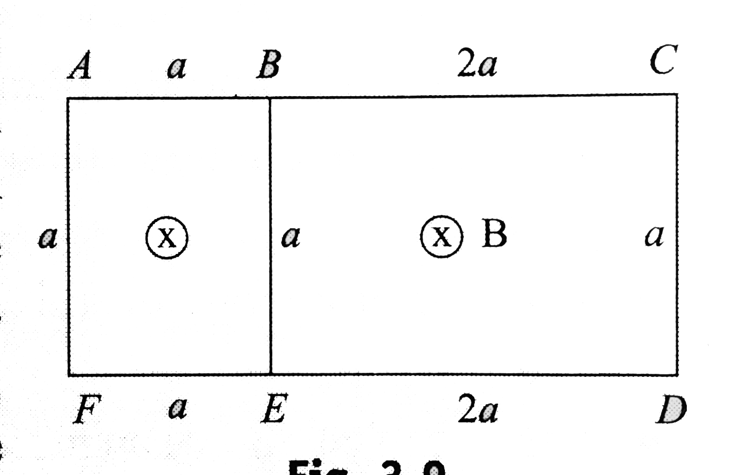
View SolutionA closed loop with the geometry shown in Fig. 3.9 is placed in a uniform magnetic field direction into the plane of the paper. If the magnetic field decreases with time, determine the direction of the induced emf in this loop.
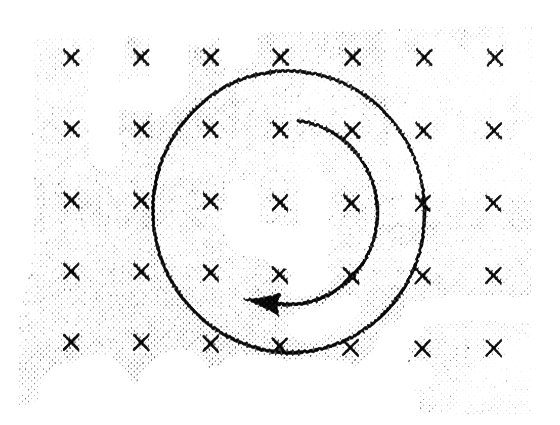
View SolutionA circular loop of radius a having `n` turns is kept in a horizontal plane. A uniform magnetic field `B` exists in a vertical direction as shown in Fig.313. Find the emf induced in the loop if the loop is roated with a uniform angualr velocity `omega` about
(a) an axis passing through the center and perendicular to the plane of the loop.
(b) the diameter.
View SolutionFigure 3.15(a) shown two circular rings of radii `a` and `b` `(a gt b)` joined together with wires of negligible resistance. Figure 3.15(b) shown thew pattern obtained by folding the small loop in the plane of the large loop.
(a)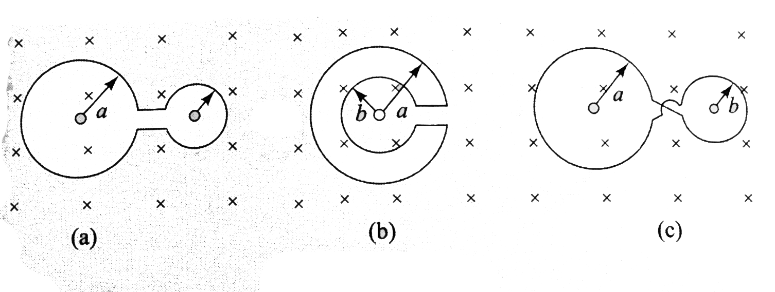
The pattern shown in Fig.3.15( c ) is obtained by twisting the small loop of Fig.3.15(a) through `180^(@)`.
All the three arrangement are placed in a uniform time varying magnetic field `dB//dt = k`, perpendicular to the plane of the loops. if the resistance per unit length of the wire is `lambda`, then determine the induced current in each case.
View SolutionSpace is divided by the line AD into two regions. Region I is field free and the Region II has a unifrom magnetic field B direction into the plane of the paper. ACD is a simicircular conducting loop of radius r with center at O, hte plane of the loop being in the plane of the paper. The loop is now made to rotate with a constant angular velocity `omega` about an axis passing through O and the perpendicular to the plane of the paper. The effective resistance of the loop is R.
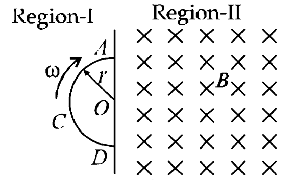
(i) obtain an expression for hte magnitude of the induced cureent in the loop.
(ii) Show the direction of the current when the loop is entering into the Rigion II.
Plot a graph between the induced e.m.f and the time of roation for two periods or rotation.
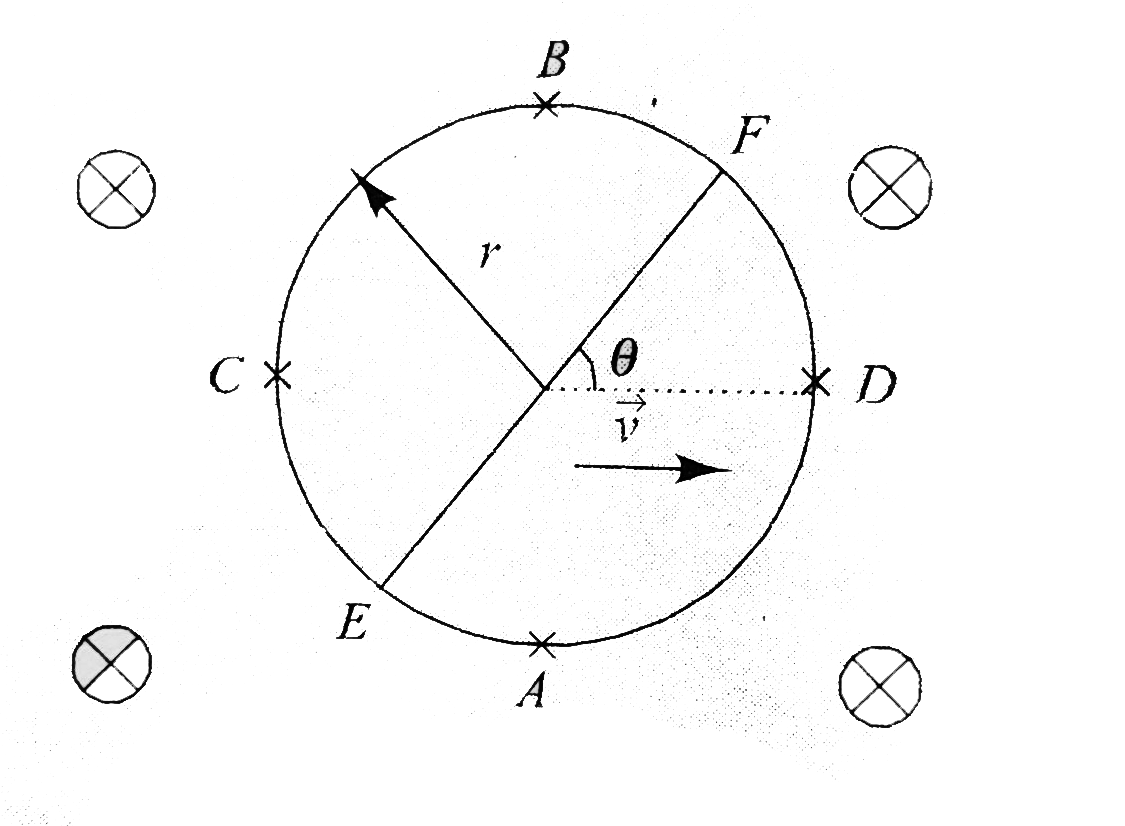
View SolutionA circular loop of radius `r` moves with a constant velocity `v` in a region with uniform magnetic field `B`. Calculate the potential difference between two points `(A, B)`, `(C, D)`, and `(E, F)` located on the loop.
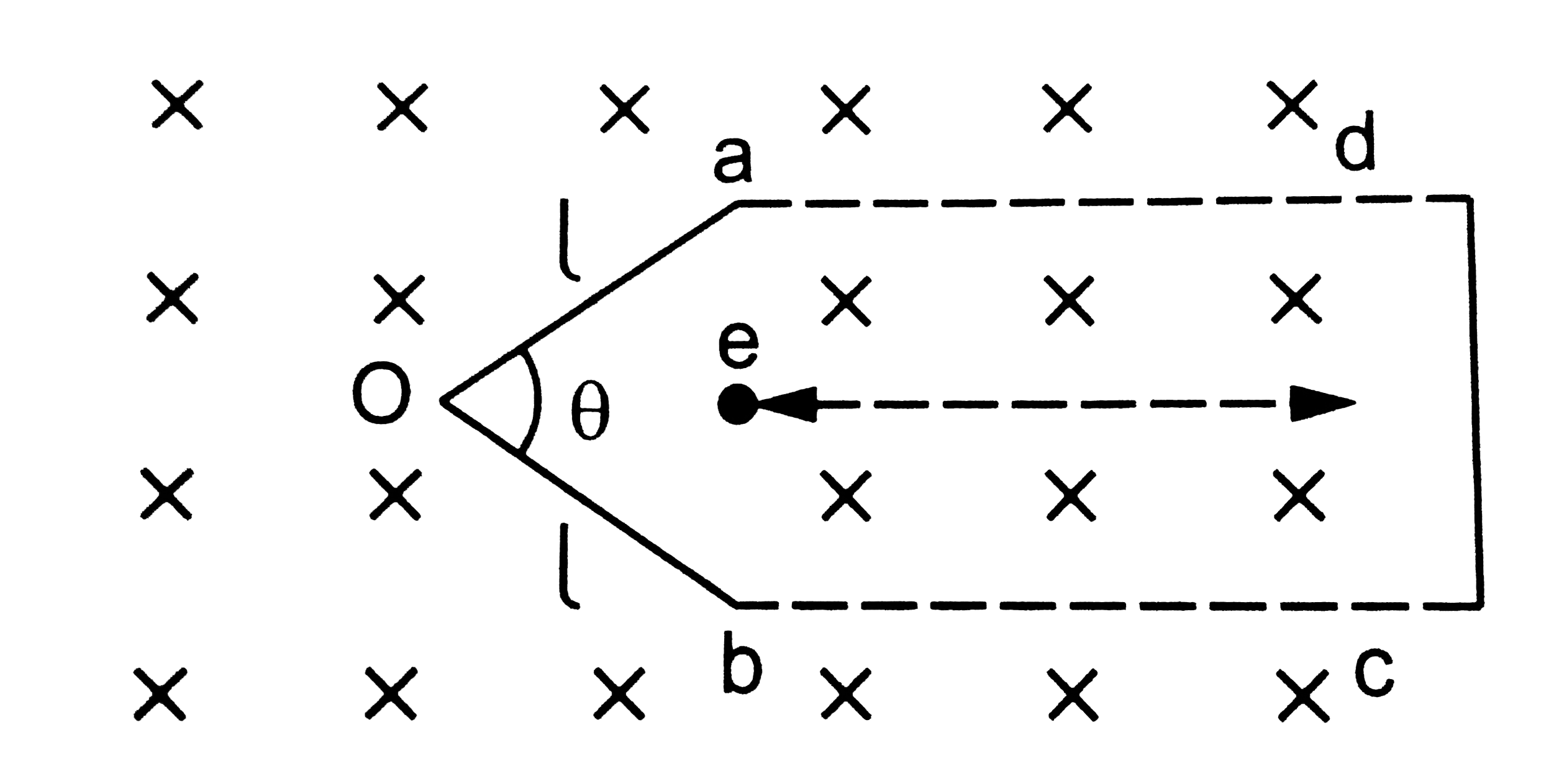
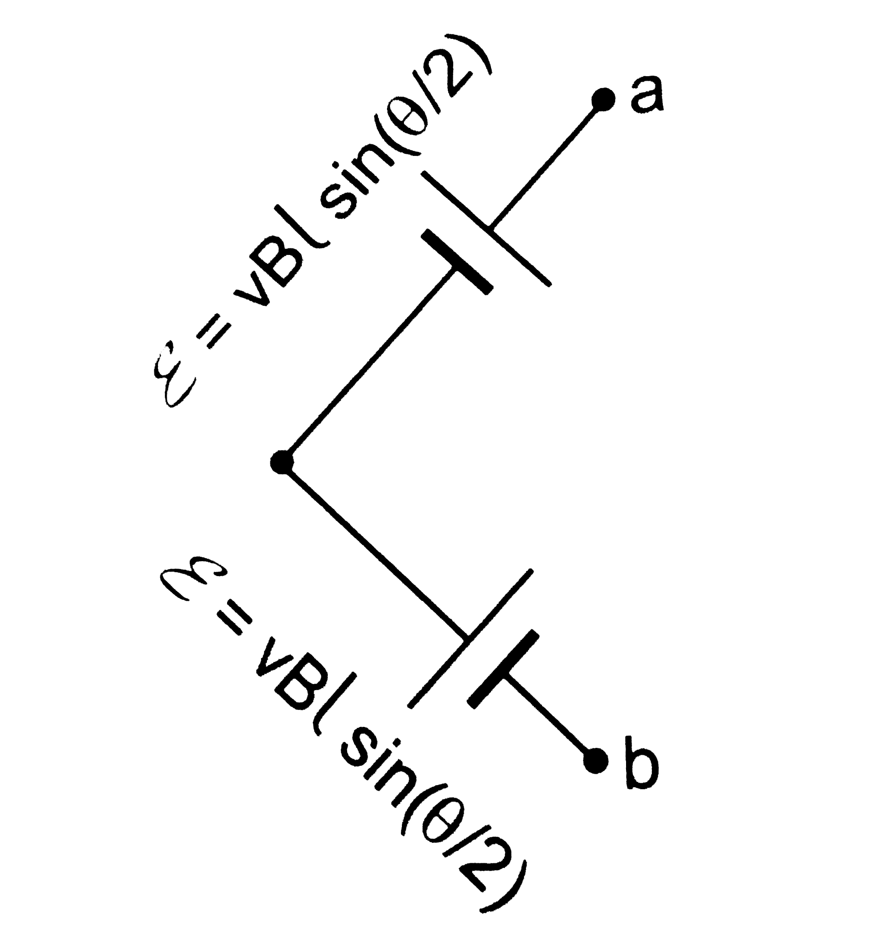
View SolutionAn angle aob made of a conducting wire moves along its bisector through a magnetic field B as suggested by figure. Find the emf induced between the two free ends if the magnetic field is perpendicular ot the plane of the angle.
View SolutionA conducting rod of length `l` slides at constant velocity `v` on two parallel conducting rails, placed in a uniform and constant magnetic field `B` perpendicular to the plane of the rails as shown in Fig.3.49. A resistance `R` is connected between the two ends of the rails.
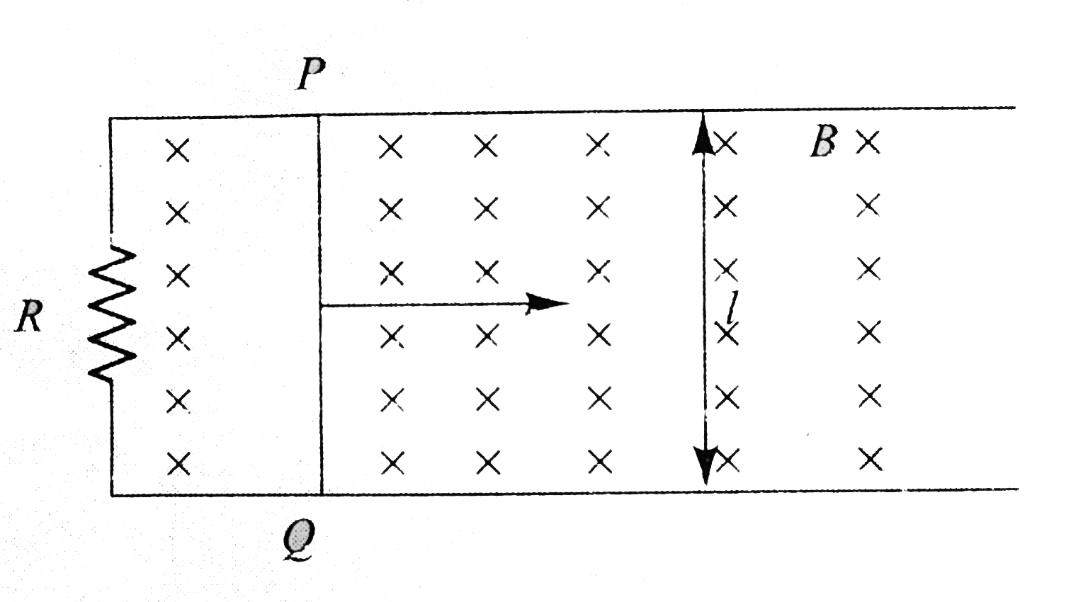
(a) Idenify the cause which produces change in magnetic flux.
(b) Identify the direction of current in the loop.
( c) Determine the emf induced in the loop.
(d) Compute the electric power dissipated in the resistor.
(e) Calcualte the mechenical power required to pull the rod at a cinstant velovity.
View SolutionTwo long parallel horizontal rails a, a distance d aprt and each having a risistance `lambda` per unit length are joing at one end by a resistance R. A perfectly conduction rod MN of mass m is free to slide along the rails without friction (see figure). There is a uniform magnetic field of induction B normal to the plane of the paper and directed into the paper. A variable force F is applied to the rod MN such that, as the rod moves a constant current flows through R.
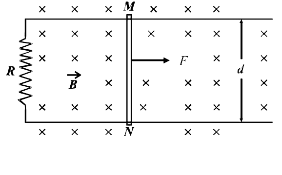
(i) Find the velocity of the rod and the applied force F as function of the distance x of the rod from R.
(ii) What fraction of the work done per second by F is converted into heat?
View SolutionA metal rod `1.5m` long rotates about its one end in a vertical plane at right angles to the magnetic meridian. If the frequency of rotation is `20 rev s^(-1)`, find the emf induced between the ends of the rod `(B_(H) = 0.32G)`.
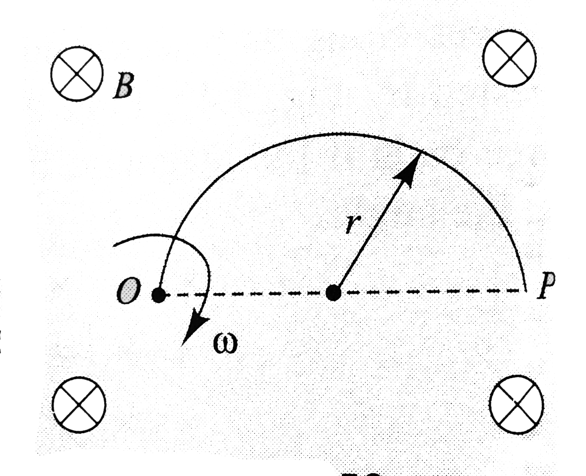
View SolutionA wire is in the form of a semicircle of radius `r`. One end is attached to an axis about which it rotates with an angular speed `omega`. The axis is normal to the plane of the semicircle. The wire is immersed in a uniform magnetic field `B` parallel to the axis. find the induced emf between points `o` and `P` of the semicircle.
View SolutionA metal disc of radius `R = 25 cm` rotates with a constant angular velocity `omega = `130` rad `s^(-1)` about its axis. Find the potential difference between the center and rim of the disc if
(a) the external magnetic field is absent,
(b) the external uniform megnetic field `B = 5.0`mT directed perpendicular to the disc.
View SolutionA copper rod of length `0.19m` is moving with uniform velocity `10ms^(-1)` parallel to a long straight wire carrying a current of `5.0A`. The rod is perpendicular to the wire with its ends at distances `0.01` and `0.2m` from it. Calculate the emf induced in the rod.
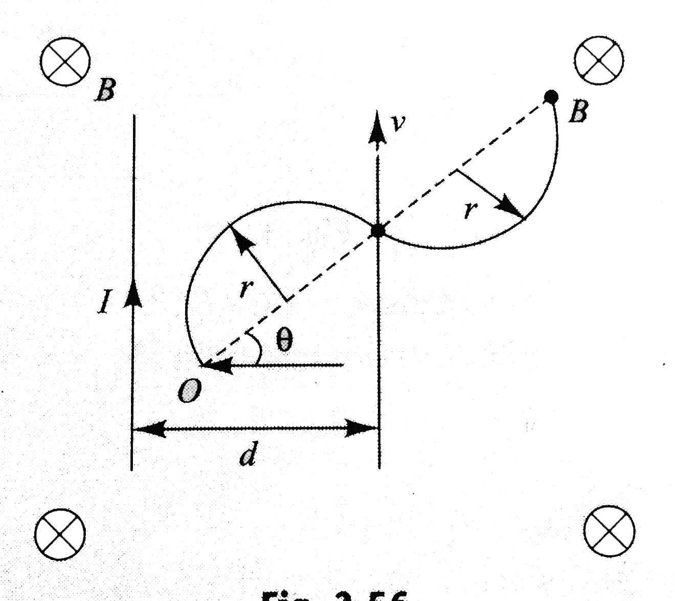
View SolutionAn infinite wire carries a current `I`. An S- shaped conducting rod of two semicircles esch of radius `r` is placed at an angle `theta` to the wire. The center of the conductor is at a distance `d` from the wire. If the rod translates parallel to the wire with a velocity `v` as shown in Fig. .3.56, calculate the emf induced across the ends `Ob` of the rod.
View SolutionA thin non-conducting ring of mass `m` carrying a charge `q` can freely rotate about its axis. At the initial moment, the ring was at rest and no magnetic field was present. Then a uniform magnetic field was switched on, which was perpendicular to the plane of the ring and increased with time according to a certain law: `(dB)/(dt) = k`.
Find the angular velocity `omega` of the ring as a function of `k`.
View SolutionA thin non-conducting ring of mass `m` carrying a charge `q` can freely rotate about its axis. At `t = 0`, the ring was at rest and no magnetic field was present. Then suddenly a magnetic field `B` was set perpendicular to the plane. Find the angular velocity acquired by the ring.
View SolutionA non-conducting ring of mass `m` and radius `R` has a charge `Q` uniformly distributed over its circumference. The ring is placed on a rough horizontal surface such that plane of the ring is parallel to the surface. A vertical magnetic field `B = B_0t^2` tesla is switched on. After 2 a from switching on the magnetic field the ring is just about to rotate about vertical axis through its centre.
(a) Find friction coefficient `mu` between the ring and the surface.
(b) If magnetic field is switched off after `4 s`, then find the angle rotated by the ring before coming to stop after switching off the magnetic field.
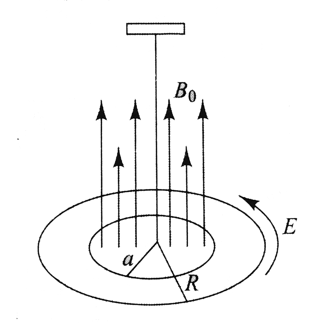
View SolutionA line charge with linear charge density `lambda` is wound around an insulating disc of mass `M` and radius `R`, which is then suspended horizontally as shown in Fig. 3.90, so that it is free to rotate. In the central region, of radius `a`, there is a uniform magnetic field `B_(0)`, pointing up. Now the magnetic field is switched off, which causes the disc to rotate.
Find the angular speed with which the disc starts rotating.
View Solution
Illustration questions and complete solutions for chapter ELECTROMAGNETIC INDUCTION of CENGAGE PHYSICS (HINGLISH) of Class 12
All Exercises from CENGAGE PHYSICS Class 12 PHYSICS ELECTROMAGNETIC INDUCTION
- Archives Asserton - Reasoning
- Archives Fill In The Blanks
- Archives Multiple Correct
- Archives Single Correct
- comprehensive
- comprehensive type
- compression type
- Exercise 3.1
- Exercise 3.2
- Exercises Asserton - Reasoning
- Exercises Integer
- Exercises Linked Comprehension
- Exercises Multiple Correct
- Exercises Single Correct
- Exercises Subjective
- Illustration
- Multiple correct Answer Type
- single correct
- single correct
- single correct answer
- Single Correct Answer Type
- Solved Example