Complete Solutions to Level 2 Single Correct of chapter ELECTROMAGNETIC INDUCTION of Class 12 book with complete answers and questions
| Class 12 | PHYSICS |
| Chapter | ELECTROMAGNETIC INDUCTION |
| DC PANDEY | Level 2 Single Correct |
| Number Of Questions | 37 |
| Academic Year | 2023-24 |
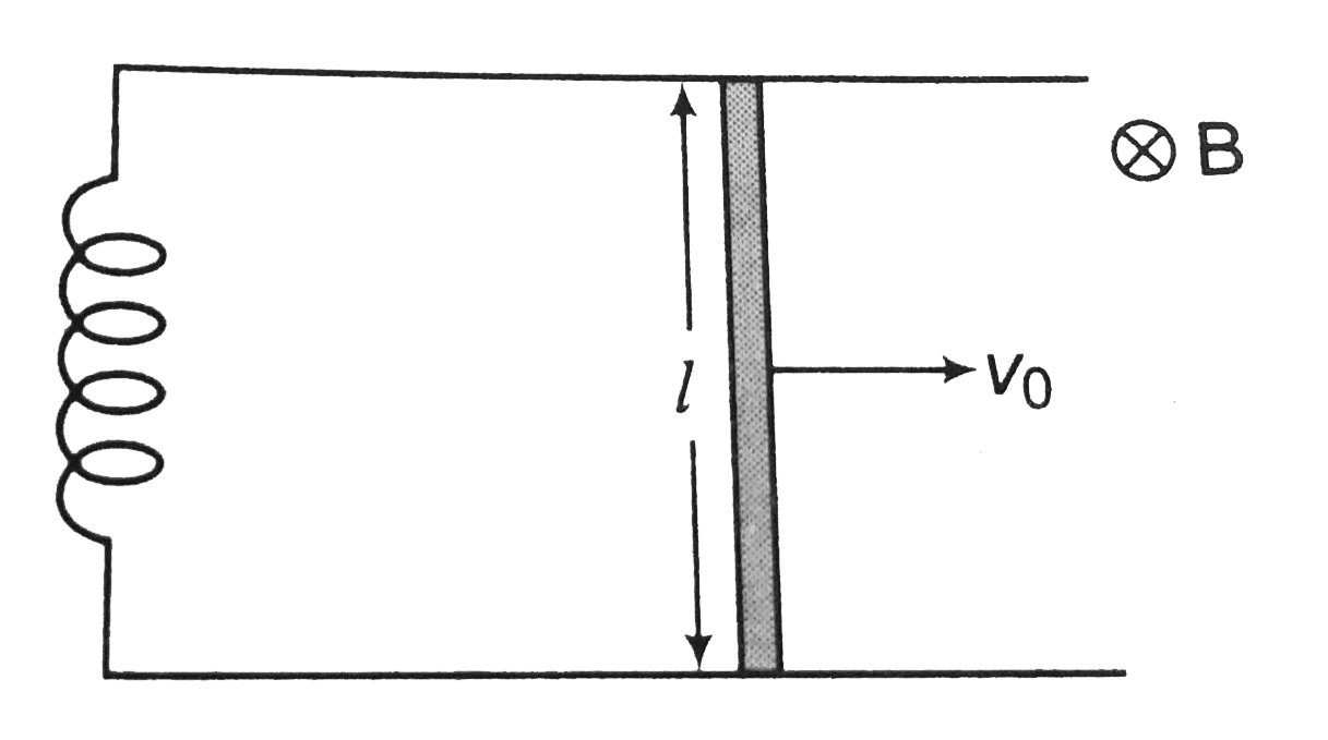
Two ends of an inductor of inductance `L` are connected to two parallel conducting wires. A rod of length `l` and mass m is gien velocity `v_0` as shown. The whole sytem is placed in perpendicular magnetic field B. Find the maximum current in the inductor. (Neglect gravity and friction)
View SolutionA conducting rod is moving with a constant velocity v over the parallel conducting rails which are connected at the ends through a resistor R and capacitor C as shown in the figure. Magnetic field B is into the plane. Consider the following statements.
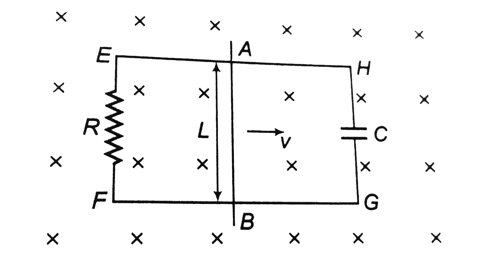
i. Current in loop `AEFBA` is anti clockwise
ii. Current in loop `AEFBA` is clockwise
iii Current through the capacitor is zero
iv Energy stored in the caspacitor is `1/2 CB^2L^2v^2`
Which is the following options in correct?
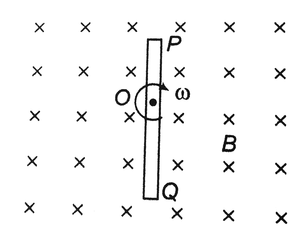
View SolutionA rod is rotating with a constant angular velocity `omega` about point `O` (its centre) in a magnetic field `B` as shown. Which of the folloiwng figure correctly shows the distribution of charge inside the rod?
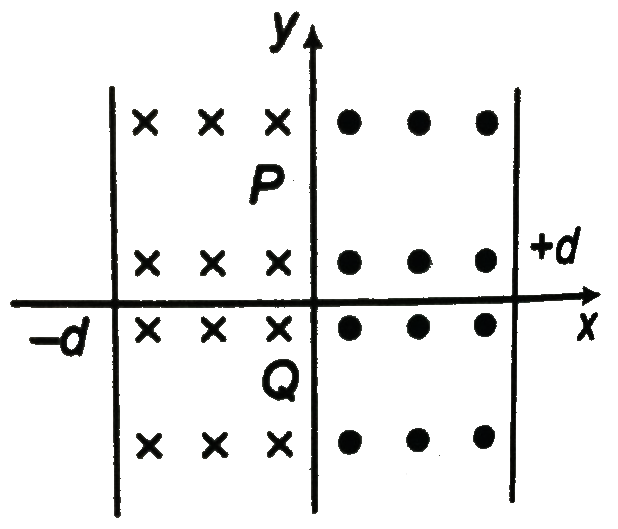
View SolutionA straight conductig rod `PQ` is executing `SHM` in xy-plane from `x=-d` to `x=+d.` Its mean position is `x=0` and its length is along `y`-axis. There exists a uniform magnetic field B from `x=-d` to `x=0` pointing inward normal to the paper andfrom `x=0` to `x=+d` there exists another uniform magnetic field of same magnetic `B` but pointing outward normal to the plane of the paper. At the instant `t=0`, the rod is at `x=0` and moving to the right. The induced emf (epsilon) acorss the rod `PQ` `vs` time (`t`) graph will be
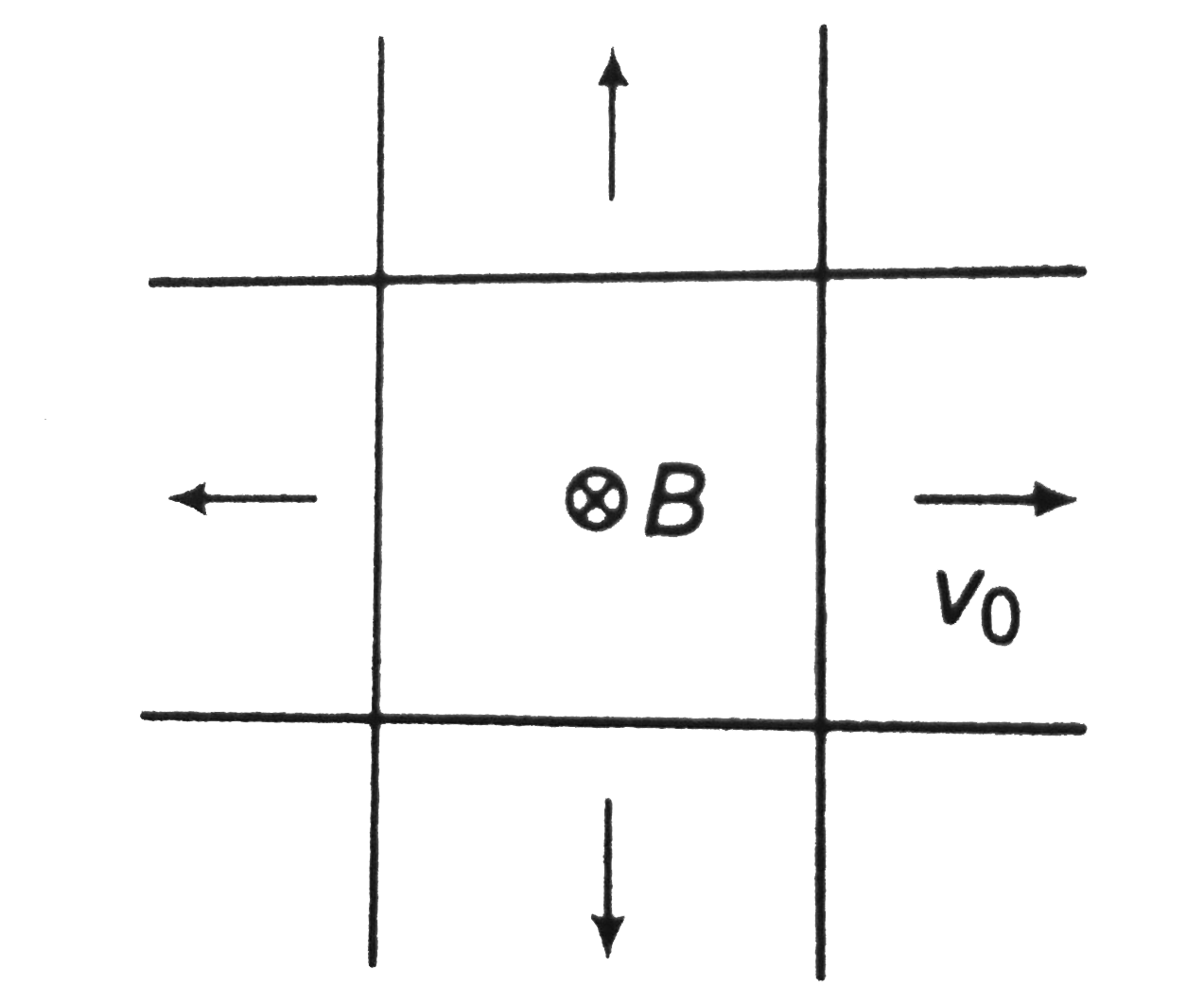
View SolutionTwo parallel long straight conductors lie on a smooth plane surface. Two other parallel conductors rest on them at right angle so as to form a square of side a. A uniform magnetic field B exists at right angle to the plane containing the conductors. Now, conductors starts moving outward witha constant velocity `v_0` at `t=0`. Then, induced current in the loop at any time is `(lamda` is resistance per unit length of the conductors)
View SolutionA conducting square loop is placed in a magnetic field `B` with its plane perpendicular to the field. Now the sides of the loop start shrinking at a constant rate `alpha.` the induced emf in the loop at an instant when its side is a is
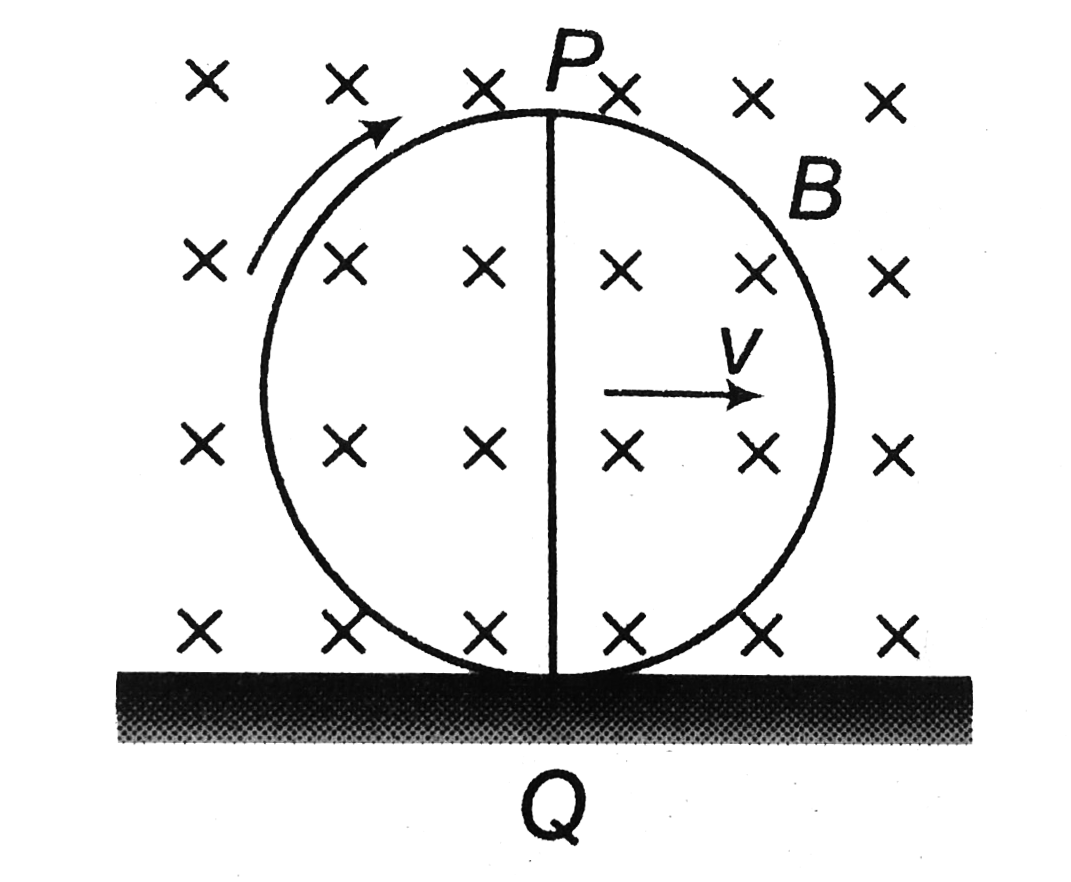
View SolutionA conducting straight wire `PQ` of length `l` is fixed along as diameter of a non conducting ring as shown in the figure. The ring is given a pure rolling motion as shown. Field `B` is horizontal in direction and perpendicular to the plane of ring. The magnitude of induced EMF in the wire PQ at the position shown in figure will be
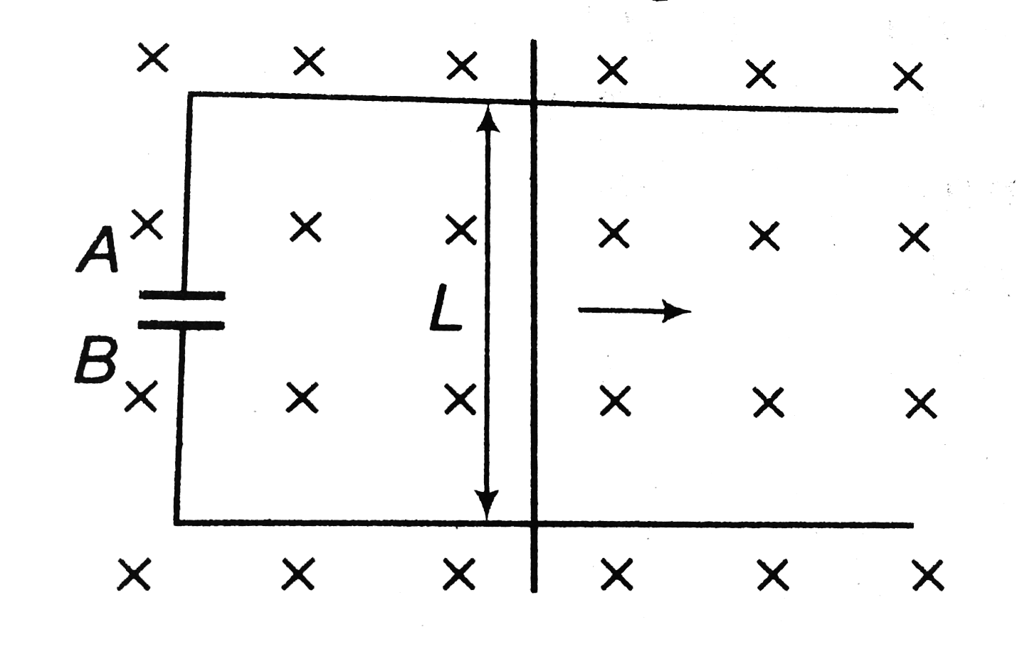
View SolutionA conducting rod of length `L=0.1 m` is moving with a uniform sped `v=0.2m//s` on conducting raisli a magnetic field `B=0.5T` as shown. On one side, the end of the rails is connected to a capacitor of capacitance `C=20muF`. Then, the charge on the capacitor's plates are
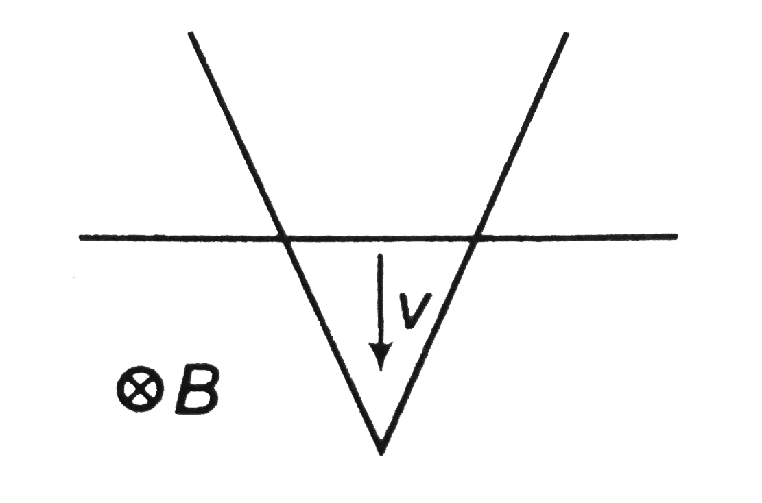
View SolutionA wire is bent in the form of a `V` shape and placed in a horizontal plane.There exists a uniform magnetic field `B` perpendicular to the plane of the wire. A uniform conducting rod starts sliding over the `V` shaped wire with a constant speed v as shown in the figure. If the wire no resistance, the current in rod wil
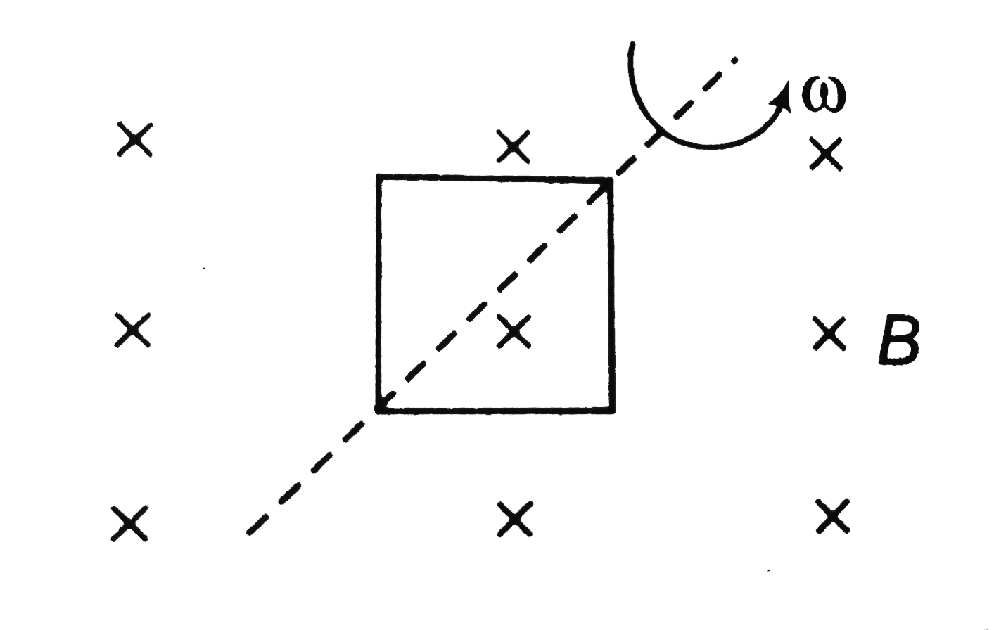
View SolutionA square loop of side `b` is rotated in a constant magnetic field `B` at angular frequency `omega` as shown in the figure. What is the emf induced in it?
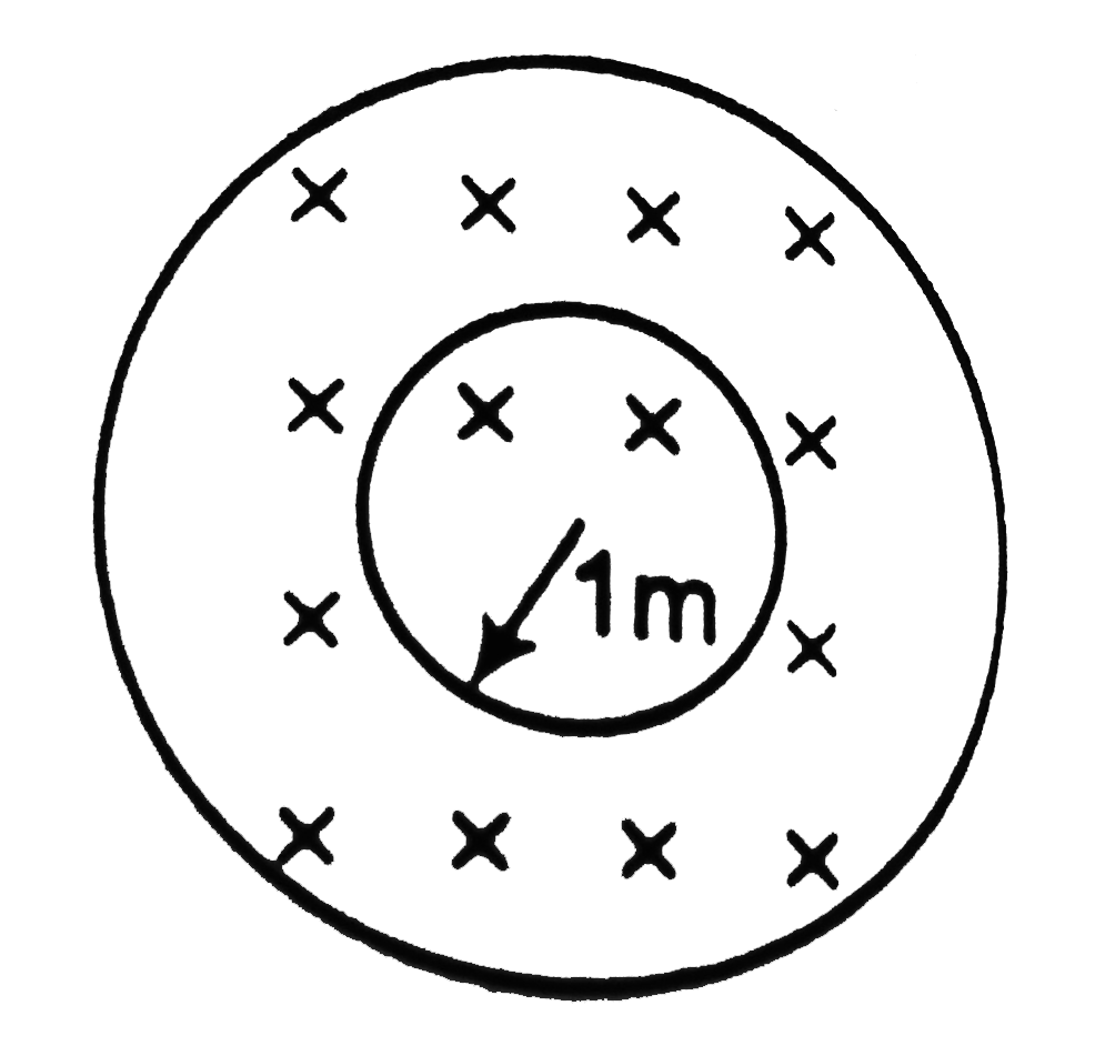
View SolutionA uniform but time varying magnetic field exists in a cylindrical region as shown in the figure. The direction of magnetic field is into the plane of the paper and its magnitude is decreasing at a constant rate of `2xx10^-3T//s`. A particle of charge `1muC` is moved slowly along circle of radius `1m` by an external force as shown in figure. The plane of the circle of radius `1m` by an external force as shown in figure. The plane of he circle lies in the plane of the paper and it is concentric with the cylindrical region. The work done by the external force in moving this charge along the circle will be
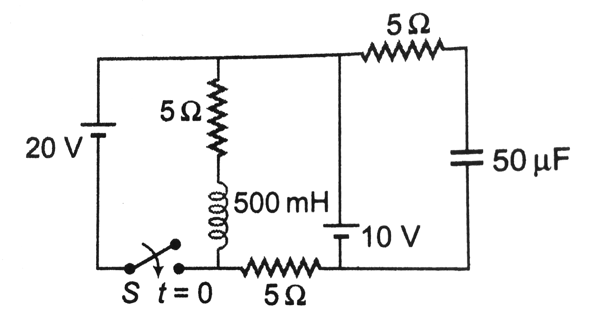
View SolutionSwitch `S` is closed `t=0`, in the circuit shown. The change in flux in the inductor `(L=500mH)` from `t=0` to an instant when it reaches steady state is
View SolutionA coil having an inductance `L` and a resistance `R` is connected to a battery of `emf epsilon`. Find the time elapsed before, the magnetic field energy stored in the circuit reaches half its maximum value.
View SolutionElectric charge `q` is distributed uniformly over a rod of length `l`. The rod is placed parallel to a long wire carrying a current `i`. The separation between the rod and the wire is a. The force needed to move the rod along its length with a uniform velocity `v` is
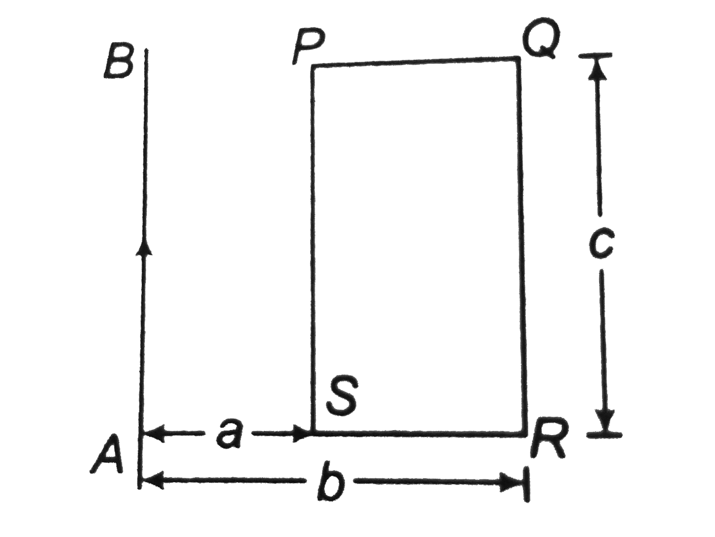
View Solution`AB` is an infinitely long wire placed in the plane of rectangular coil of dimension as shon in the figure. Calculate the mutual inductance of wire `AB` and coil `PQRS`
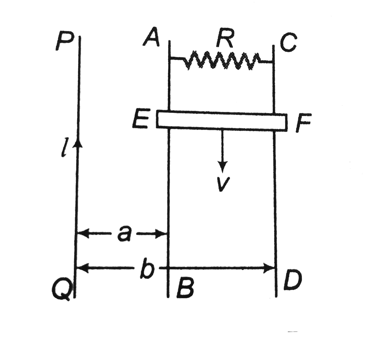
View Solution`PQ` is an infinite current carrying conductor. `AB` and `CD` are smooth conducting rods on which a conductor `EF` moves with constant velocity `v` as shown. The force needed to maintain constant speed of `EF` is
View SolutionFind the flux of point charge q through the square surface ABCD as shown
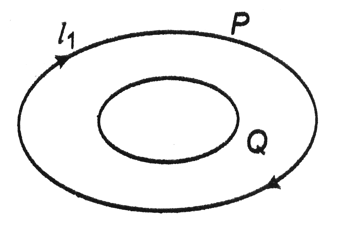
View SolutionTwo circular loops `P` and `Q` are concentric and coplanar as shown in figure. The loop `Q` is smaller than. `P`. If the current `I_1` flowing `i` loop `P` is decreasing with time, then the curren `I_2` in the loop `Q`
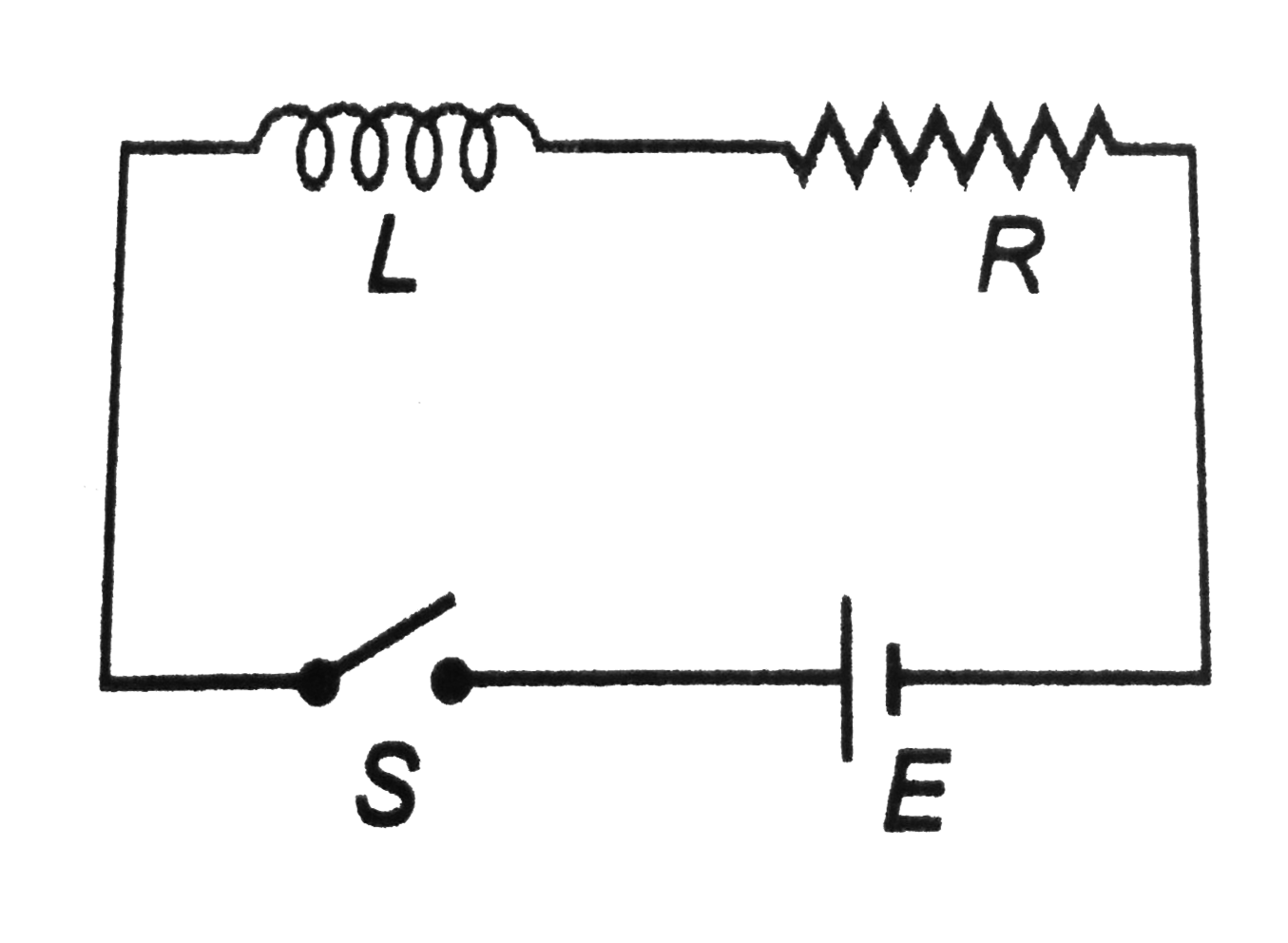
View SolutionIn the circuit shown in figure, the switch `S` is closed at `t=0`. If `V_L` is the voltge induced across the inductor and `i` is the instantaneous current, the correct variation of `V_L` versus is given by
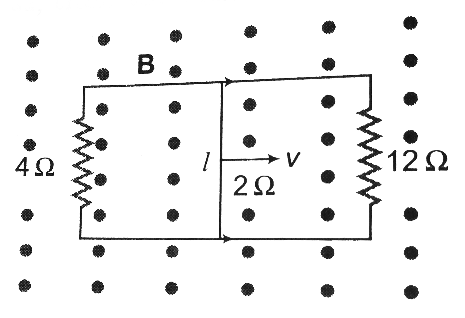
View SolutionIn the figure shown as uniform magnetic field `|B|=0.5T` is perpendicular to the plane of circuit. The sliding rod of length `l=0.25 m` moves uniformly with constant speed `v=4ms^-1`. If the resistance of the sllides is `2Omega`, then the current flowing through the sliding rod is
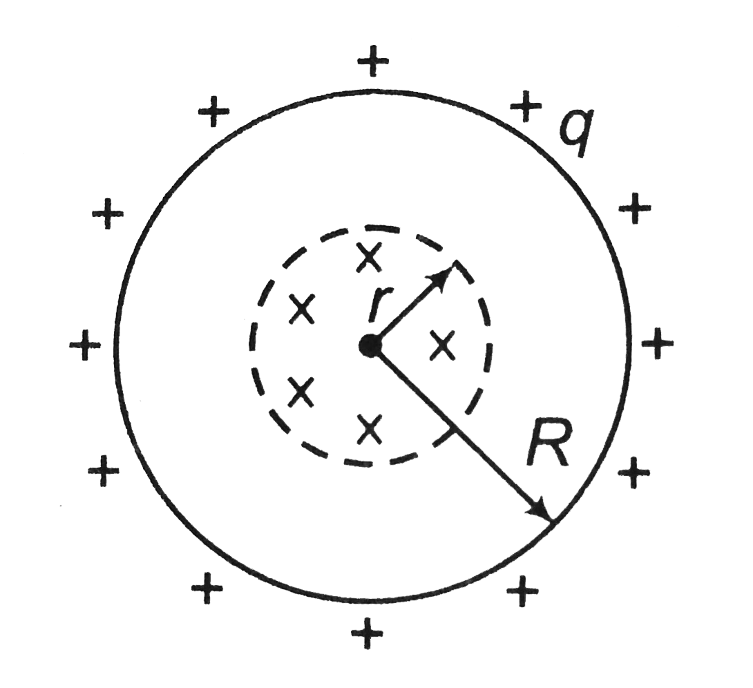
View SolutionThe figure shows a non conducting ring of radius `R` carrying a charge `q`. In a circular region of Radius `r`, a uniform magnetic field `B` perpendicular to the plane of the ring varies at a constant rate `(dB)/(dt)=beta`. The torque on the ring is
View SolutionA conducnting straight wire `PQ` of length `l` is fixed along as diameter of a non conducting ring as shown in the figure. The ring is given a pure rolling motion on as horizontal masgnetic field `B` in horizontal direction perpendicular to the plane of ring. The magnitude of induced emf in the wire PQ at the position shown in figure will be

View SolutionA uniformly wound long solenoid of inductance `L` and resistance `R` is cut into two parts in the ratio `eta:1`, which are then connected in parallel. The combination is then connected to a cell of emf `E`. The time constant of the circuit is
View SolutionWhen a choke coil carrying a steady current is short circuited, the current in it decreases to `beta(lt1)` times its initial value in a time `T`. The time constant of the choke coil is
View SolutionIn the steady state condition the rate of heat produced in a choke coil is `P`. The time constant of the choke coil is `tau`. If now the choke coil is short circuited, then the total head dissipated in the coil is
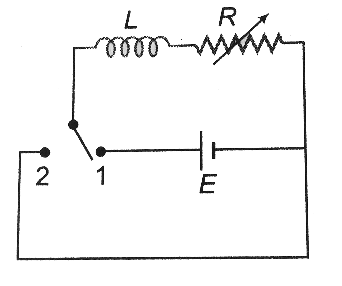
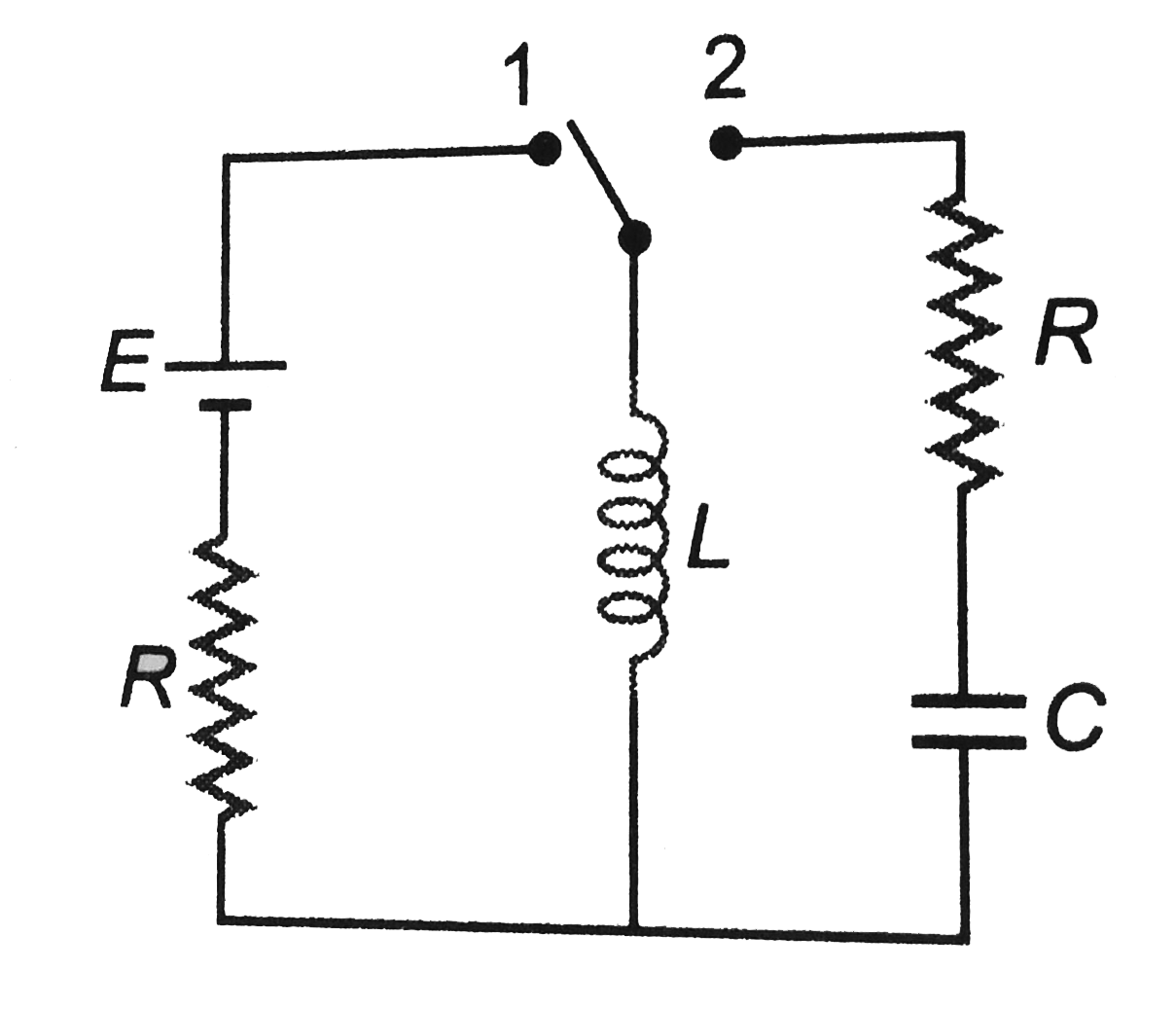
View SolutionIn the circuit shown in the figure initialy the switch in position 1 for a long time, then suddenly at `t=0` the switch is shifted to position 2. It is required that a constant current should flow in the circuit, the value of resistance `R` in the circuit
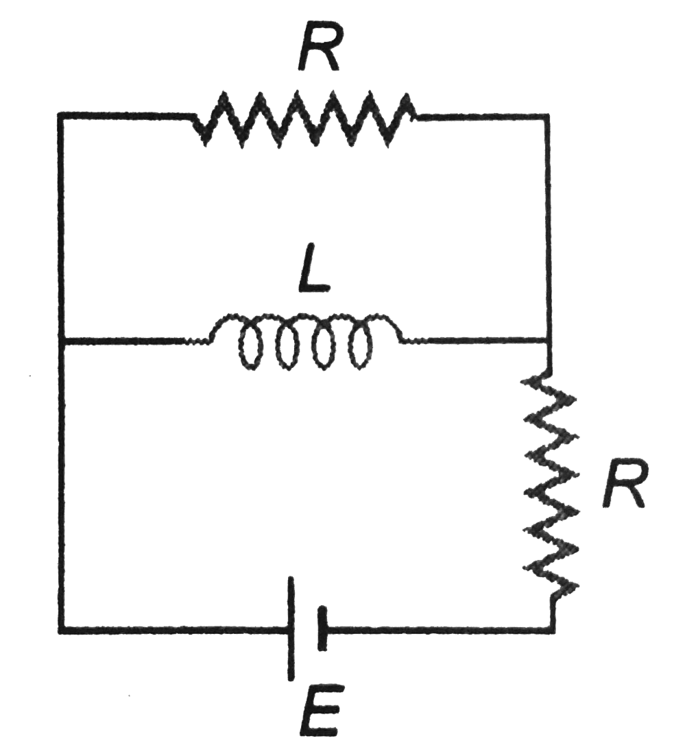
View SolutionThe figure shows an `L-R` circuit the time constant for the circuit is
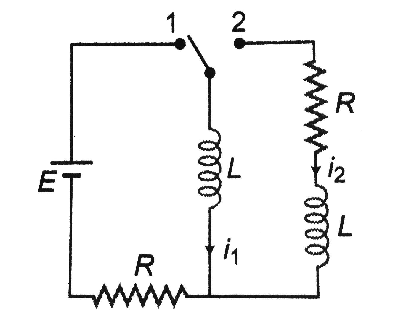
View SolutionIn figure, the switch is in the position 1 for long time, then the switch is shifted to position 2 at `t=0`. At this instant the value of `i_1` and `i_2` are
View SolutionIn a decaying `L-R` circuit, the time after which energy stores in the inductor reduces to one fourth of its initial values is
View SolutionInitially the switch is in positions 1 for as long time then shifted to position 2 at `t=0` as shown in figure. Just after closing the switch, the magnitude of current through the capacitor is
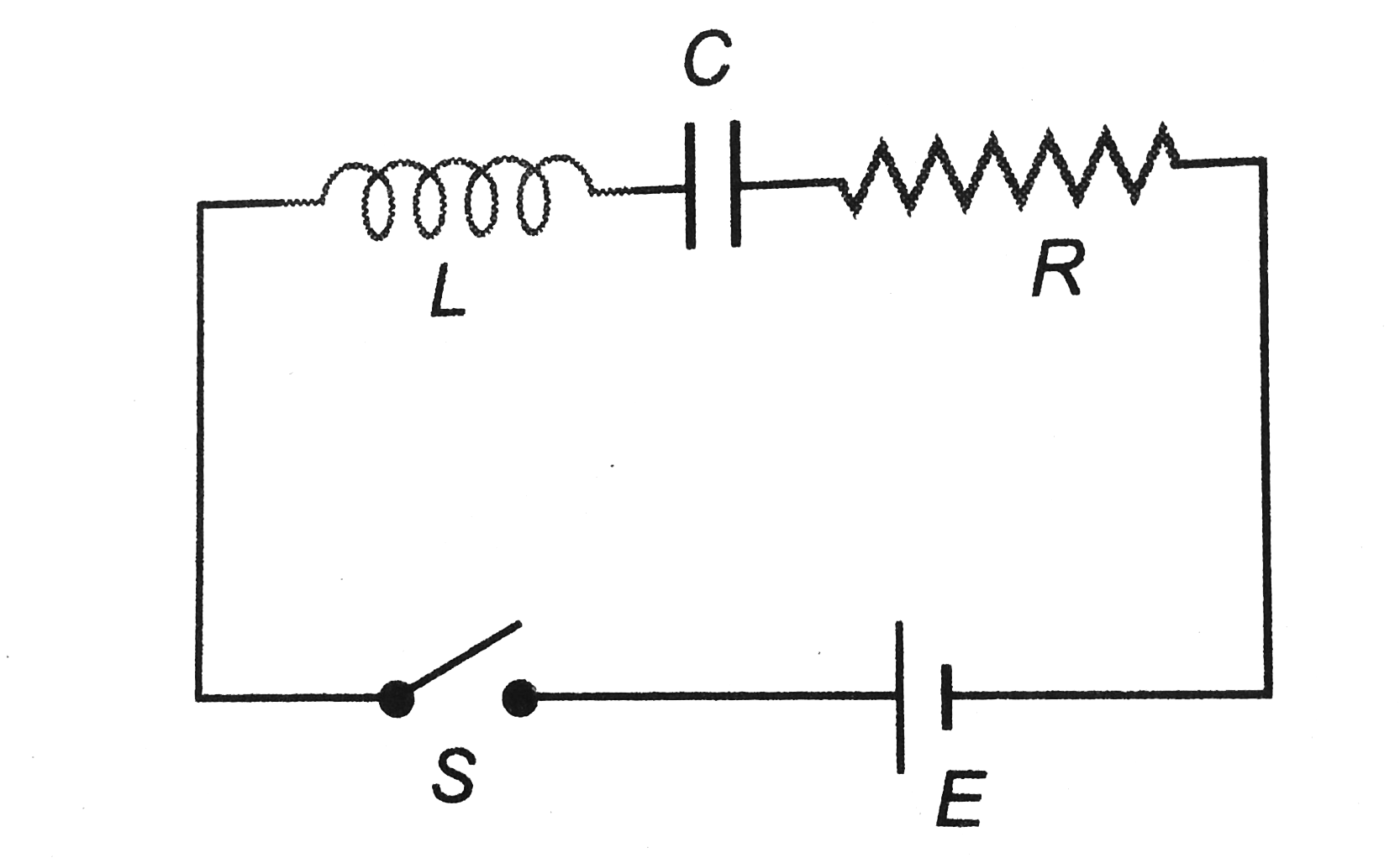
View SolutionWhen the switch `S` is closed at `t=0`, identify the correct statement just after closing the switch as shown in figure
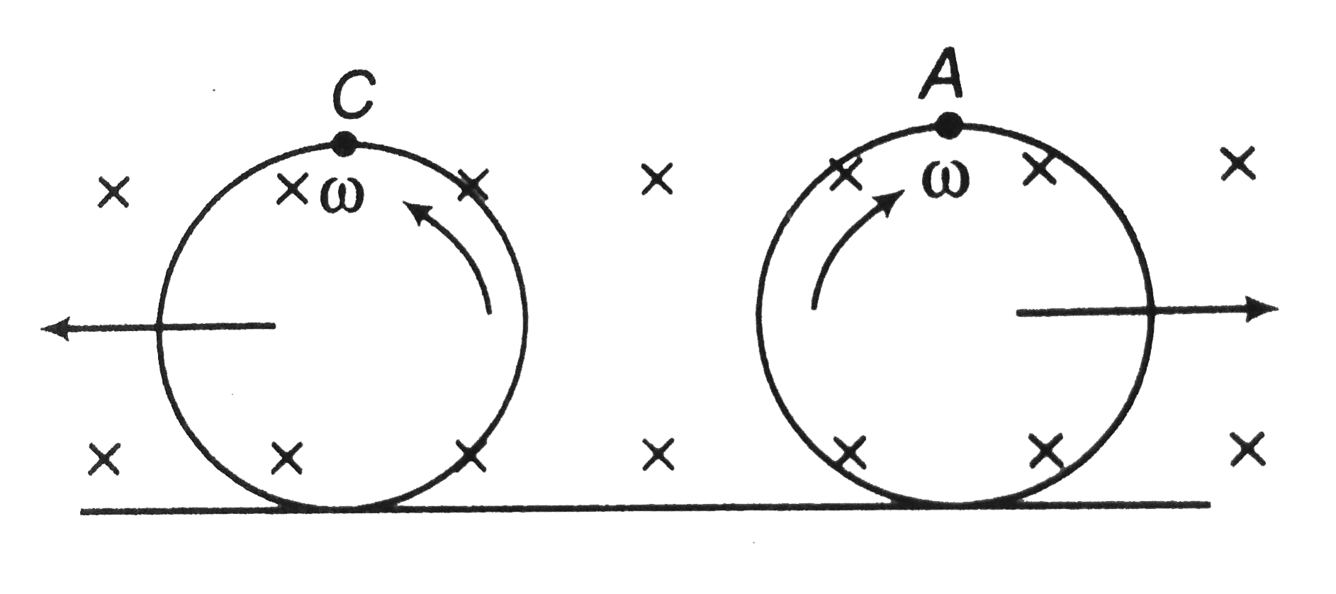
View SolutionTwo metallic rings of radius `R` are rolling on a metalilc rod. A magnetic fied of magnitude B is applied in the region. The magnitude of potential difference between points `A` and `C` on the two rings (as shown) , will be
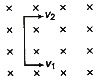
View SolutionIn the figure, magnetic field points into the pane of paper and the conducting rod of length `l` is moving in this field such that the lowest point has a velocity `v_1` and the topmost point has the velocity `v_2(v_2gtv_1)`. The emf induced is given by
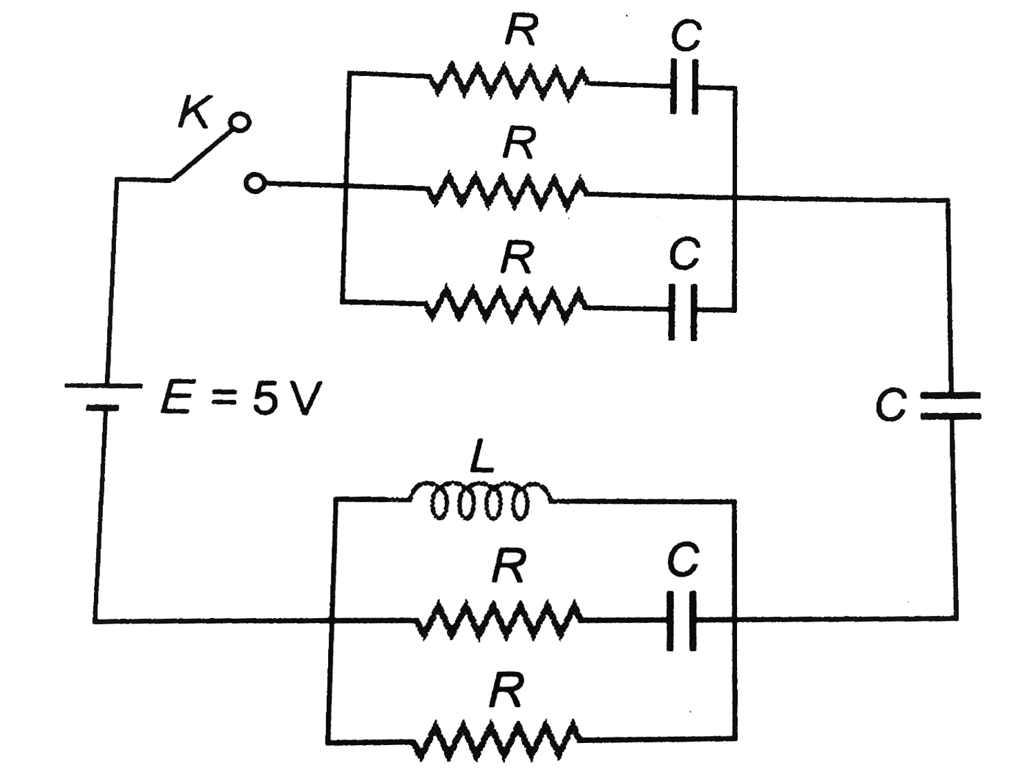
View SolutionFind the current passing through battery immediately after key `(K)` is closed. It is given that initially all the capacitors are uncharged. (Given that `R=6Omega` and `C=4muF)`
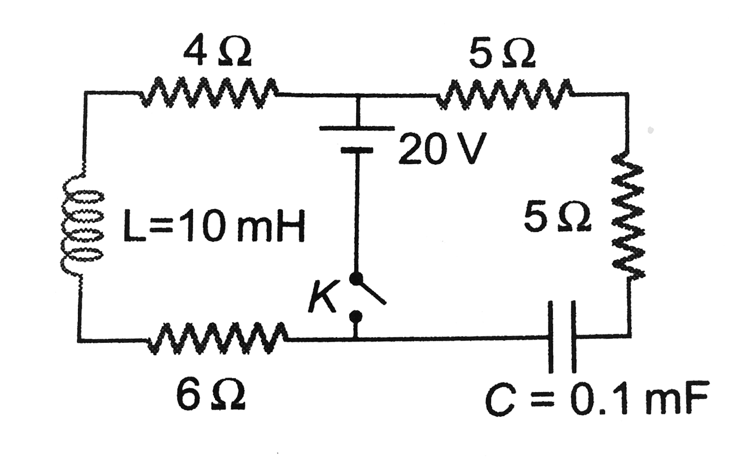
View SolutionIn the circuit shown the key `(K)` is closed at `t=0`, the current through the key at the instant `t=10^-3 ln, 2` is
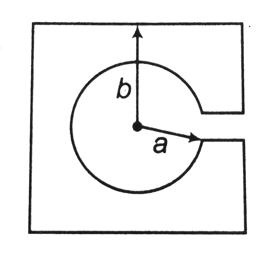
View SolutionA loop shown in the figure is immersed in the varying magnetic field `B=B_0t`, directed into the page. If the total resistance of the loop is `R`, then the direction and magnitude of induced current in the inner circle is
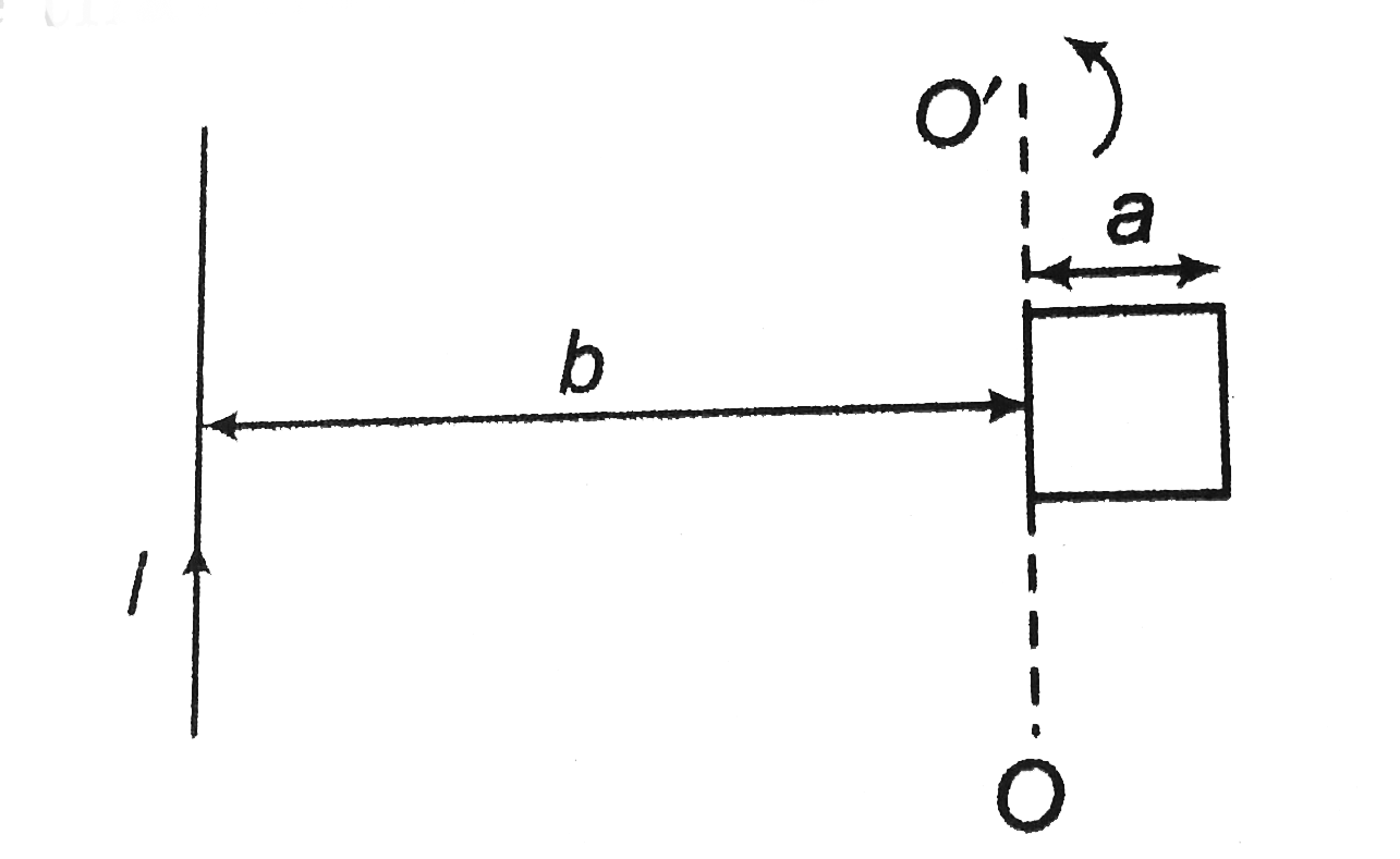
View SolutionA square loop of side as and a straight long wire are placed in the same plane as shown in figure. The loop has a resistance `R` and inductance `L`. The frame is turned through `180^@` about the axis `OO^'`. What is the electric charge that flows through the loop?
View Solution
Level 2 Single Correct questions and complete solutions for chapter ELECTROMAGNETIC INDUCTION of DC PANDEY ENGLISH of Class 12
All Exercises from DC PANDEY Class 12 PHYSICS ELECTROMAGNETIC INDUCTION
- Check point
- Example
- Example Type 1
- Example Type 2
- Example Type 3
- Example Type 4
- Example Type 5
- Example Type 6
- Exercise 27.1
- Exercise 27.2
- Exercise 27.3
- Exercise 27.4
- Exercise 27.5
- Exercise 27.6
- Exercise 27.7
- Level 1 Assertion And Reason
- Level 1 Objective
- Level 1 Subjective
- Level 2 Comprehension Based
- Level 2 More Than One Correct
- Level 2 Single Correct
- Level 2 Subjective
- Match the columns
- Medical entrance special format questions
- Medical entrances gallery
- Miscellaneous Examples
- Objective Questions
- SUBJECTIVE TYPE
- Taking it together