Complete Solutions to Level 2 Subjective of chapter ELECTROMAGNETIC INDUCTION of Class 12 book with complete answers and questions
| Class 12 | PHYSICS |
| Chapter | ELECTROMAGNETIC INDUCTION |
| DC PANDEY | Level 2 Subjective |
| Number Of Questions | 20 |
| Academic Year | 2023-24 |
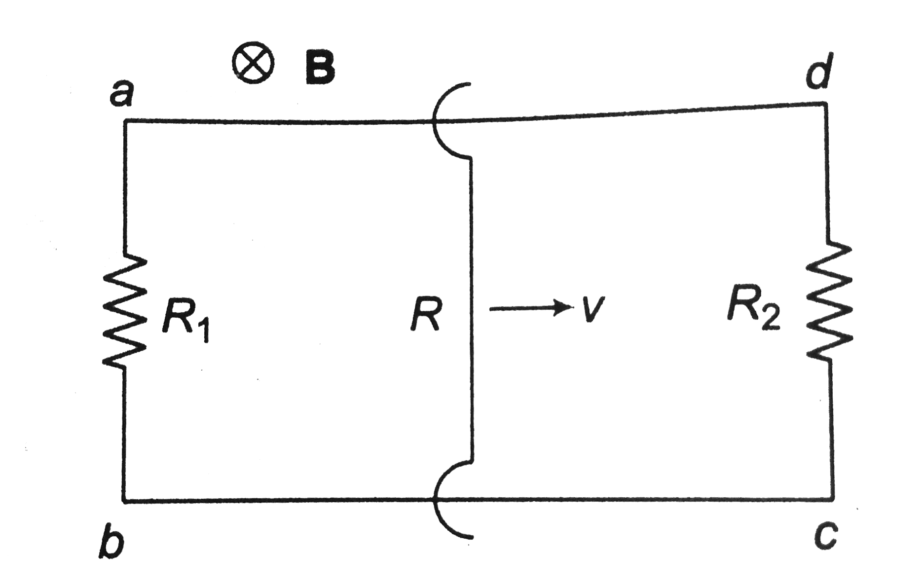
A rectangular loop with a sliding connector of length `l` is located in a uniform magnetic field perpendicular to the loop plane. The magnetic induction is equal to B. The connector has an electric resistance `R`, the sides `ab` and `cd` have resistances `R_1` and `R_2`. Neglecting the self-inductance of the loop, find the current flowing in the connector during its motion with a constant velocity v.
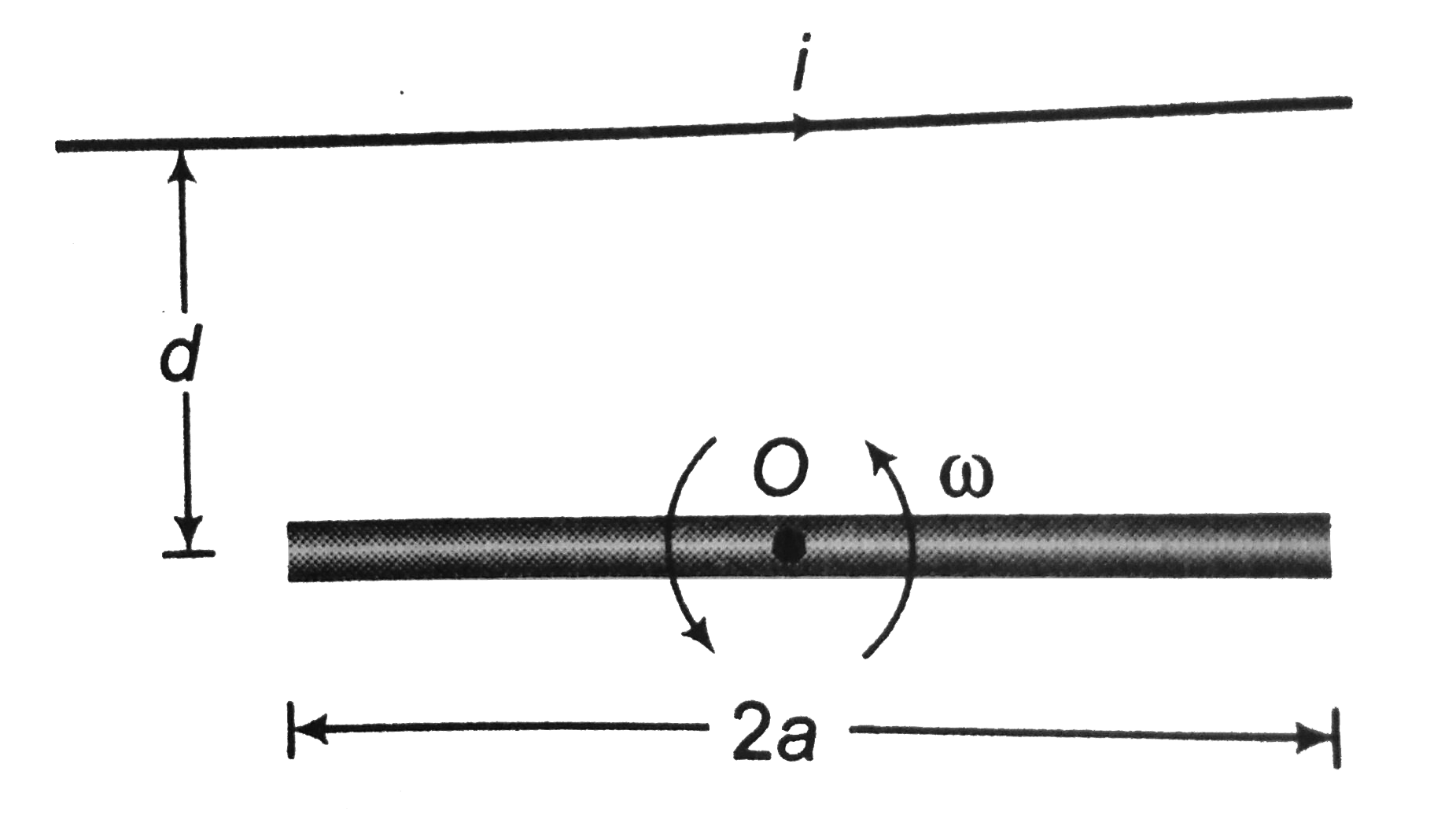
View SolutionA rod of length `2a` is free to rotate in a vertical plane, about a horizontal axis `O` passing through its mid-point. A long straight, horizontal wire is in the same plane and is carrying a constant current i as shown in figure. At initial moment of time, the rod is horizontal and starts to rotate with constant angular velocity `omega`, calculate emf induced in the rod as a function of time.
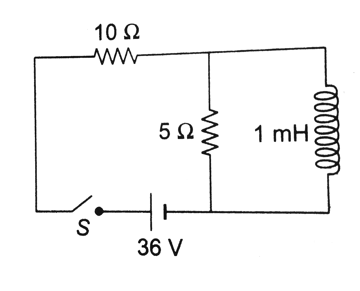
View SolutionIn the circuit arrangement shown in figure, the switch `S` is closed at `t = 0`. Find the current in the inductance as a function of time? Does the current through `10 Omega` resistor vary with time or remains constant.
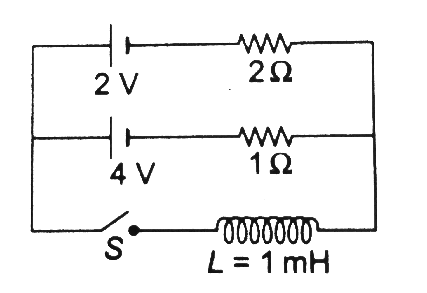
View SolutionIn the circuit shown, switch `S` is closed at time `t = 0`. Find the current through the inductor as a function of time `t`.
View SolutionIn the circuit shown in figure, `E = 120 V, R_1 = 30.0Omega, R_2 = 50.0 Omega` and `L=0.200H`. Switch `S` is closed at `t = 0`. Just after the switch is closed.
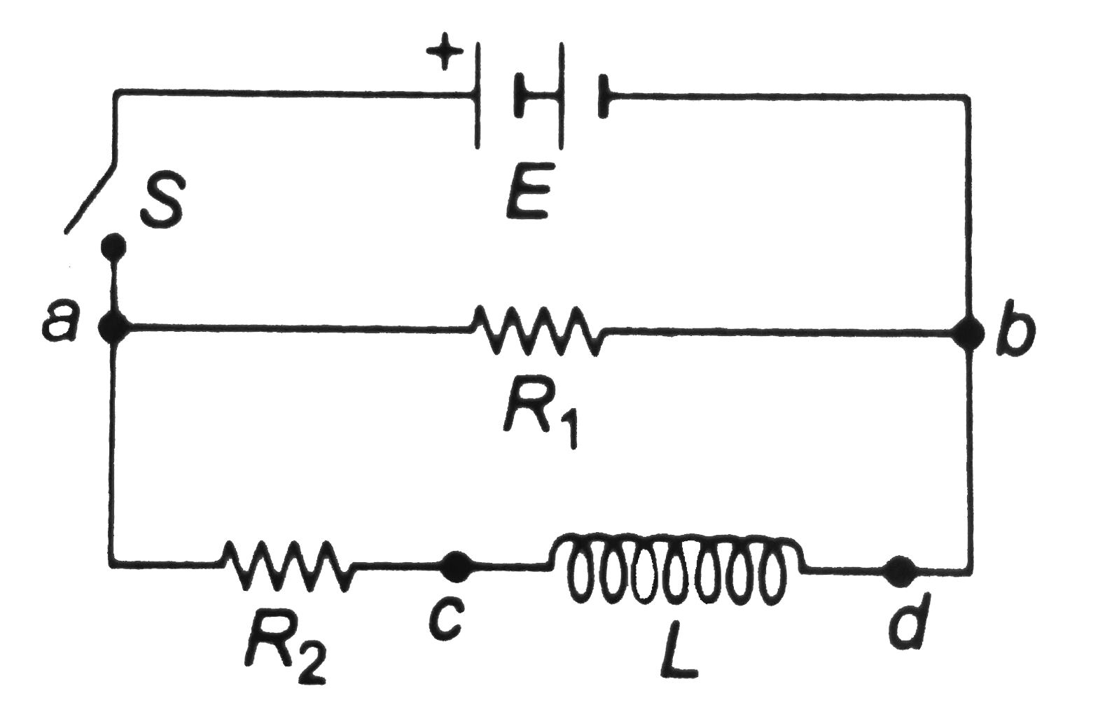
(a) What is the potential difference `V_(ab)` across the inductor `R_1`?
(b) Which point, `a` or `b`, is at higher potential?
(c) What is the potential difference `V_(cd)` across the inductor `L`?
(d) Which point, `c` or `d`, is at a higher potential? The switch is left closed for a long time and then is opened. Just after the switch is opened
(e) What is the potential difference `V_(ab)` across the resistor `R_1`?
(f) Which point a or b, is at a higher potential?
(g) What is the potential difference `V_(cd)` across the inductor `L`?
(h) Which point, `c` or `d`, is at a higher potential?
View SolutionTwo capacitors of capacitances `2C` and `C` are connected in series with an inductor of inductance `L`. Initially, capacitors have charge such that `V_B - V_A = 4V_0` and `V_C- V_D = V_0`. Initial current in the circuit is zero. Find
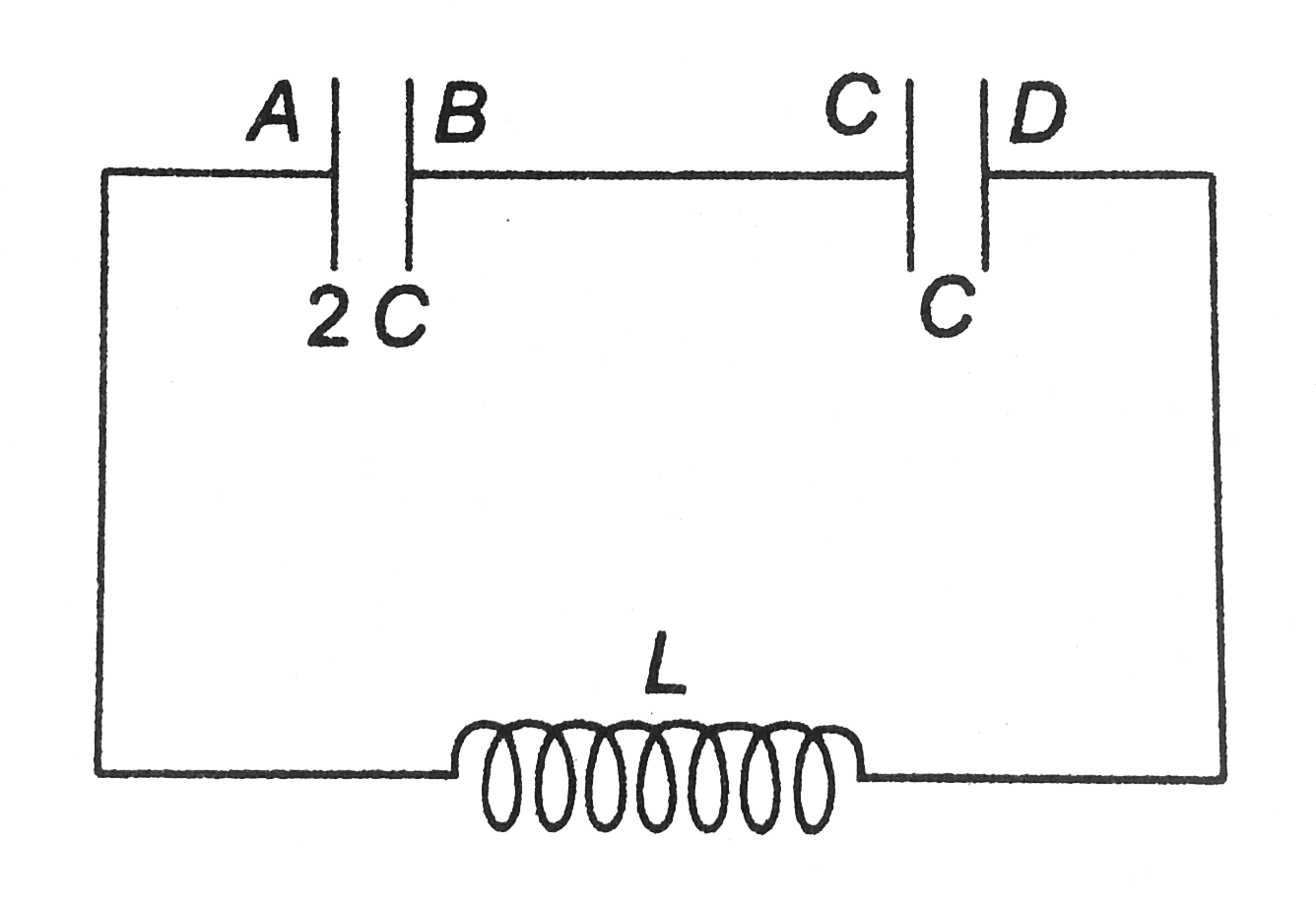
(a) maximum current that will flow in the circuit,
(b) potential difference across each capacitor at that instant,
(c) equation of current flowing towards left in the inductor.
View SolutionA `1.00 mH` inductor and a `1.00muF` capacitor are connected in series. The current in the circuit is described by `i = 20 t`, where t, is in second and `i` is in ampere. The capacitor initially has no charge. Determine
(a) the voltage across the inductor as a function of time,
(b) the voltage across the capacitor as a function of time,
(c) the time when the energy stored in the capacitor first exceeds that in the inductor.
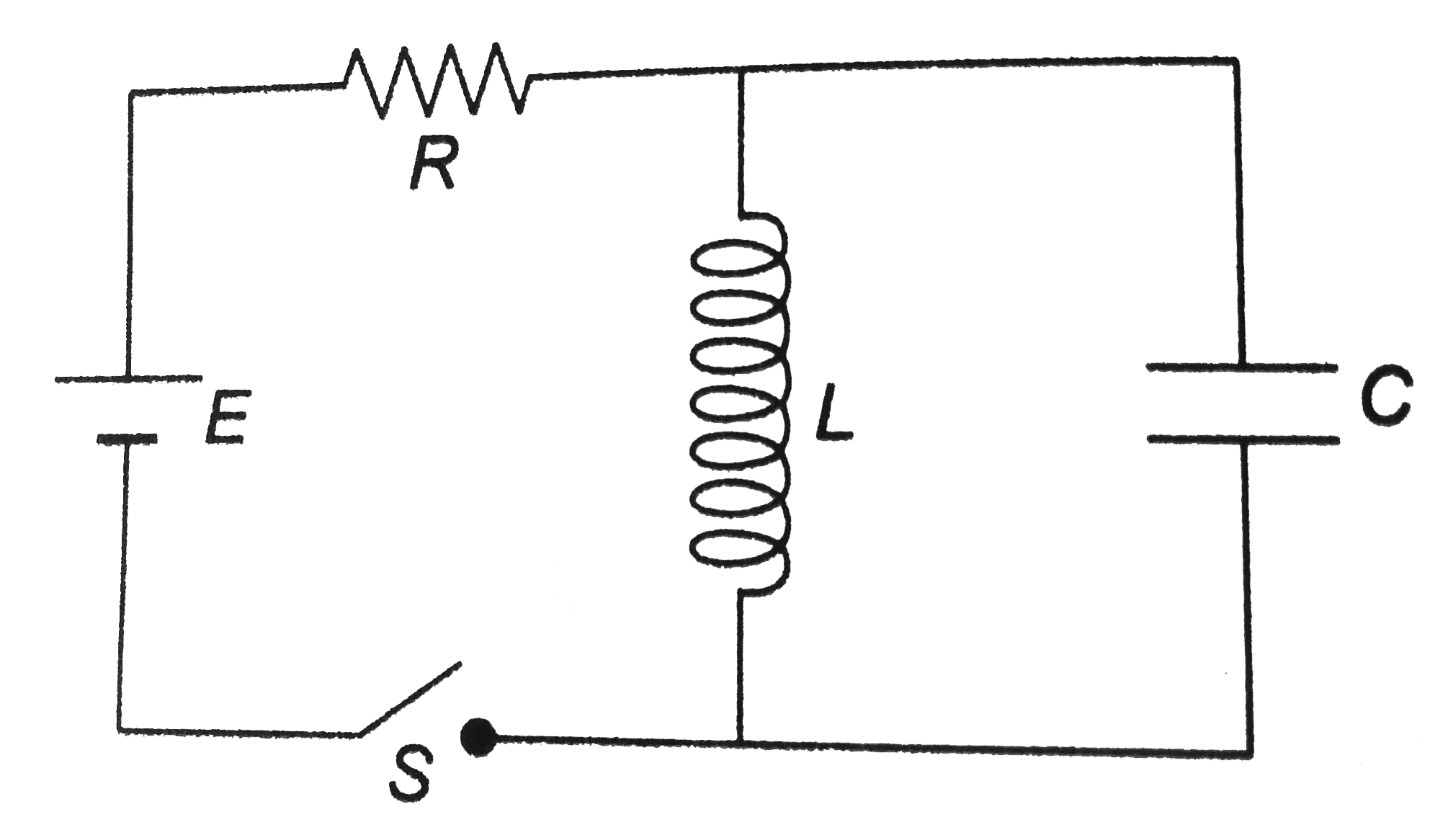
View SolutionIn the circuit shown in the figure, `E = 50.0 V, R = 250 Omega` and `C = 0.500 muF.` The switch `S` is closed for a long time, and no voltage is measured across the capacitor. After the switch is opened, the voltage across the capacitor reaches a maximum value of `150 V`. What is the inductance `L`?
View SolutionThe conducting rod `ab` shown in figure makes contact with metal rails `ca` and `db`. The apparatus is in a uniform magnetic field `0.800 T`, perpendicular to the plane of the figure.
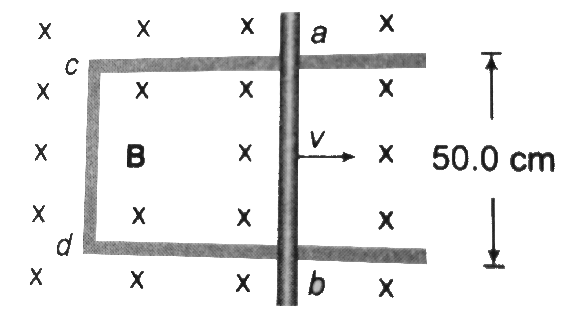
(a) Find the magnitude of the emf induced in the rod when it is moving toward the right with a speed `7.50 m//s`.
(b) In what direction does the current flow in the rod?
(c) If the resistance of the circuit abdc is `1.50 Omega` (assumed to be constant), find the force (magnitude and direction) required to keep the rod moving to the right with a constant speed of `7.50 m//s`. You can ignore friction.
(d) Compare the rate at which mechanical work is done by the force `(Fu)` with the rate at which thermal energy is developed in the circuit `(I^2R)`.
View SolutionA non-conducting ring of mass `m` and radius `R` has a charge `Q` uniformly distributed over its circumference. The ring is placed on a rough horizontal surface such that plane of the ring is parallel to the surface. A vertical magnetic field `B = B_0t^2` tesla is switched on. After 2 a from switching on the magnetic field the ring is just about to rotate about vertical axis through its centre.
(a) Find friction coefficient `mu` between the ring and the surface.
(b) If magnetic field is switched off after `4 s`, then find the angle rotated by the ring before coming to stop after switching off the magnetic field.
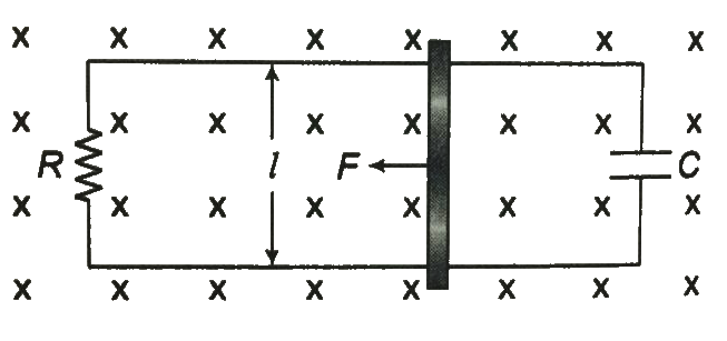
View SolutionTwo parallel long smooth conducting rails separated by a distance `l` are connected by a movable conducting connector of mass `m`. Terminals of the rails are connected by the resistor `R` and the capacitor `C` as shown in figure. A uniform magnetic field `B` perpendicular to the plane of the rail is switched on. The connector is dragged by a constant force `F`. Find the speed of the connector as a function of time if the force `F` is applied at `t = 0`. Also find the terminal velocity of the connector.
View SolutionA circuit containing capacitors `C_1` and `C_2`, shown in the figure is in the steady state with key `K_1` and `K_2` opened. At the instant `t = 0`, `K_1` is opened and `K_2` is closed.
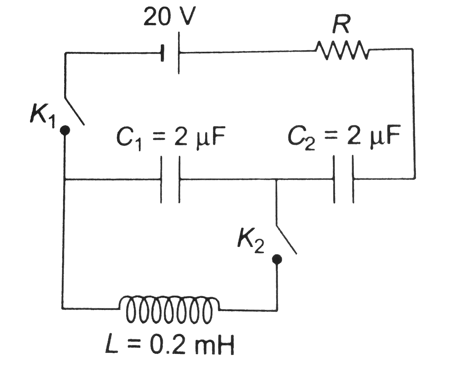
(a) Find the angular frequency of oscillations of `L- C` circuit.
(b) Determine the first instant `t`, when energy in the inductor becomes one third of that in the capacitor.
(c) Calculate the charge on the plates of the capacitor at that instant.
View SolutionInitially, the capacitor is charged to a potential of `5 V` and then connected to position 1 with the shown polarity for `1 s`. After `1s` it is connected across the inductor at position 2
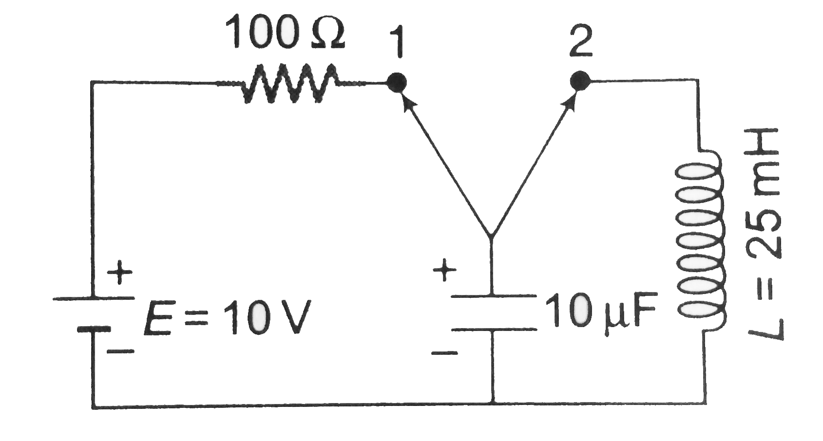
(a) Find the potential across the capacitor after `1 s` of its connection to position 1.
(b) Find the maximum current flowing in the `L- C` circuit when capacitor is connected across the inductor. Also, find the frequency of `LC` oscillations.
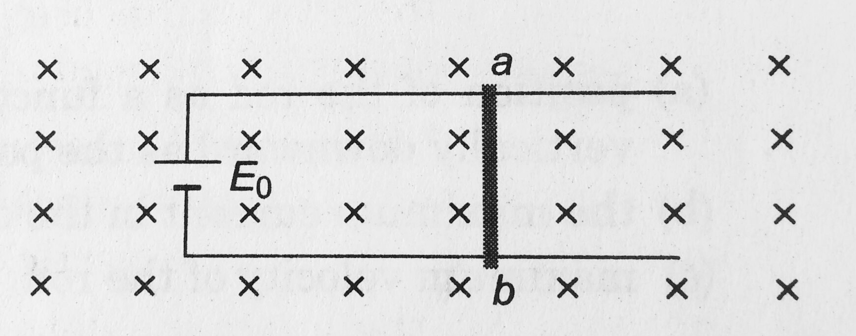
View SolutionA rod of mass `m` and resistance `R` slides on frictionless and resistance less rails at distance `l` apart, that include a source of emf `E_0` (see figure). The rod is initially at rest. Find the expression for the
a. Velocity of the rod v(t).
b. current in the loop i(t).
View SolutionTwo metal bars are fixed vertically and are connected on the top by a capacitor `C`. A sliding conductor of length land mass m slides with its ends in contact with the bars. The arrangement is placed in a uniform horizontal magnetic field directed normal to the plane of the figure. The conductor is released from rest. Find the displacement `x(t)` of the conductor as a function of time t.

View SolutionA conducting light string is wound on the rim of a metal ring of radius `r` and mass `m`. The free end of the string is fixed to the ceiling. A vertical infinite smooth conducting plane is always tangent to the ring as shown in the figure. A uniform magnetic field Bis applied perpendicular to the plane of the ring. The ring is always inside the magnetic field. The plane and the strip are connected by a resistance `R`. When the ring is released, find
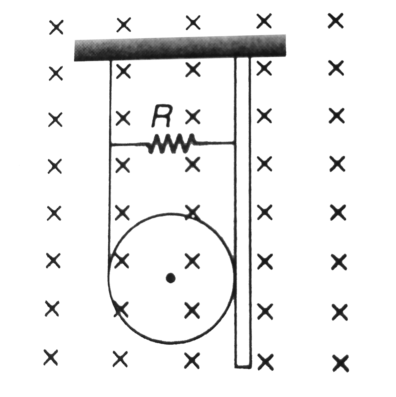
a. the curent in the resistance `R` as as function of time.
b. the terminal velocity of the ring.
View SolutionA conducting frame abcd is kept in a vertical plane. A conducting rod of of mass m and length `l` can slide smoothly on it remaining always horizontal. The resistance of the loop is negligible and inductance is constant having value `L`. The rod is left from rest and allowed to fall under gravity and inductor has no initial current. A magnetic field of constant magnitude Bis present throughout the loop pointing inwards. Determine
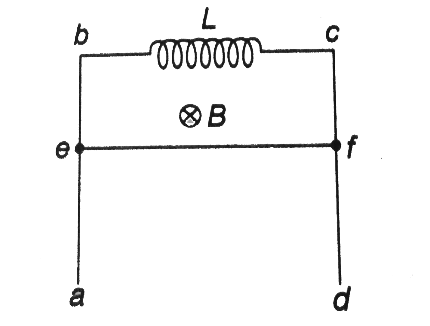
(a) position of the rod as a function of time assuming initial position of the rod to be `x=0` and vertically downward as the positive x-axis.
(b) the maximum current in the circuit.
(c) maximum velocity of the rod
View SolutionA rectangular loop with a sliding conductor of length `l` is located in a uniform magnetic field perpendicular to the plane of loop. The magnetic induction perpendicular to the plane of loop Is equal to `B`. The part ad and be has electric resistance `R_1` and `R_2`, respectively. The conductor starts moving with constant acceleration `a_0`, at time `t = 0`. Neglecting the self-inductance of the loop and resistance of conductor. Find
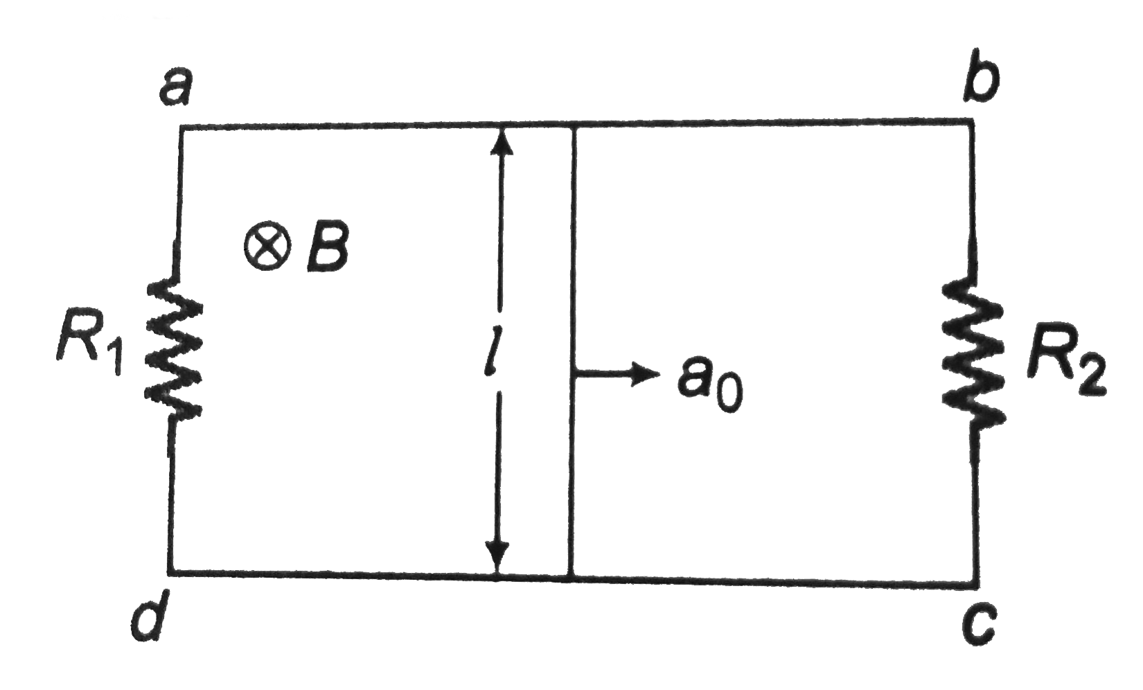
(a) the current through the conductor during its motion.
(b) the polarity of `abcd` terminal.
(c) external force required to move the conductor with the given acceleration.
View SolutionA conducting circular loop of radius a and resistance per unit length R is moving with a constant velocity `v_0` , parallel to an infinite conducting wire carrying current `i_0`. A conducting rod of length `2a` is approaching the centre of the loop with a constant velocity `v_0/2` along the direction 2 of the current. At the instant `t = 0`, the rod comes in contact with the loop at `A` and starts sliding on the loop with the constant velocity. Neglecting the resistance of the rod and the self-inductance of the circuit, find the following when the rod slides on the loop.
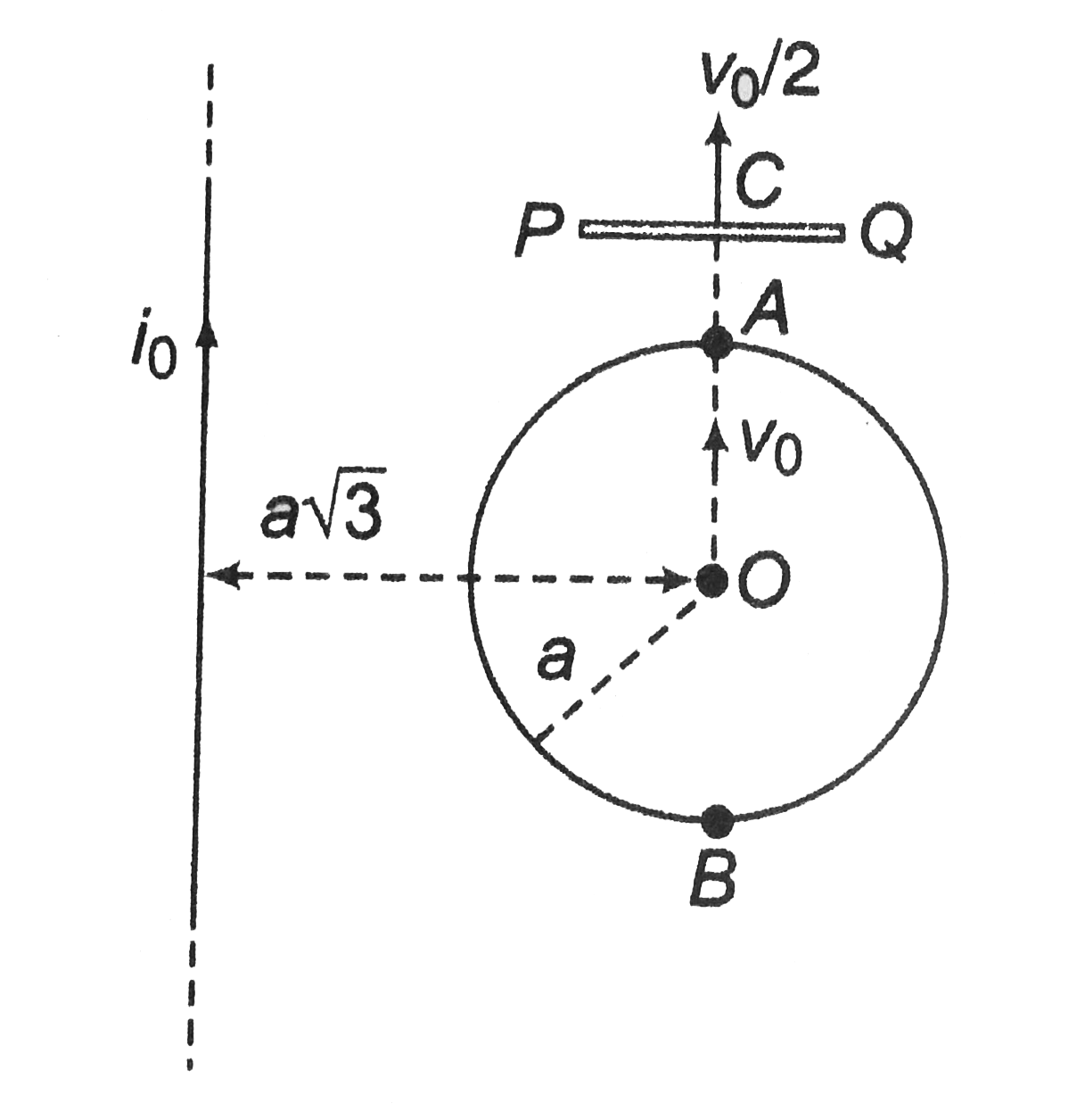
(a) The current through the rod when it is at a distance of `(a/2)` from the point `A` of the loop.
(b) Force required to maintain the velocity of the rod at that instant.
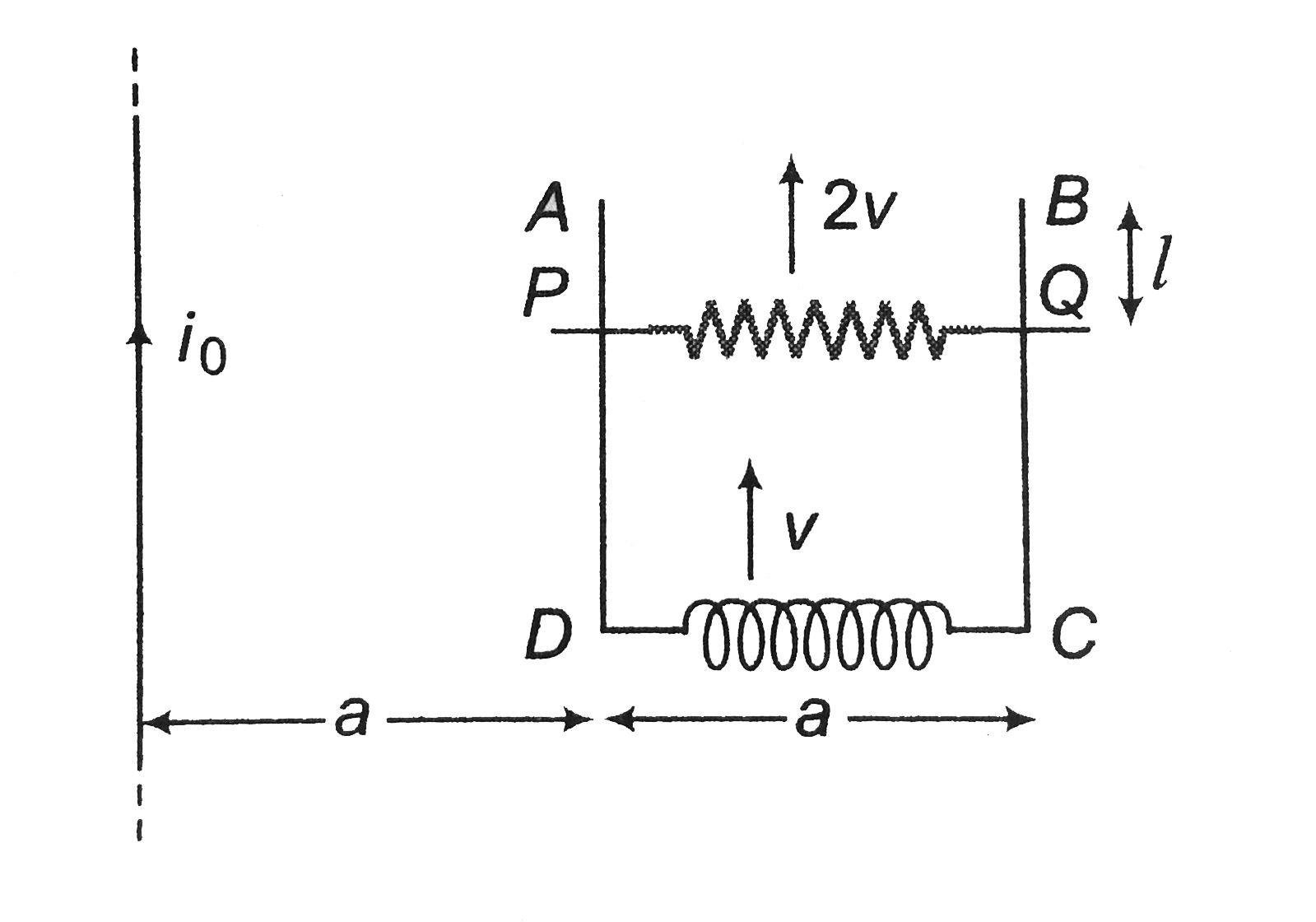
View SolutionU-frame `ABCD` and a sliding rod `PQ` of resistance `R`, start moving with velocities v and `2v` respectively, parallel to a long wire carrying current `i_0`. When the distance `AP =1` at `t = 0`, determine the current through the inductor of inductance `L` just before connecting rod `PQ` loses contact with the U-frame.
View Solution
Level 2 Subjective questions and complete solutions for chapter ELECTROMAGNETIC INDUCTION of DC PANDEY ENGLISH of Class 12
All Exercises from DC PANDEY Class 12 PHYSICS ELECTROMAGNETIC INDUCTION
- Check point
- Example
- Example Type 1
- Example Type 2
- Example Type 3
- Example Type 4
- Example Type 5
- Example Type 6
- Exercise 27.1
- Exercise 27.2
- Exercise 27.3
- Exercise 27.4
- Exercise 27.5
- Exercise 27.6
- Exercise 27.7
- Level 1 Assertion And Reason
- Level 1 Objective
- Level 1 Subjective
- Level 2 Comprehension Based
- Level 2 More Than One Correct
- Level 2 Single Correct
- Level 2 Subjective
- Match the columns
- Medical entrance special format questions
- Medical entrances gallery
- Miscellaneous Examples
- Objective Questions
- SUBJECTIVE TYPE
- Taking it together