Complete Solutions to Level - 1 Objective of chapter ALTERNATING CURRENT of Class 12 book with complete answers and questions
| Class 12 | PHYSICS |
| Chapter | ALTERNATING CURRENT |
| DC PANDEY | Level - 1 Objective |
| Number Of Questions | 30 |
| Academic Year | 2023-24 |
The term `cosphi` in an `AC` circuit is called
View SolutionA `DC` ammeter cannot measure alternating current because
View SolutionAs the frequency of an alternating current increases, the impedance of the circuit
View SolutionPhasor diagram of a series `AC` circuit is shown in figureure. Then,
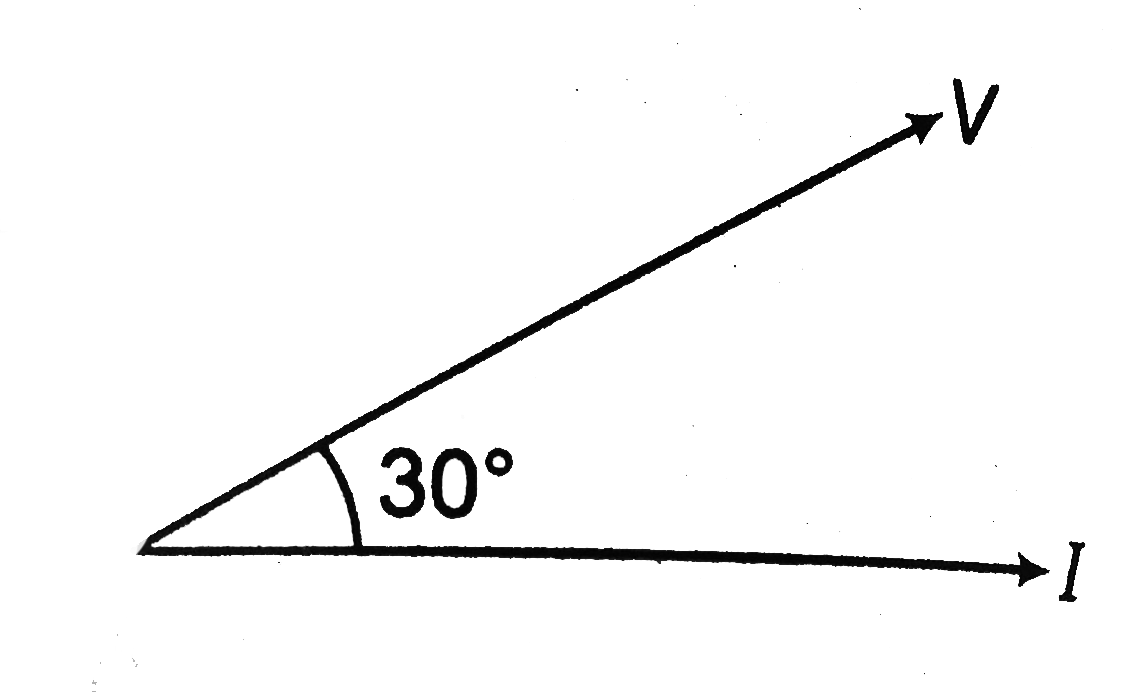
View SolutionThe rms value of an alternating current
View SolutionIn an `AC` circuit, the applied potential difference and the current flowing are given by
`V=20sin100t` volt ,`I=5sin(100t-pi/2)` amp
The power consumption is equal to
View SolutionThe impedasnce of sereis `L-C-R` circuit in an `AC` circuit is
View SolutionIf `V_0` and `I_0` are the peak current and voltge across the resistor in a series `L-C-R` circuit, then the power dissipated in the circuit is `(power factor =costheta)`
View SolutionA generator produces a time varying voltage given by `V=240 sin 120 t,` where `t` is in second. The rms voltage and frequency are
View SolutionAn `L-C-R` series circuit has a maximum current of `5A`. If `L=0.5H` and `C=8muF`, then the angular frequency of `AC` voltage is
View SolutionThe current and voltage functions in an `AC` circuit are
`i=100 sin 100 tmA, V=100sin(100t+pi/3)V`
The power disspitated in the circuit is
View SolutionA capacitor becomes a perfect insulator when the current is
View SolutionFor an alternating voltave `V=10 cos 100 pit` volt, the instantenous voltage at `t=1/600`s is
View SolutionIn a purely resistive `AC` circuit,
View SolutionIdentify the graph which correctly reperesents the variation of capacitive reactance `X_C` with frequency
View SolutionIn an `AC` circuit, the impedance is `sqrt3` times the reactance, then the phase angle is
View SolutionVoltage applied to an `AC` circuit and current flowing in it is given by
`V=200sqrt2sin(omegat+pi/4)` and `i=-sqrt2cos(omegat+pi/4)`
Then, power consumed in the circuited will be
View SolutionA current of `4A` flows in a coil when connected to a `12V DC` source. If the same coil is connected to a `12V, 50 rad//s AC` source, a current of `2.4A` flows in the circuit. Determine the inductance of the coil. Also, find the power developed in the circuit if a`2500muF` capacitor is connected in series with the coil.
View SolutionIn the circuit shown in figureure, the reading of the `AC` ammeter is
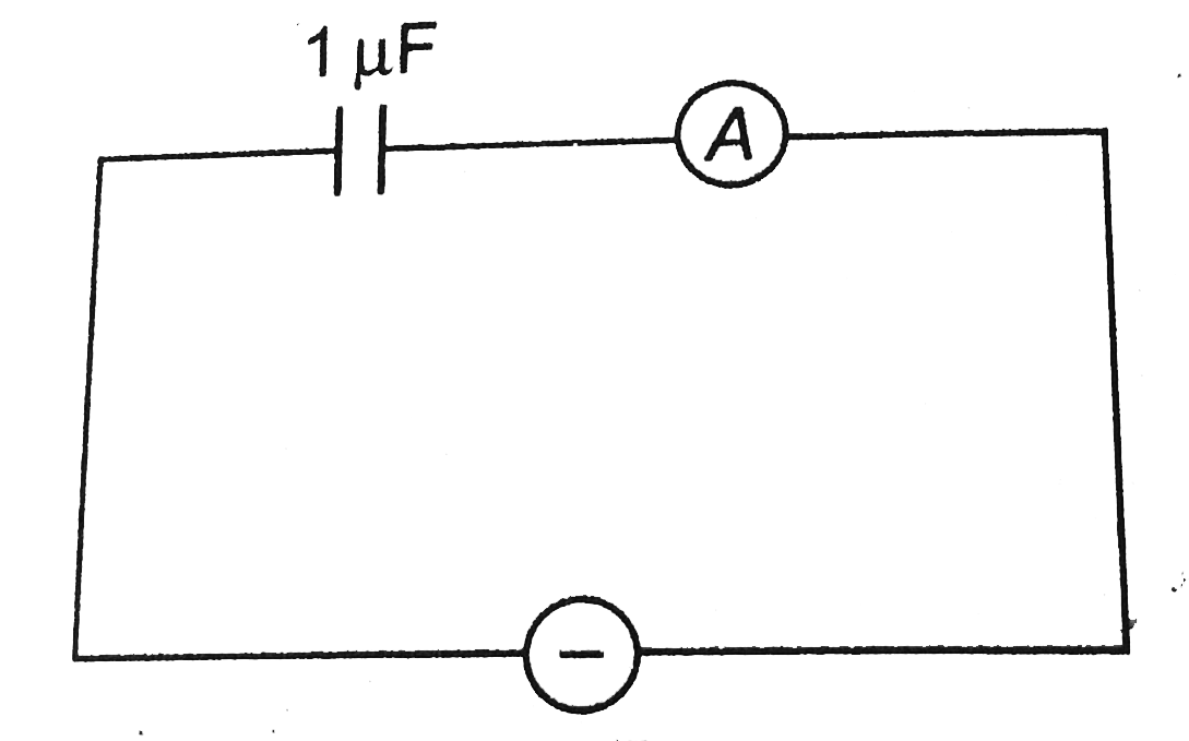 .
.
View SolutionAn `AC` voltage is applied acrss a series combination of `L` and `R`. If the voltage drop across the resistor and inductor are `20 V` and `15 V` respectiely, then applied peak voltage is
View SolutionFor wattless power is an `AC` circuit, the phase angle between the current and voltagge is
View SolutionThe correct variation of resistance `R` with frequency `f` is given by
View SolutionIf `L` and `R` be the inductance and resistance of the choke coil, then indentify the correct statement
View SolutionWhen an `AC` signal of frequency `1 kHz` is applied across a coil of resistance `100 Omega`, then the applied voltage leads the current by `45^@`. The inductance of the coil is
View SolutionThe frequency of an alternating current is `50 Hz`. The minimum time taken by it is reaching from zero to peak value is
View SolutionThe current and voltage functions in an `AC` circuit are
`i=100 sin 100 tmA, V=100sin(100t+pi/3)V`
The power disspitated in the circuit is
View SolutionIn the `AC` network shown in figureure the rms current flowing through the inductor and capacitor are `0.6 A` and `0.8A`, respectively. Then the current coming out of the source is
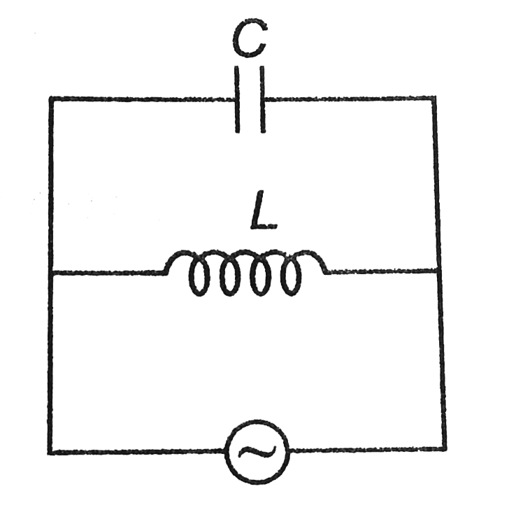 .
.
View SolutionThe figure represents the voltage applied across a pure inductor. The diagram which correctly represents the variation of curent `i` with time `t` is given by
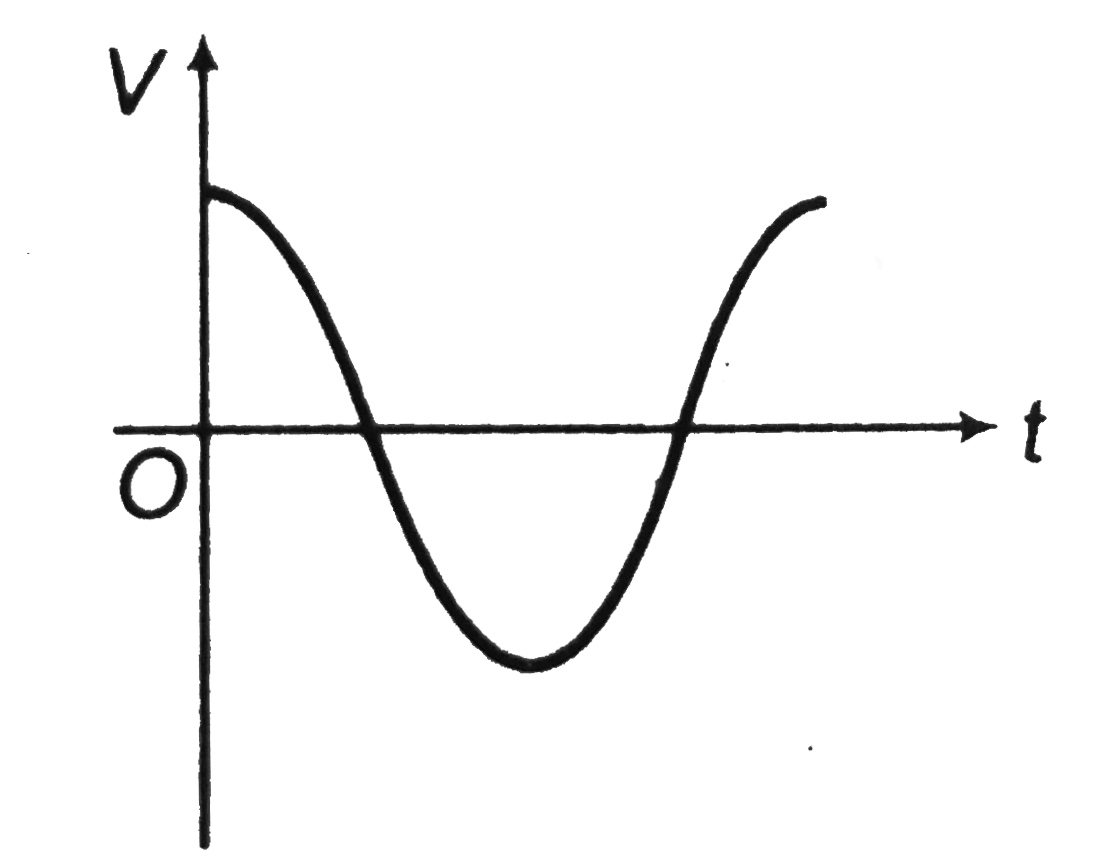 .
.
View SolutionA steady current of magnitude `I` and an `AC` current of peak value `I` are allowed to pass through identical resistors for the same time. The ratio of heat produced in the two resistors will be
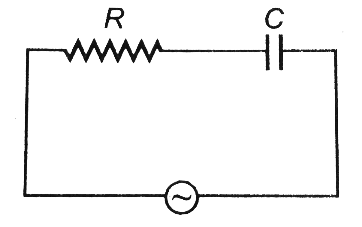
View SolutionA `50 Hz AC` source of `20 V` is connected across `R ` and `C` as shown in figure.
The voltage across `R` is `12 V`. The voltage across `C` is
View Solution
Level - 1 Objective questions and complete solutions for chapter ALTERNATING CURRENT of DC PANDEY ENGLISH of Class 12