Complete Solutions to LEVEL - III (C.W) of chapter ALTERNATING CURRENT of Class 12 book with complete answers and questions
| Class 12 | PHYSICS |
| Chapter | ALTERNATING CURRENT |
| NARAYANA | LEVEL - III (C.W) |
| Number Of Questions | 24 |
| Academic Year | 2023-24 |
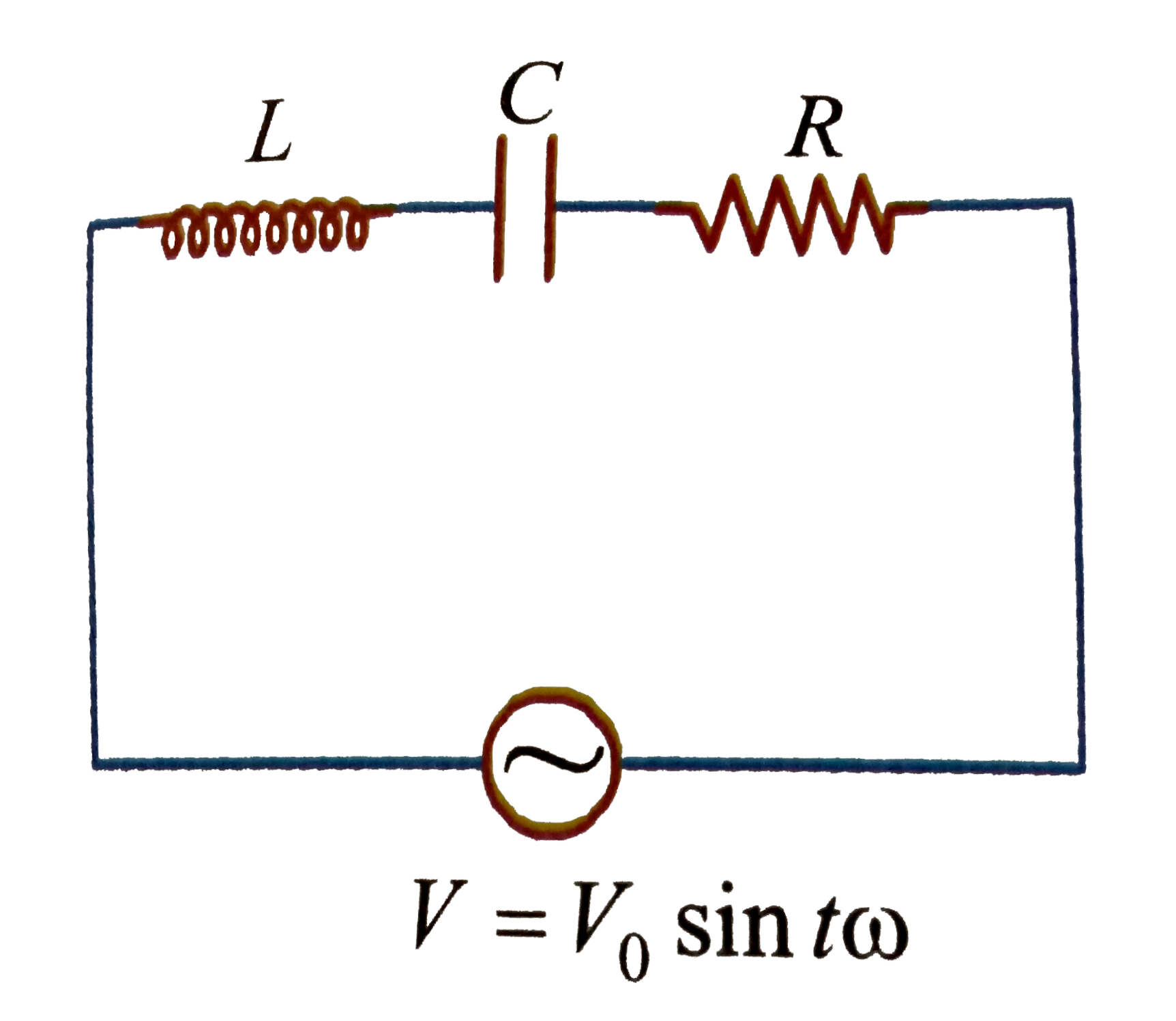
An AC voltage source of variable angular frequency `(omega)` and fixed amplitude `V_(0)` is connected in series with a capacitance C and an electric bulb of resistance R (inductance zero). When `(omega)` is increased
View SolutionIn an `A.C` circuit the instantaneous values of current and voltage are `I = 120 sin omega t` ampare and `E = 300 sin (omega t + pi//3)` volt respectively. What will be the inductive reactance of series `LCR` circuit if the resistance and capacitve reactrance are 2 ohm and 1 ohm respectively?
View SolutionA pure resistive circuit element `'x'` when connected to an `A.C` supply of peak voltage `100 V` gives a peak current of `4 A` which is in phase with the voltage. A second circuit element `'y'` when connected to the same `AC` supply also gives the same value of peak current but the current lags behind by `90^(@)`. If the series combination to of `'x'` and `'y'` is connected to the same supply. `R.M.S` value of current is
View SolutionAn ideal inductor takes a current of `10 A` when connected to a `125 V, 50 Hz AC` supply, A pure resistor across the same source takes `12.5 A`. If the two are connected in series across a `100 sqrt(2) V, 40 Hz` supply, the current through the circuit will be
View SolutionA circuit contanining resistance `R_(1)`, Inductance `L_(1)` and capacitance `C_(1)` connected in series resonates at the same frequency`'n'` as a second combination of `R_(2), L_(2)` and `C_(2)` . If the two are connected in series. Then the circuit will resonates at
View SolutionAn `AC` source of variable frequency is applied across a series `L-C-R` circuit. At a requency double the resonace frequency. The impedance is `sqrt(10)` times the minimum impedance. . The inductive reactance is
View SolutionA `750 Hz, 20 V` source is connected to as resistance of `100 Omega` an inductance of `0.1803 H` and a capacitance of `10 muF` all in sereis.Calculate the time in which the resistance (thermalcapacity `2J//.^(@)C`) wil get heated by `10^(@)C`.
View SolutionAn ac source of angular frequency `omega` is fed across a resistor R and a capacitor C in series. The current registered is I. If now the frequency of source is changed to `omega//3` (but maintaining the same voltage), the current in the circuit is found to be halved. Calculate the ratio of the reactance to resistance at the original frequency `omega`.
View SolutionAn `LCR` circuit has `L = 10 mL, R = 3 Omega`, and `C = 1 mu F` connected in series to a source of `15 cos omega t` volt. The current amplitude at a frequency that is 10% lower then the resonant frequency is
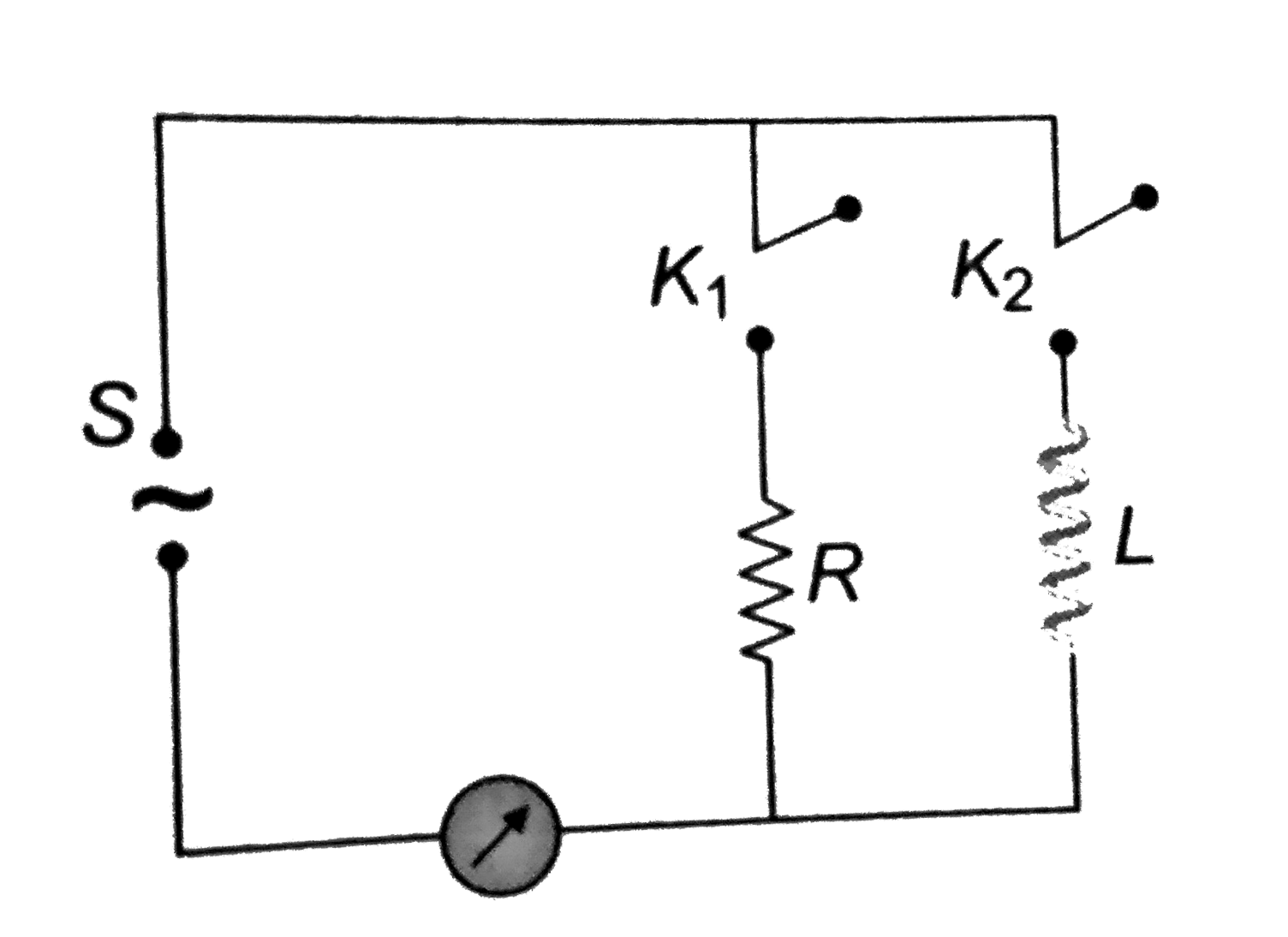
View SolutionIn the circuit shown, `R` is a pure resistor, `L` is an inductor of negligible resistance (as compared to `R`) and `S` is a`100V,50 Hz AC` source of negligible resistance. With eigther key `k_(1)` alone or `k_(2)` alone closed, the current is `I_(0)`. if the source is changed to `100 V, 100 Hz`, the current with `k_(1)` alone closed and with `k_(2)` alone closed will be respectively
View SolutionA capacitor has a resistance of `1200 M Omega` and capacitance of `22 mu F`. When connected to an a.c. supply of frequency 80 hertz, then the alternating voltage supply requried to drive a current of 10 virtual ampere is
View SolutionA `120 V, 60 Hz` a.c. power is connected `800 Omega` non-inductive resistance and unknown capacitance in series. The voltage drop across the resistance is found to be `102 V`, then voltage drop across capacitor is
View SolutionA `100 V` a.c. source of frequency `50 Hz` is connected to a `LCR` circuit with `L = 8.1` millihenry, `C = 12.5 mu F` and `R = 10` ohm, all connected in series. What is the potential difference across the resistance?
View SolutionA coil has an inductance of `0.7 H` and is joined in series with a resistance of `220 Omega`. When an alternating e.m.f of `220 V` at 50 c.p.s. is applied to it, then the wattless component of the current in the circuit is
View SolutionTwo alternating voltage generators produce emfs of the same amplitude`(E_0)` but with a phase difference of `(pi)//3`. The resultant emf is
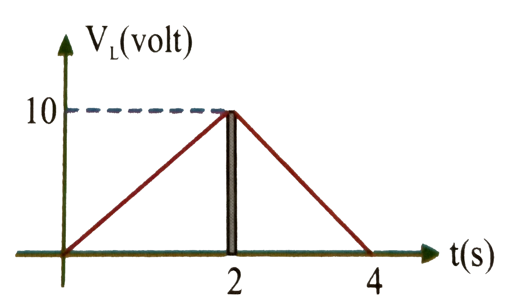
View SolutionThe potential difference across a `2 H` inductor as a function of time is shown in figure. At time `t=0`, current is zero
Current `t = 2` second is
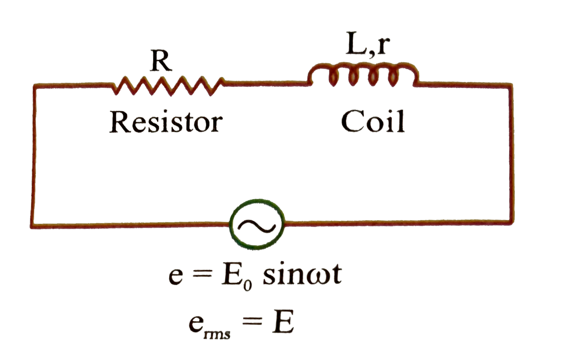
View SolutionFor the circuit shown in the figure the rms value of voltage across `R` and coil are `E_(1)` and `E_(2)` respectively.
The power (thermal) developed across the coil is
View SolutionA bulb is rated at `100V`, `100W`. It can be treated as a resistor. Find out the inductance of an inductor (called choke coil) that should be connected in series with the bulb at its rated power with the help of an ac source of `200V` and `50Hz`.
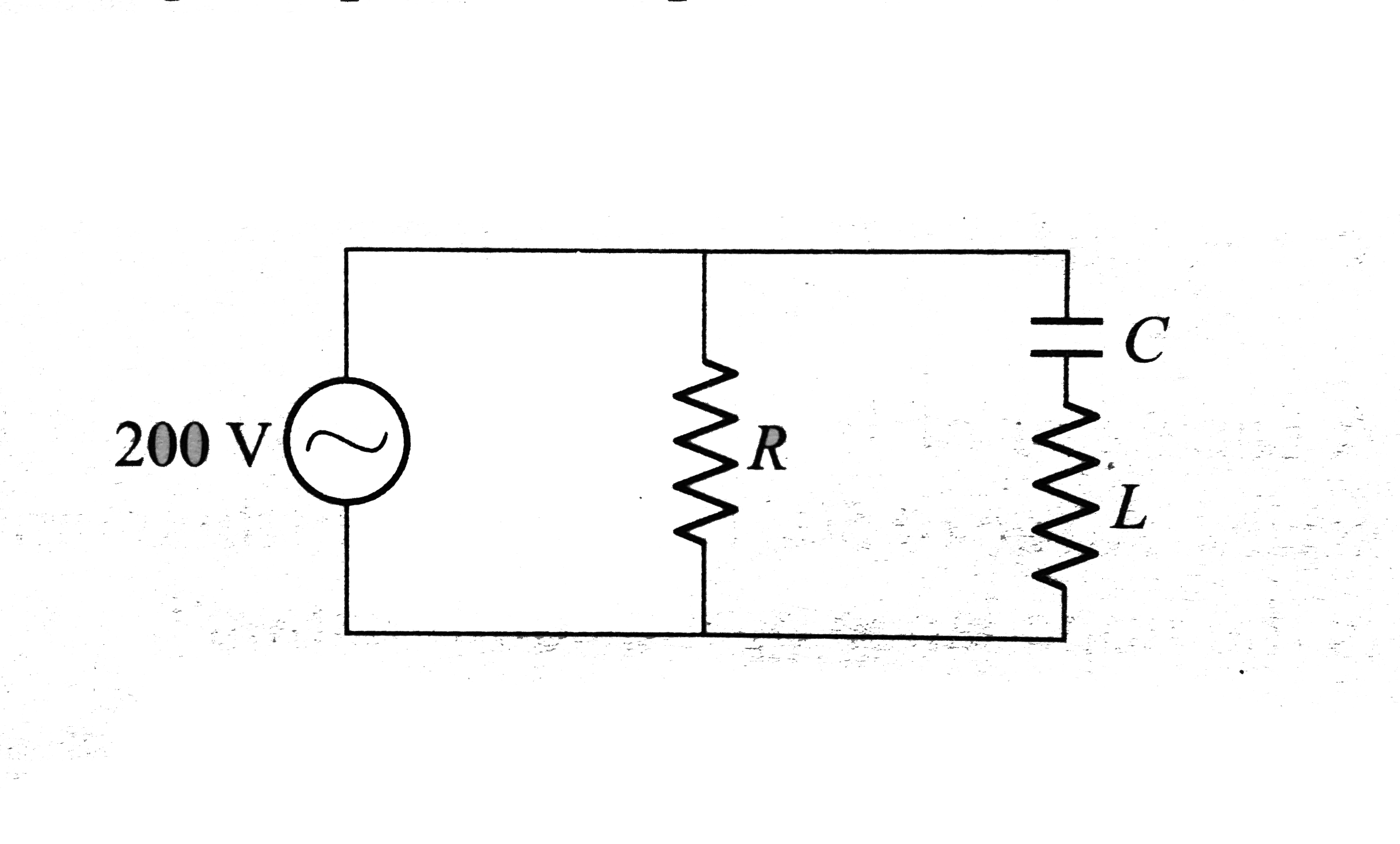
View SolutionIn the circuit shown in fig. `X_(C ) = 100 Omega,(X_L)=200 Omega and R=100 Omega`. The effective current through the source is
View SolutionWhen the rms voltages `V_(L), V_(C )` and `V_(R )` are measured respectively across the inductor `L`, the capacitor `C` and the resistor `R` in a series `LCR` circuit connected to an `AC` source, it is found that the ratio `V_(L) : V_(C ) : V_(R ) = 1 : 2 : 3`. If the rms voltage of the `AC` sources is `100 V`, the `V_(R )` is close to:
View SolutionA sinusoidal voltage `V (t) = 100 sin (500 t)` is applied across a pure inductance of `L = 0.02 H`. The current through the coil is :
View SolutionFor the `LCR` circuit, shown here, the current is observed to lead the applied voltage. An additional capacitor `C'`, when joined with the capacitor `C` present in the circuit, makes the power factor of the circuit unity. The capacitor `C'` must have been connected in:
View SolutionAn LCR curcuit is equivalent to a damped pendulum. In an LCR circuit the capacitor is charged to `(Q_0)` and then connected to the L ans R as shown below.
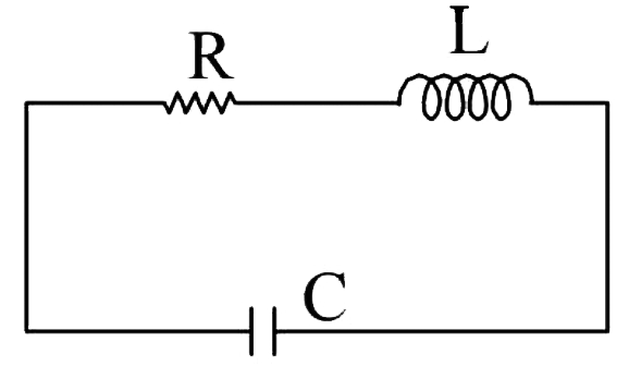
If a student plaots graphs of the square of maximum charge `(Q_(max)^(2))` on the capacitor with time (t) for two different values `L_(1) and L_(2) (L_(1)gtL_(2))` of L then which of the following represents this graph correclty? (plots are schematic and not drawn to scale).
View SolutionAn are lamp requires a direct current of 10A at 80V to function. If it is connected to a 220V(rms), 50 Hz AC supply, the series inductor needed for it to work is close to:
View Solution
LEVEL - III (C.W) questions and complete solutions for chapter ALTERNATING CURRENT of NARAYANA PHYSICS (HINGLISH) of Class 12