Complete Solutions to LEVEL - V of chapter ALTERNATING CURRENT of Class 12 book with complete answers and questions
| Class 12 | PHYSICS |
| Chapter | ALTERNATING CURRENT |
| NARAYANA | LEVEL - V |
| Number Of Questions | 83 |
| Academic Year | 2023-24 |
The value of current in two series `LCR` circuits at resonance is same when connected across a sinusodial voltage source. Then:
View SolutionThe series `RLC` circuit in resonance is called:
View SolutionIn a series R-L-C circuit, the frequency of the source is half of the resonance frequency. The nature of the circuit will be
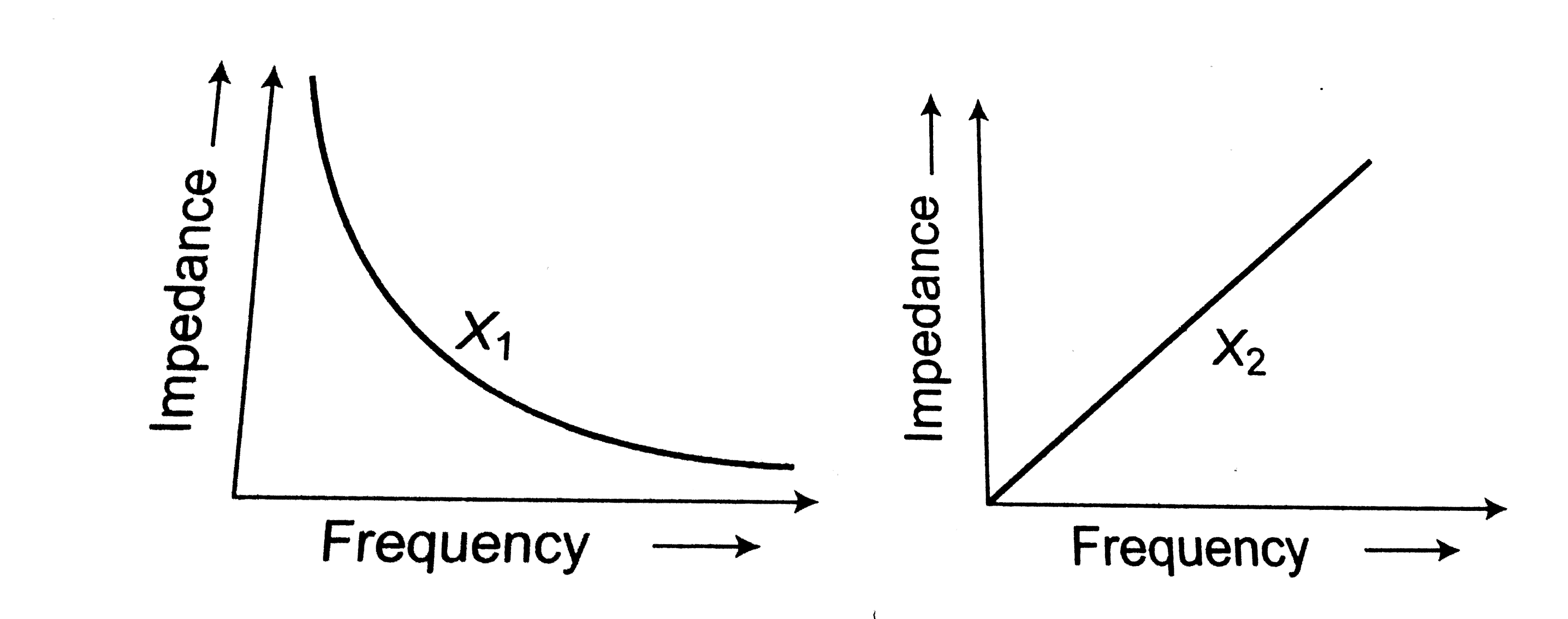
View SolutionThe graphs given below depict the dependence of two reactive impedences `X_(1)` and `X_(2)` on the frequency of the alternating e.m.f. applied individually to them. We can then say that
View SolutionIn which of the following electrical applianes will `AC` fail to function where `DC` is normally used?
View SolutionInstantaneous values of current and e.m.f in an AC circuit are `I=I//sqrt(2)sin 314` tamp and `E=sqrt(2)sin(314t-pi//6)V` respectively. The phase difference between `E` and `I` will be
View SolutionThe rms value of an ac of 50Hz is 10A. The time taken by an alternating current in reaching from zero to maximum value and the peak value will be
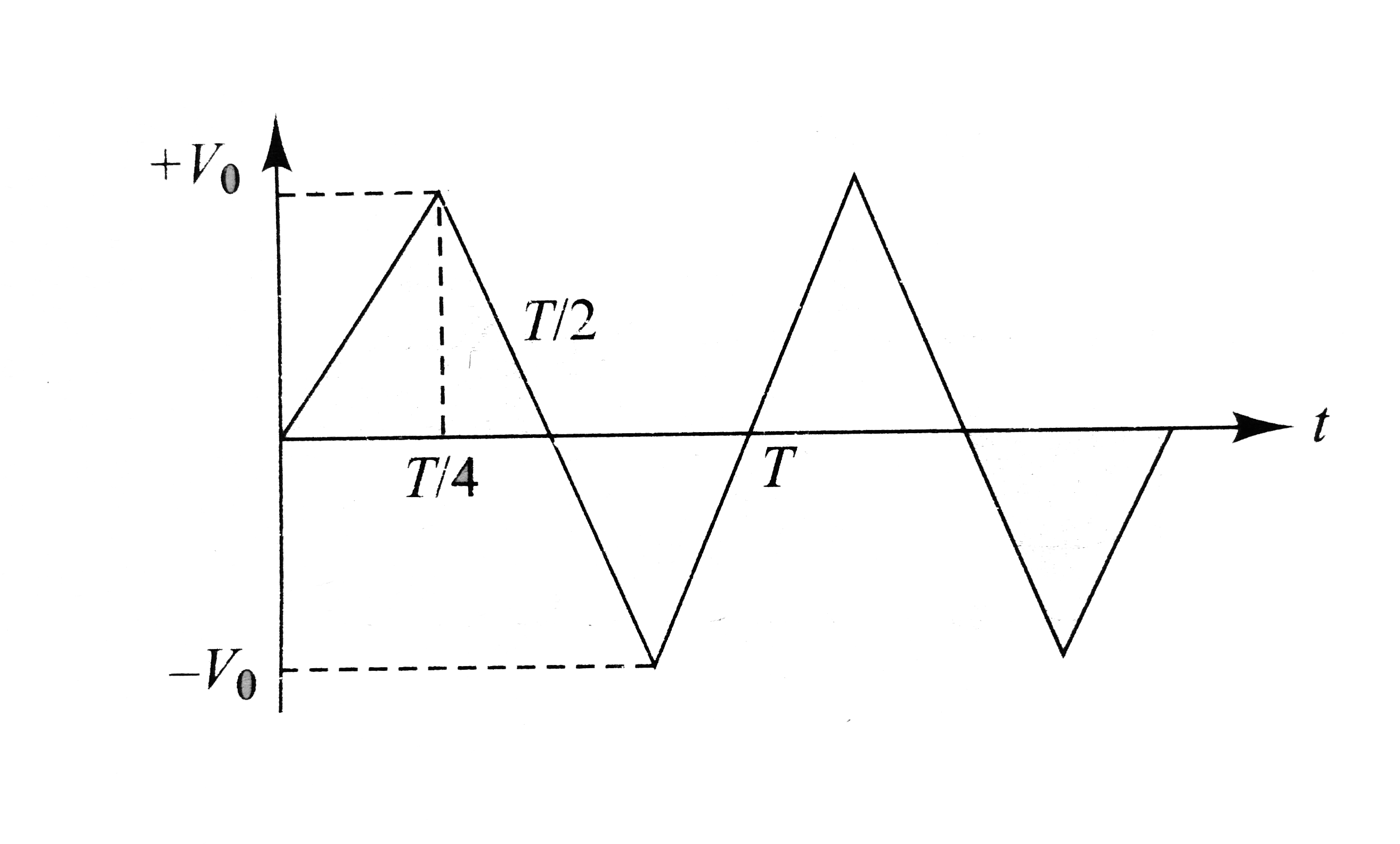
View SolutionThe voltage time (V-t) graoh for triangular wave having peak value `(V_0)` is as shown in fig.
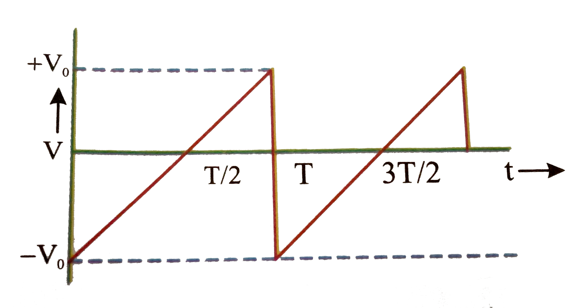
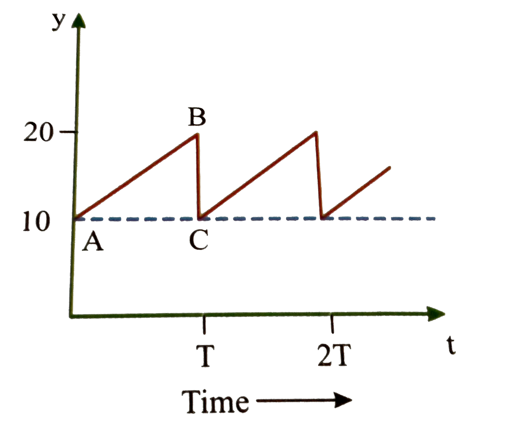
View SolutionThe average value for the saw-tooth voltage of peak value of `V_(0)` over half the cycle as shown in figure is
View SolutionAn alternating voltage is given by: `e = e_(1) sin omega t + e_(2) cos omega t`. Then the root mean square value of voltage is given by:
View SolutionIf `i= t^(2), 0 lt t lt T` then `r.m.s.` value of current is
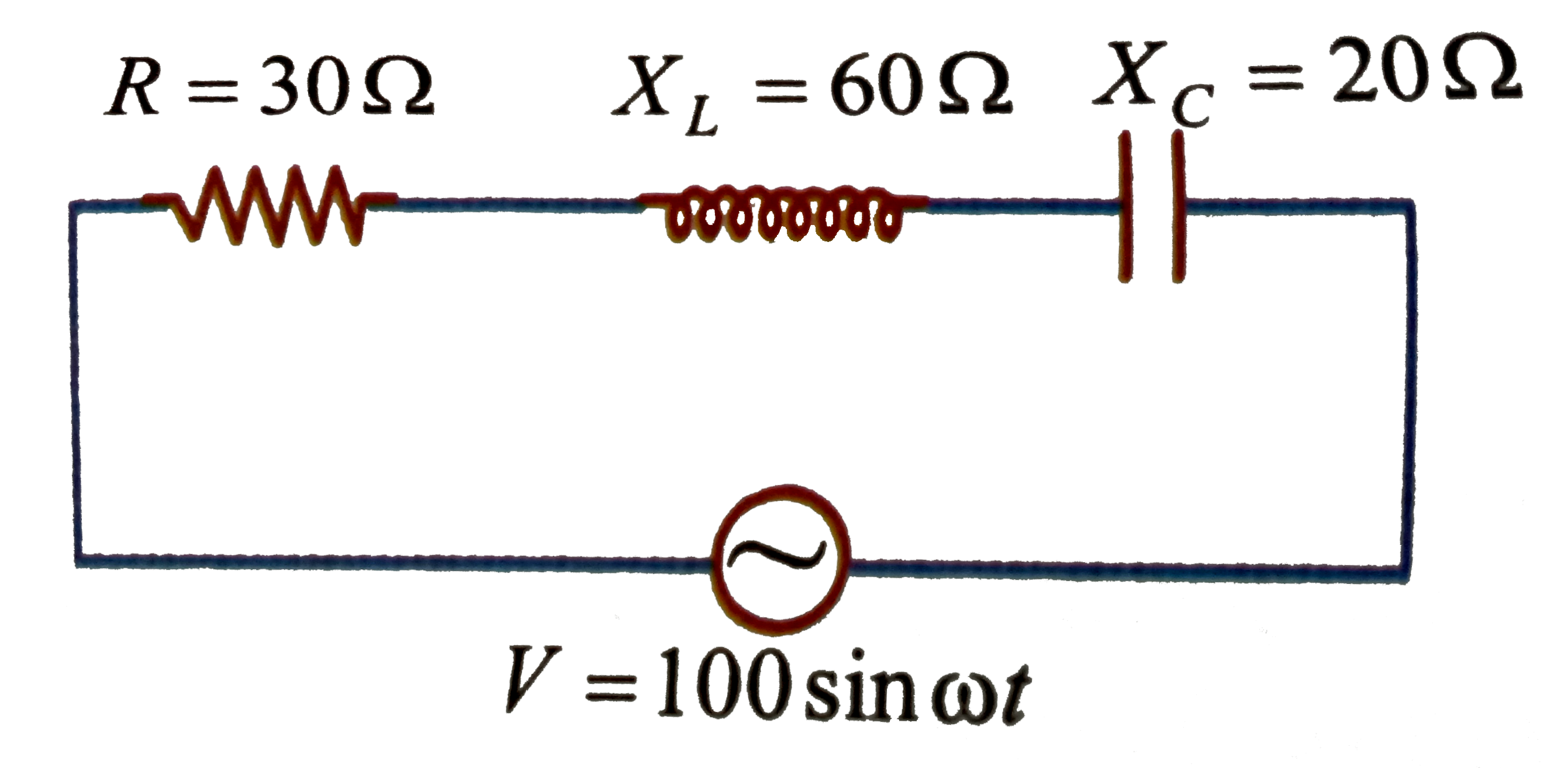
View SolutionAn alternating voltage `V = 100 sin omega t` is applied across an `LCR` circuit as shown. At the instant when voltage drop across source is `50 sqrt(3)` volts then at that instant
`R = 30 Omega" "X_(L ) = 60 Omega" "X_(C ) = 20 Omega`
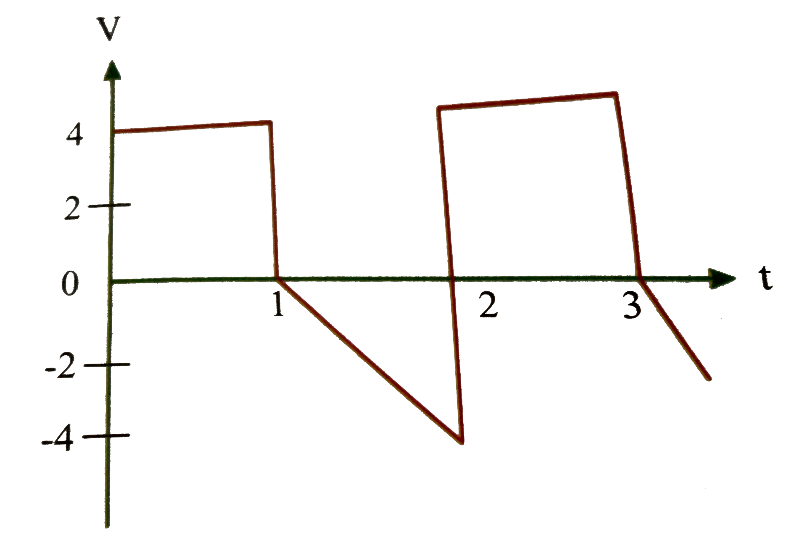
View SolutionThe rms and the average value of the voltage wave shown in figure are
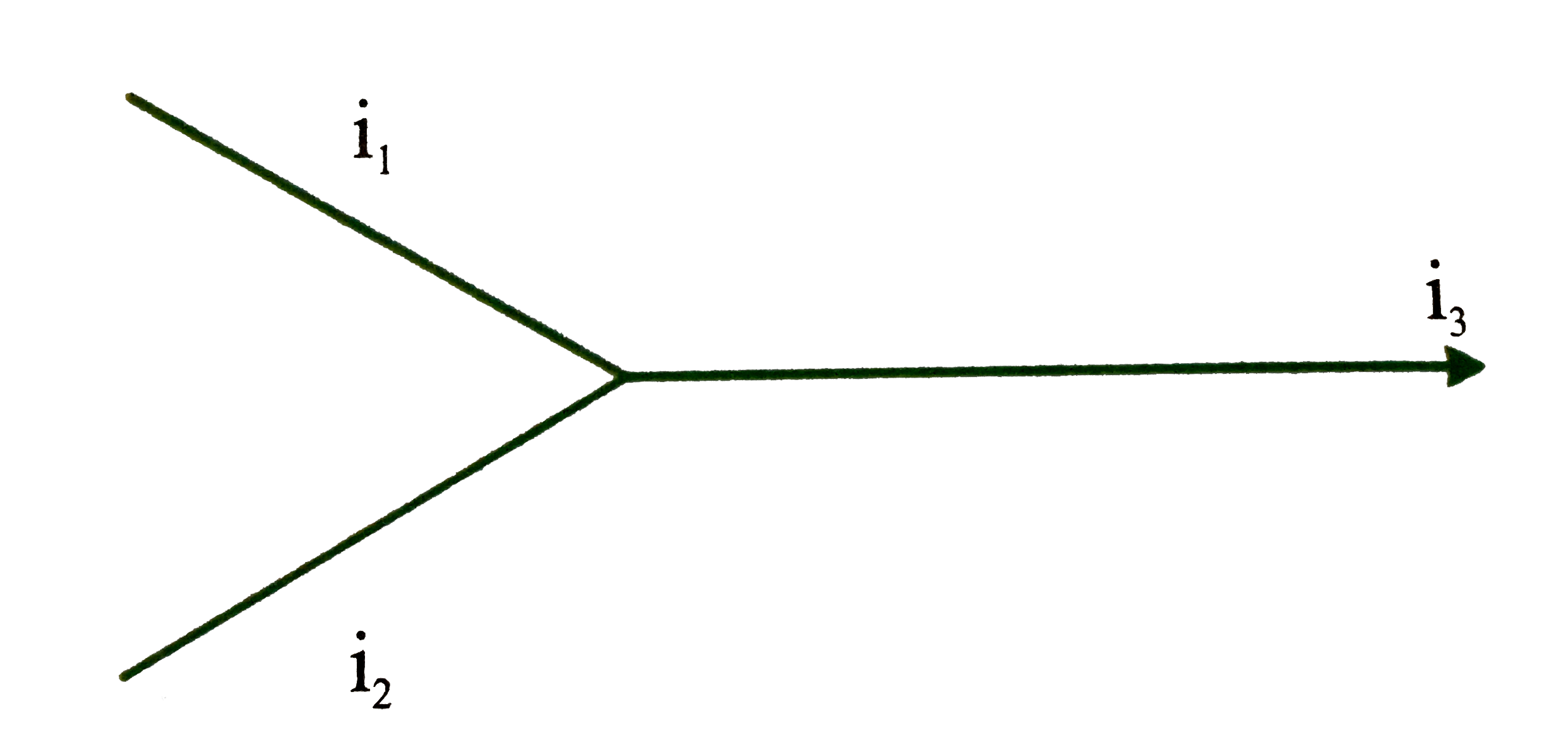
View SolutionIf `i_(1) = i_(0) sin (omega t), i_(2) = i_(0_(2)) sin (omega t + phi)`, then `i_(3) =`
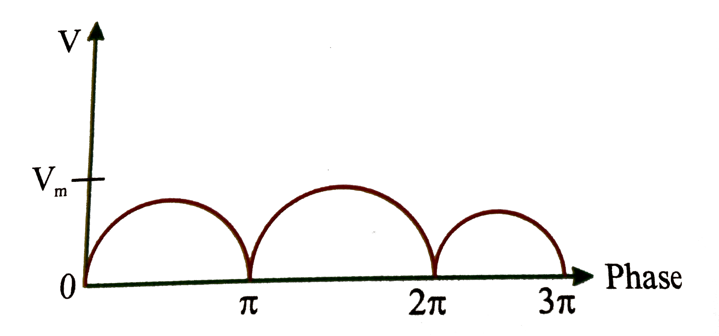
View SolutionThe average and effective values for the waveshaphe shown in figure are:
View SolutionCalculate the reading which will be given by a hot-wire voltmeter if it is connected across the terminals of generator whose voltage waveform is represented by
`v = 200 sin omega t + 100 sin 3 omega t + 50 sin omega t`
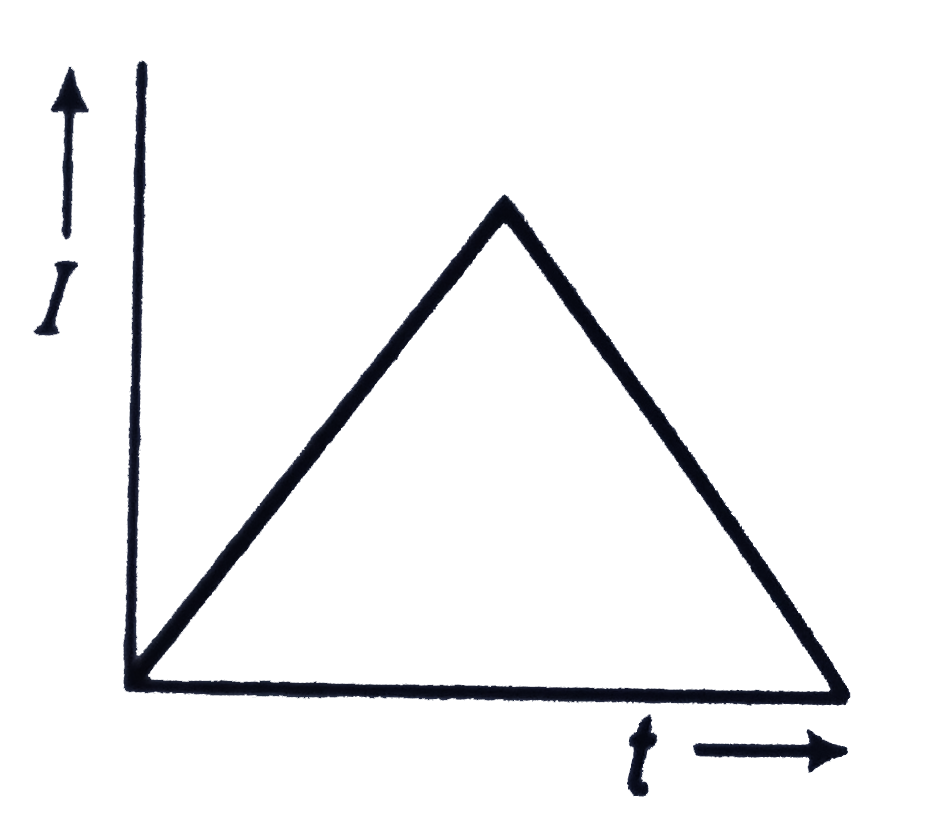
View SolutionAn alternating current `I` in an inductance coil varies with time `t` according to the graph as shown: Which one of the following graph gives the variation of voltage with time?
View SolutionFind the rms and average value of the wavefrom shown in figure
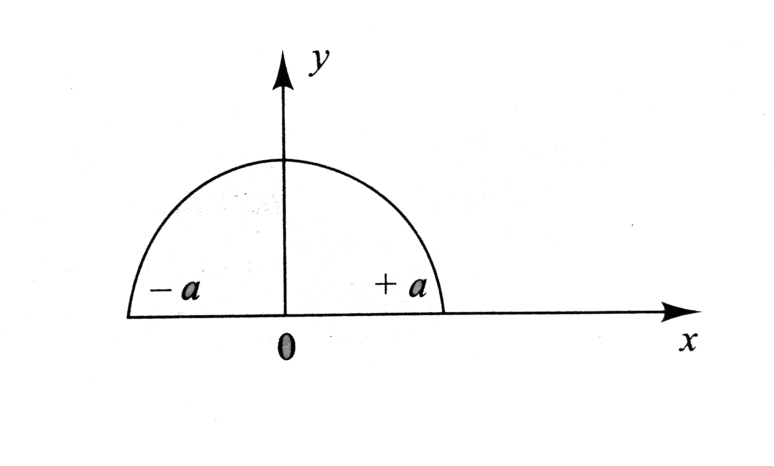
View SolutionDetermine the rms value of a semi-circular current wave which has a maximum value of a.
View SolutionAn electric bulb is designed to operate at `12` volts `DC`. If this bulb is connected to an AC source and gives normal brightness, what would be the peak voltage of the source?
View SolutionThe current in a discharging `LR` circuit is given by `I = i_0 e^(-t/tau)` where `tau` is the time constant of the circuit. Calculate the rms current for the period `t = 0` to `t = tau`.
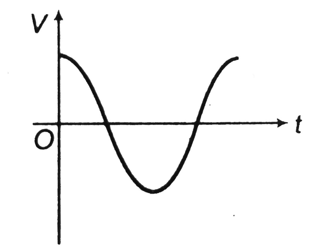
View SolutionThe figure represents the voltage applied across a pure inductor. The diagram which correctly represents the variation of curent `i` with time `t` is given by
 .
.
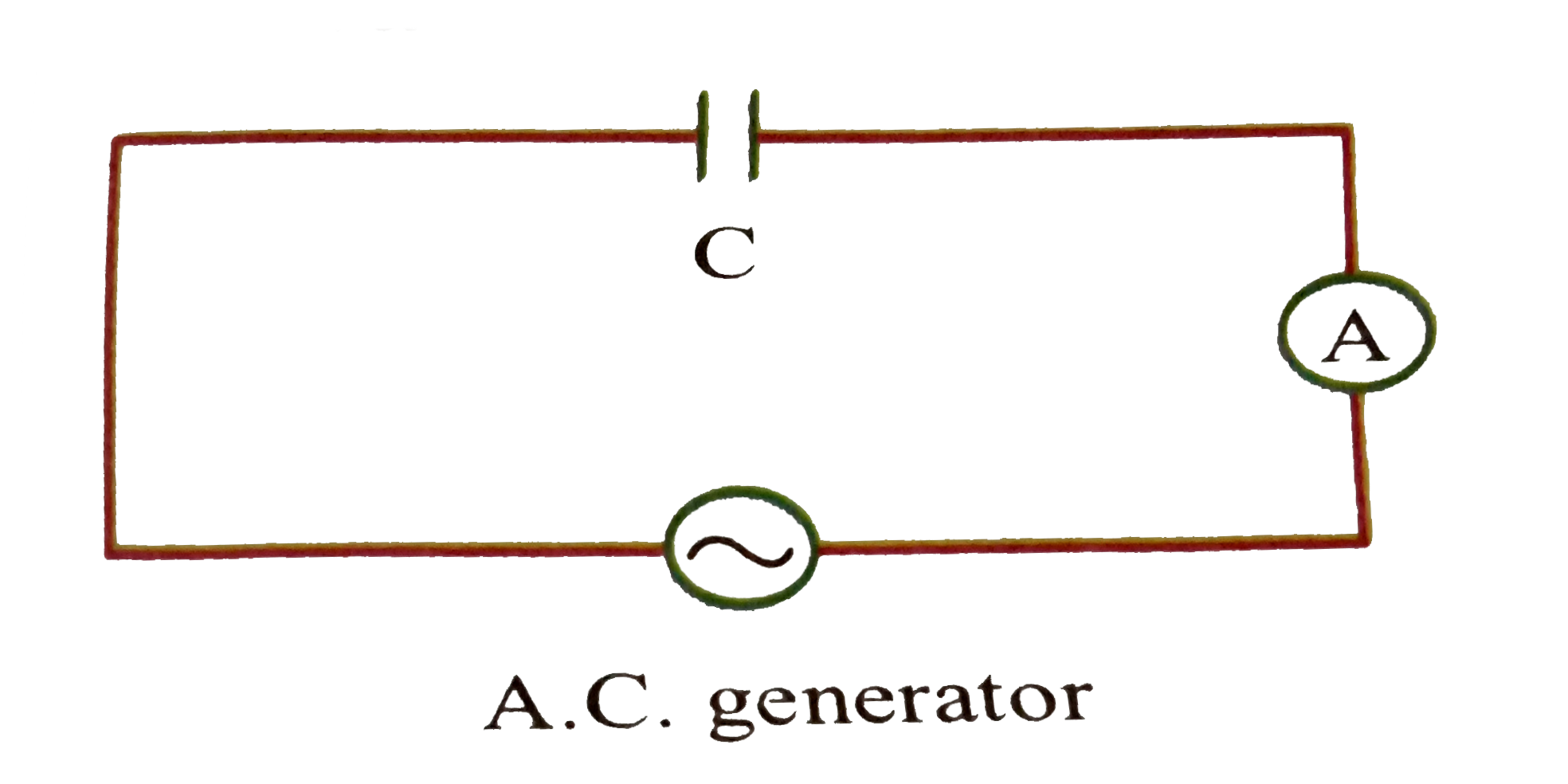
View SolutionA constant voltage at different frequencies is applied across a capacitance `C` as shown in the figure. Which of the following graphs correctly depicts the variation of current with frequency
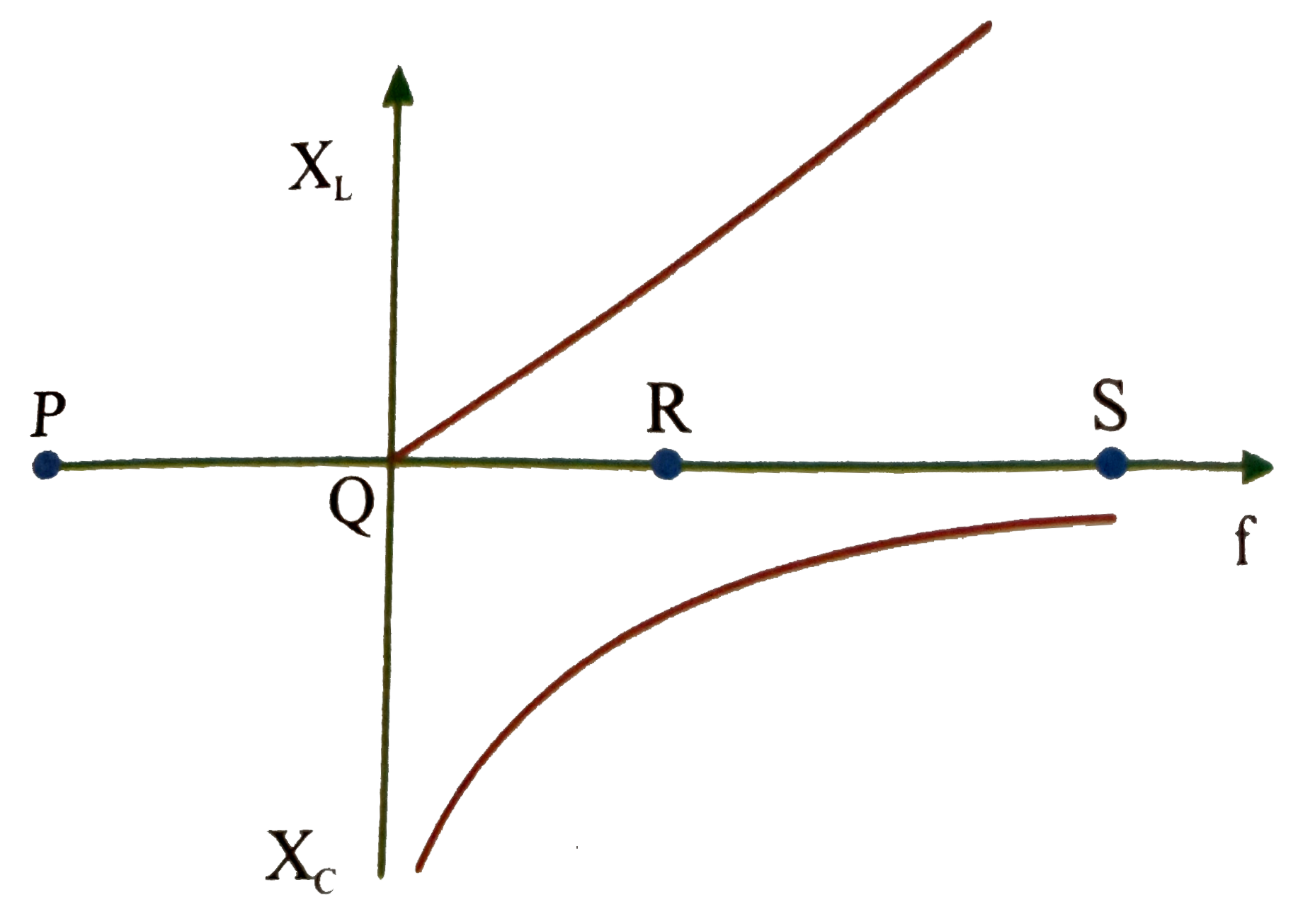
View SolutionThe resonance point in `X_(L) - f` and `X_(C ) - f` curves is
View SolutionWhen `100 V` DC is applied across a solenoid, a current of `1.0 A` flows in it. When `100 V` AC is applied across the same coil. The current drops to `0.5A`. If the frequency of the ac source is `50 Hz`, the impedance and inductance of the solenoid are
View SolutionA coil having an inductance of `1//pi` henry is connected in series with a resistance of `300 Omega`. If 20 volt from a 200 cycle source are impressed across the combination, the value of the phase angle between the voltage and the current is :
View SolutionIn a circuit containing an inductance of zero resistance, the current leads the applied a.c. voltage by a phase angle at
View SolutionIn `RLC` circuit, at a frequency `v`, the potential difference across each device are `(Delta V_(R))_("max") = 8.8 V, (Delta V_(L))_("max") = 2.6 V` and `(Delta V_(C ))_("max") = 7.4 V`. The composed potential difference `(Delta V_(C ) + Delta V_(L))_("max")` across inductor and capacitor is
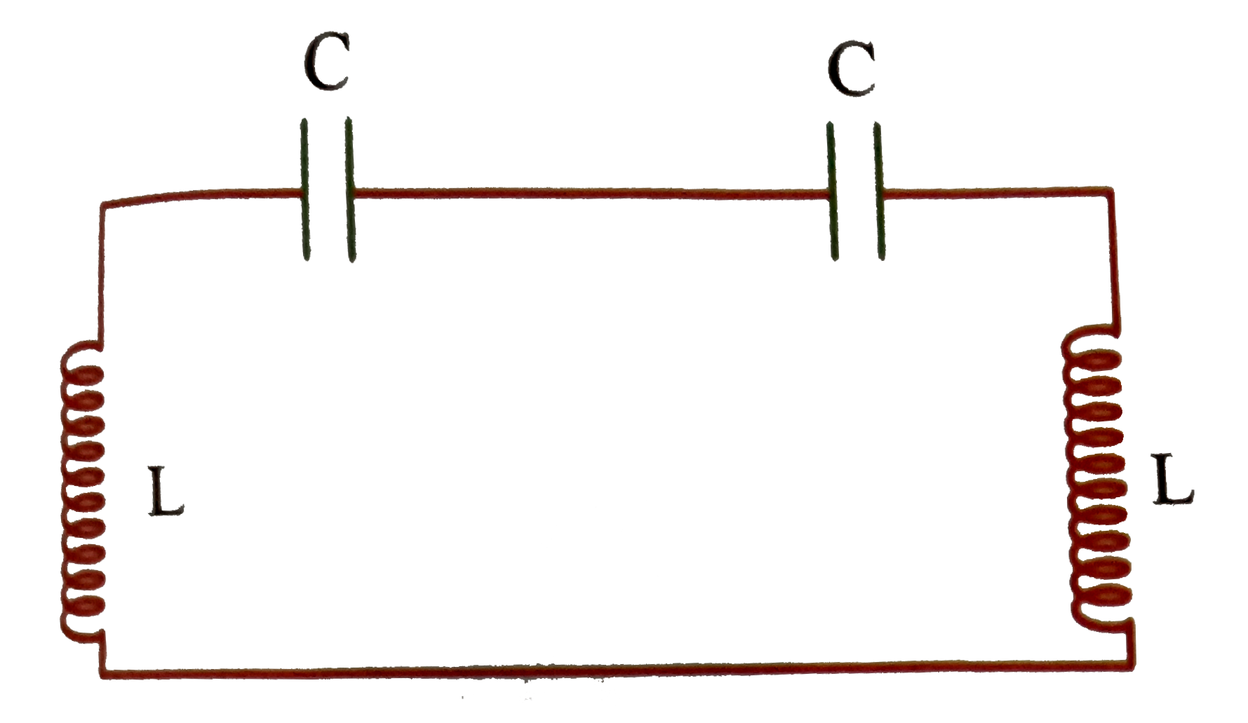
View SolutionThe natural frequency of the circuit shown in the figure is
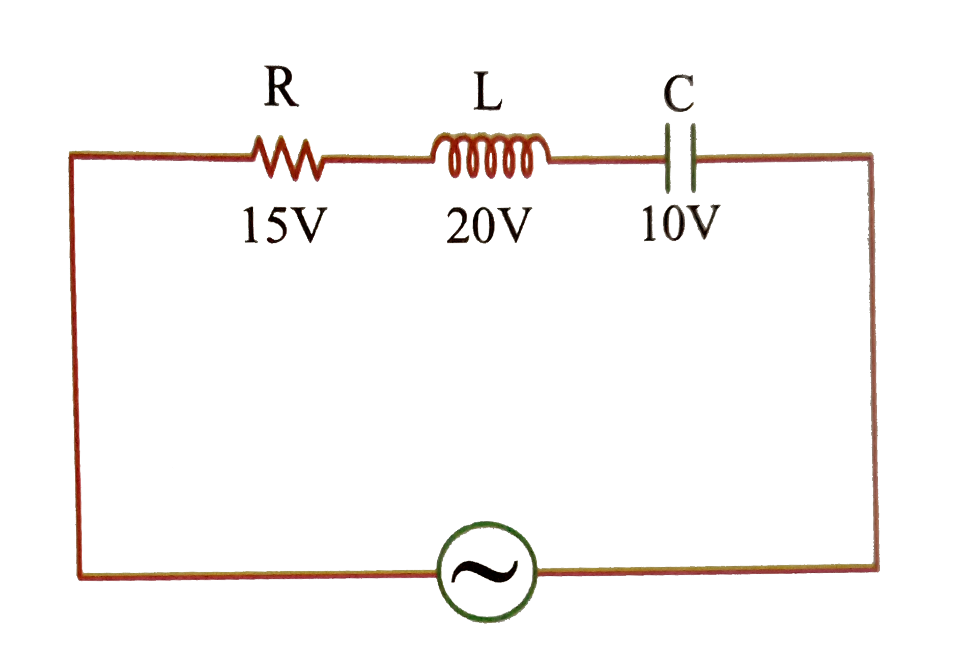
View SolutionIf the phase difference between voltage and current is `pi//6` and the resistance in the circuit is `sqrt(300) Omega`, then the impedance of the circuit will be
View SolutionIn the circuit as shown in the figure, if value of `R = 60 Omega`, then the current flowing through the condenser will be
View SolutionThe power in ac circuit is given by `P=E_(rms)I_(rms)cosphi`. The vale of cos phi in series LCR circuit at resonance is:
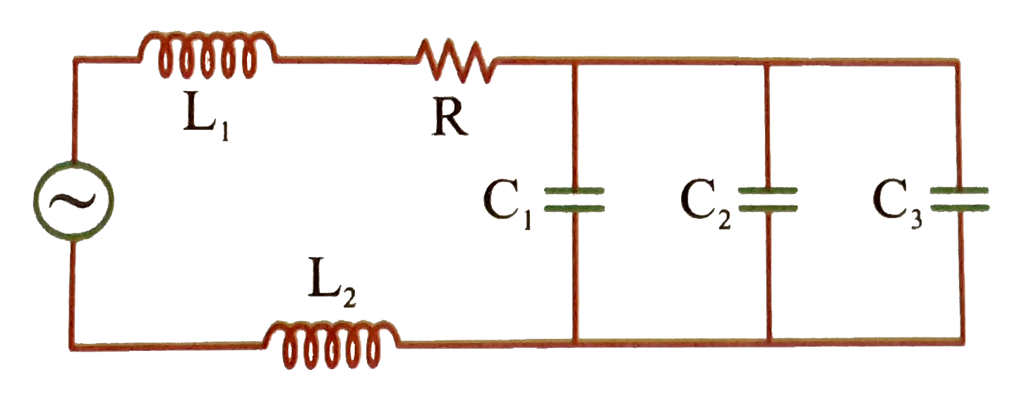
View SolutionA generator with an adjustable frequency of oscillaton is connected to resistance, `R = 1000 Omega`, inductance, `L_(1) = 1.7 mH` and `L_(2) = 2.3 mH` and capacitance, `C_(1) = 4 mu F, C_(2) = 2.5 mu F` and `C_(3) = 3.5 mu F`. The resonant angular frequency of the circuit is
View SolutionIn the a.c circuit shown in figure, the supply voltage has a constant r.m.s value but variable frquency f. Resonance frequency is
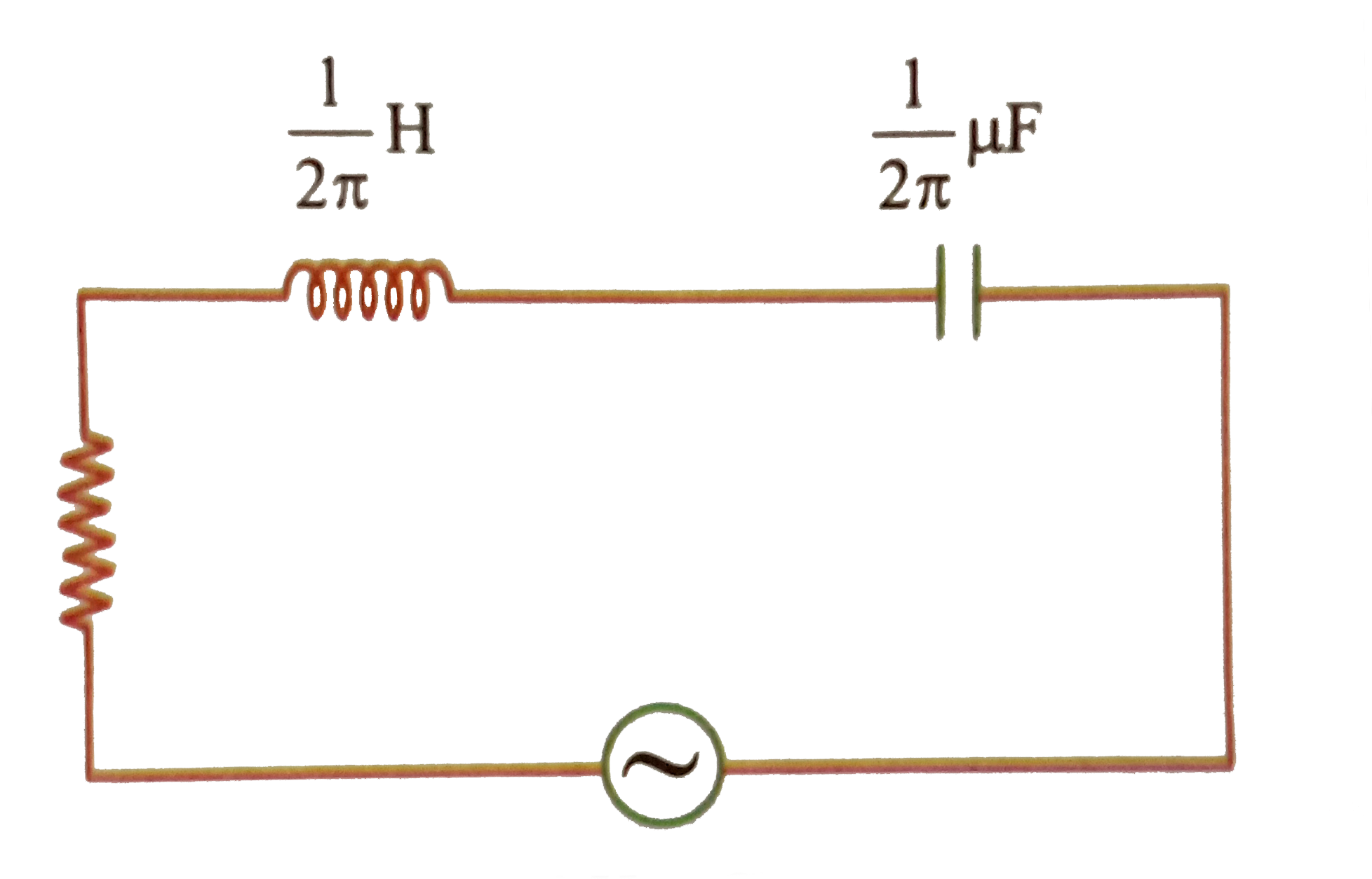
View Solutionin a LCR circuit capacitance is chagned from C to 2C. For the resomat frequency to remain unchaged, the inductance should be chagned from L to
View SolutionIn an `AC` circuit, `V` and `I` are given by `V=100sin(100t)volts, I=100sin(100t+(pi)/3)mA`. The power dissipated in circuit is
View SolutionA series combination of `R,LC` is connected to an a.c source. If the resistance is `3 Omega` and the reactance is `4 Omega`, the power factor of the circuit is
View SolutionIn an a.c. Circuit the voltage applied is `E=E_(0) sin (omega)t`. The resulting current in the circuit is `I=I_(0)sin((omega)t-(pi/2))`. The power consumption in the circuit is given by
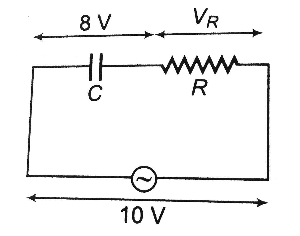
View SolutionIn a series `C-R` circuit shown in figureure, the applied voltage is `10 V` and the voltage across capacitor is found to`8 V`. The voltage across `R`, and the phase difference between current and the applied voltage will respectively be
 .
.
View SolutionAn inductor of inductance `L` and ressistor of resistance `R` are joined in series and connected by a source of frequency `omega`. Power dissipated in the circuit is
View SolutionPower loss in `AC` circuit will be minimum when
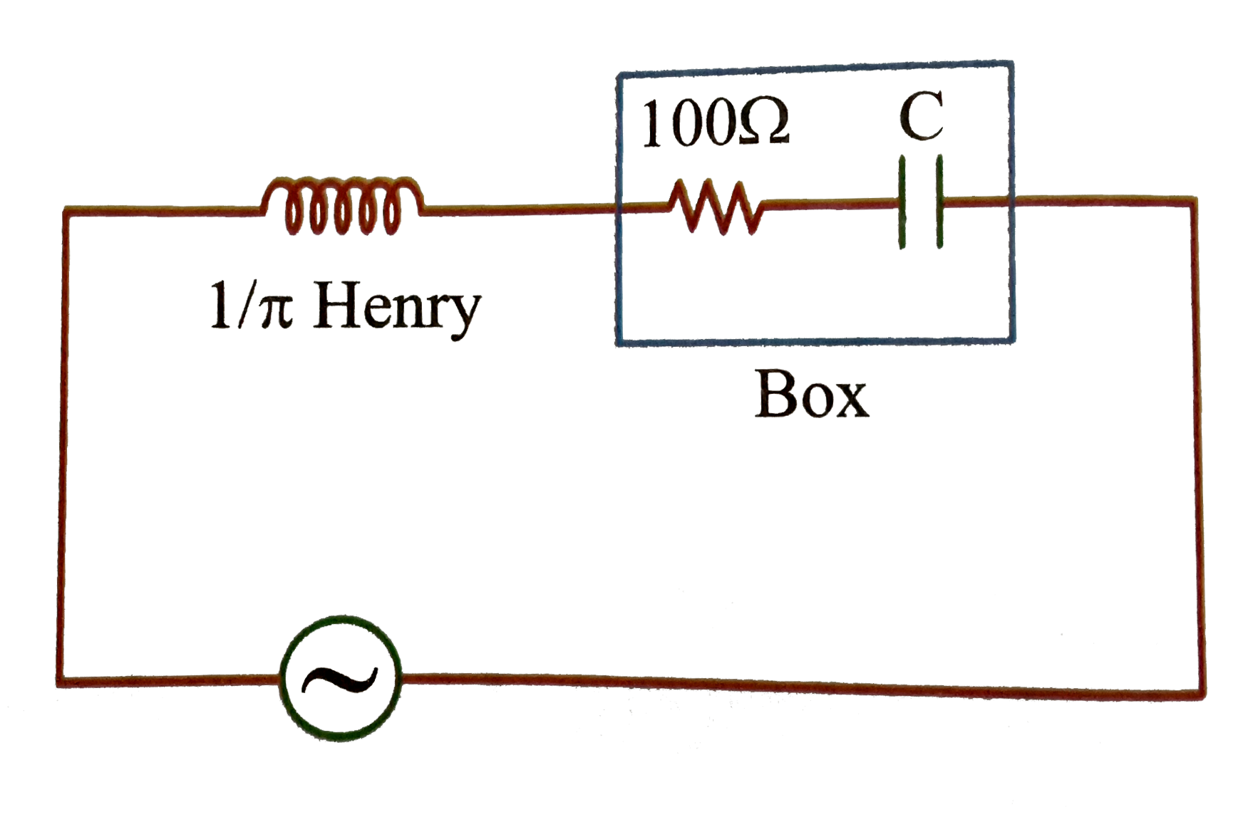
View SolutionIn the circuit, as shown in the figure, if the value of `R.M.S` current is 2.2 ampere, the power factor of the box is `(E = 220 V)`
View SolutionThe impedance of a sereis `RL` circuit is same as the series `RC` circuit when connected to the same `AC` source separately keeping the same resistance. The frequency of the source is
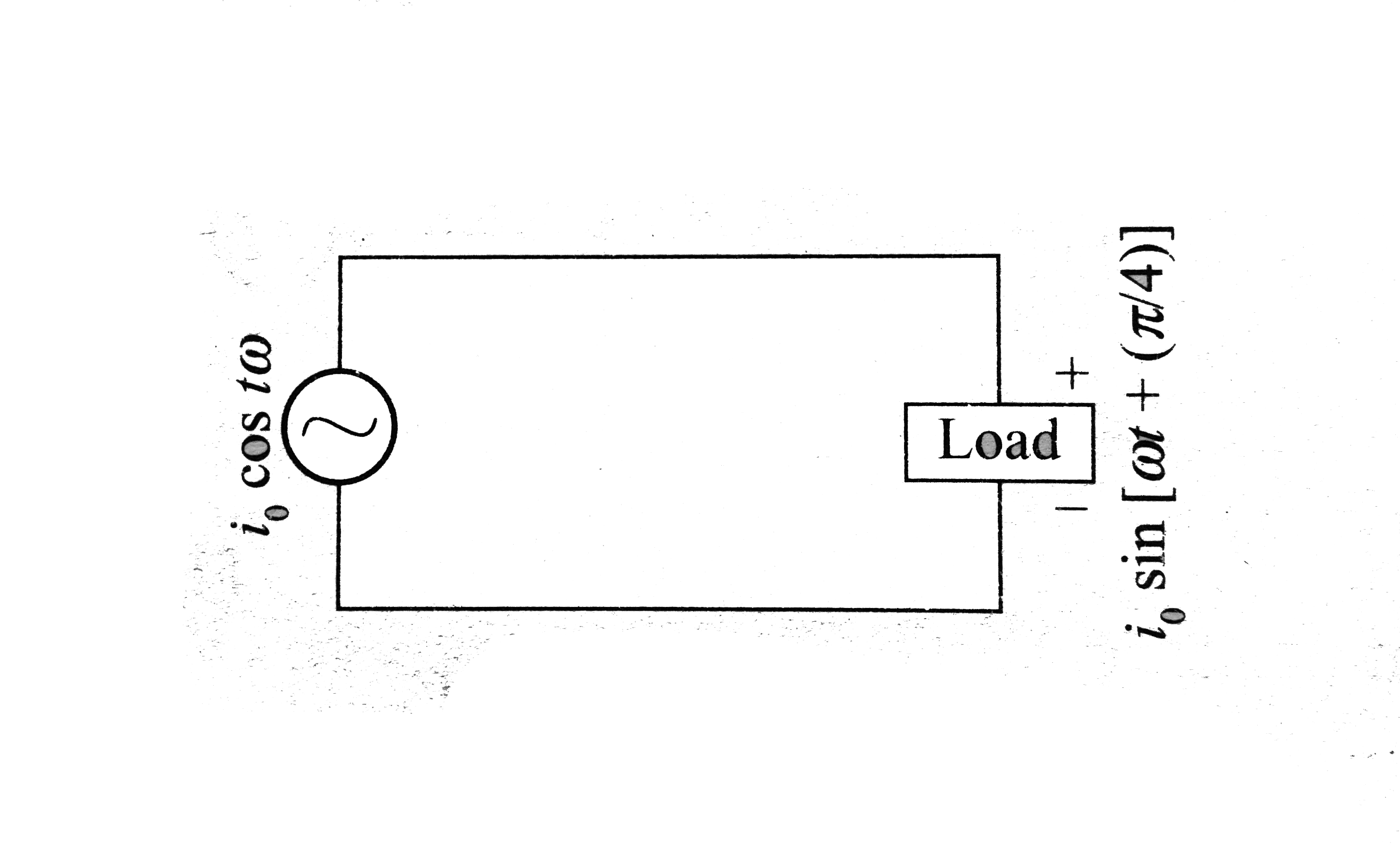
View SolutionA current source sends a current `I=(i_0) cos (omegat)`, When connected across an unknown load, it gives a voltages output of `v=v_(0)sin [omega t+(pi//4)]` across that load. Then the voltage across the current source may bebroaught in phase with the current through it by
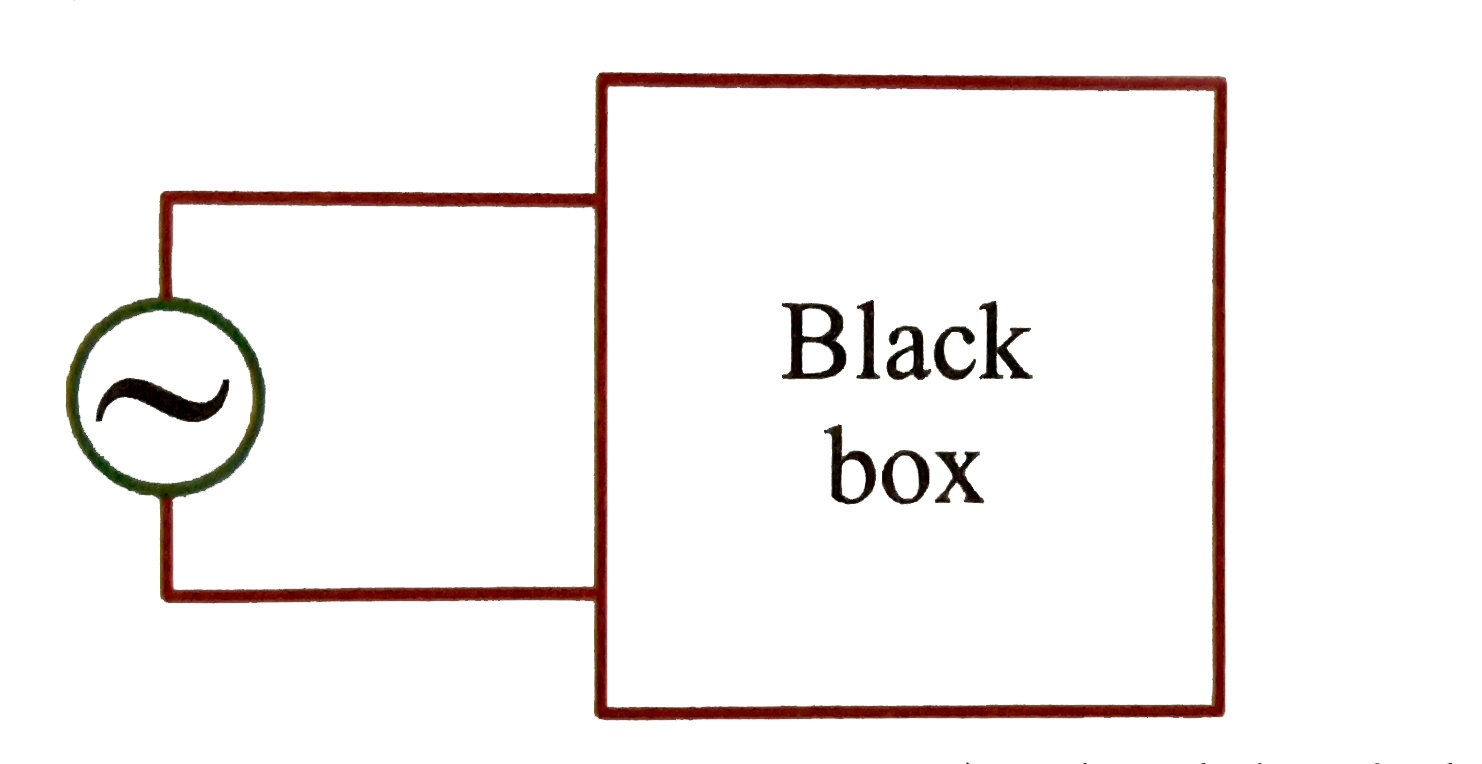
View SolutionA combination of elements is enclosed in a black box an the voltage and currents are measured across this black box. The expression for applied voltage, and the current flowing in it is `V = V_(0) sin omega t`,
`i = 2 sqrt(2) sin (omega + pi//4)` where `omega = 100 pi "rad"//"sec"` Then the wrong statement is
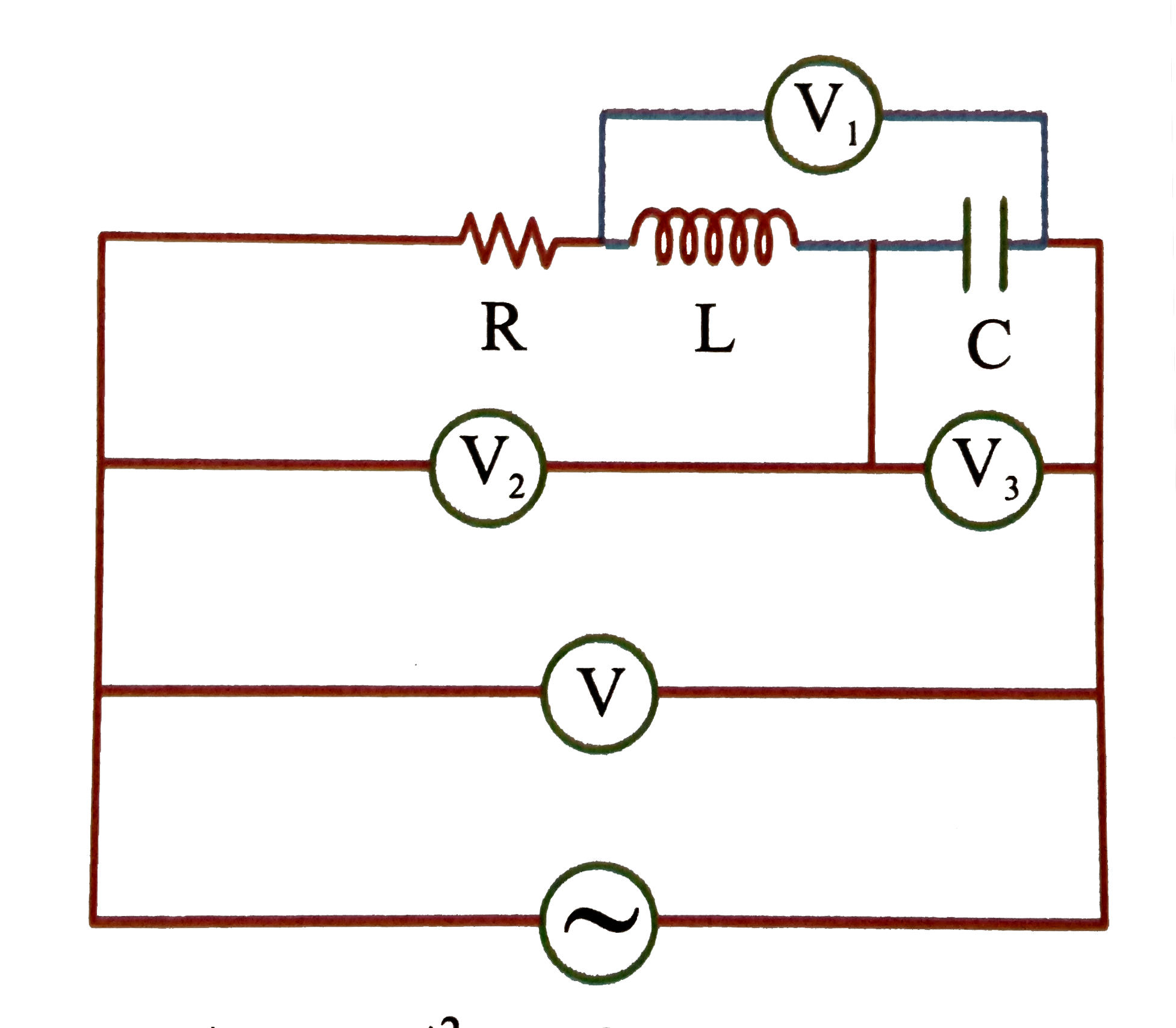
View SolutionA high impedance `AC` voltmeter is connected in turn across the inductor, the capacitor and the resistor in a series circuit having an `AC` source of `100 V` (rms) and gives the same reading in volts in each case. This reading is:
View SolutionIn a black box of unknown elements (L or R or any other combination), an ac voltage `E=E_(0) sin (omegat)+phi)` is applied and current in the circuit was found to be `I=(I_0) sin [ omega t + phi + (pi//4)]`. Then the unknown elements in the box may be
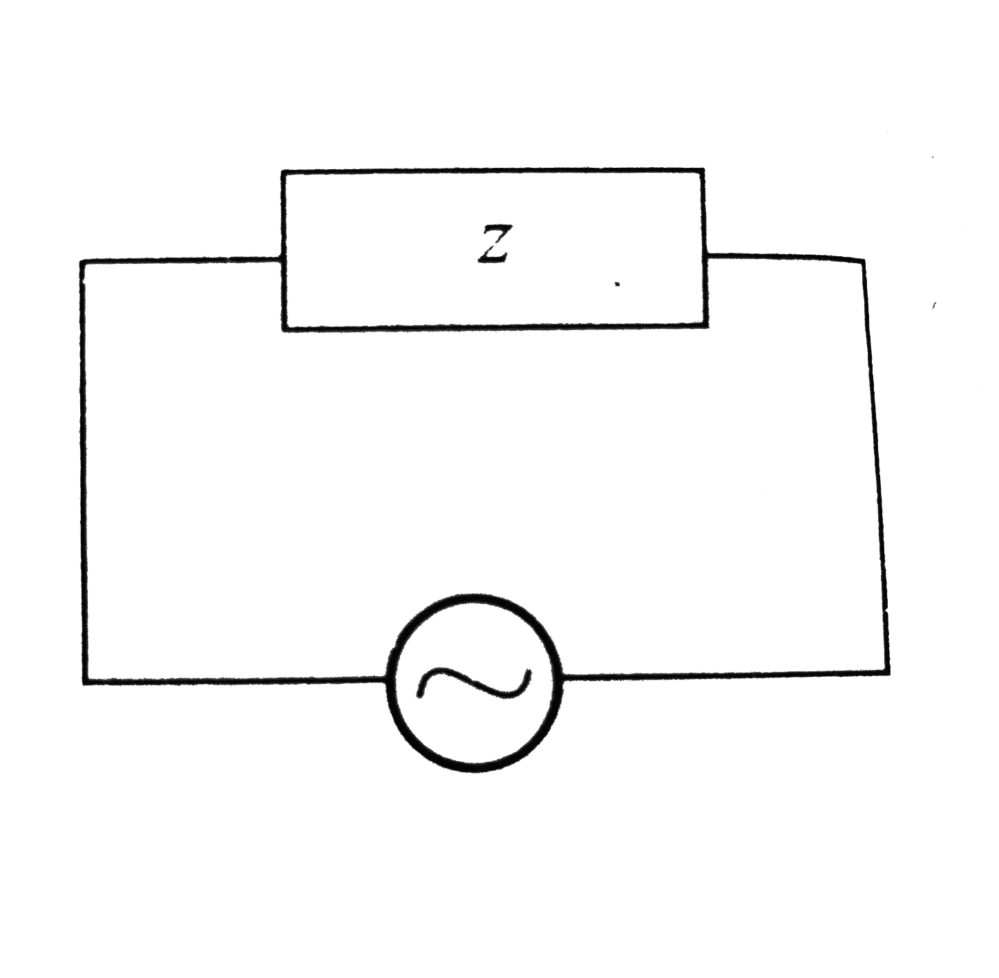
View SolutionA given alternating current has an rms value of 5.6 ampere. If this current flows in a circuit containing `10 Omega` of resistance in series with `20 Omega` of inductive reactance, the power consumed in the circuit will be
View SolutionIn an a.c circuit, `V` & I are given by `V = 100 sin (100 t)` volt.
`I = 100 sin (100 t + (pi)/(2)) mA`
The power dissipated in the circuit is:
View SolutionIn `R-L-C` series circuit, we have same current at angular frequencies `omega_(1)` and `omega_(2)`. The resonant frequency of circuit is
View SolutionA choke coil of resistance `R` and inductance `L` is connected to `A.C` sourceof frequency `f` and maximum voltage `V_(0)`. Then, the average power dissipated in the choke is proportional to:
View SolutionWhen two `A.C` generators of emfs `V_(1)` and `V_(2)` and same frequency connected in series, the emf across `A` and `B` is `(phi =` phase angle difference between the generators):

View SolutionAt resonance of the given series `R-L-C` circuit:
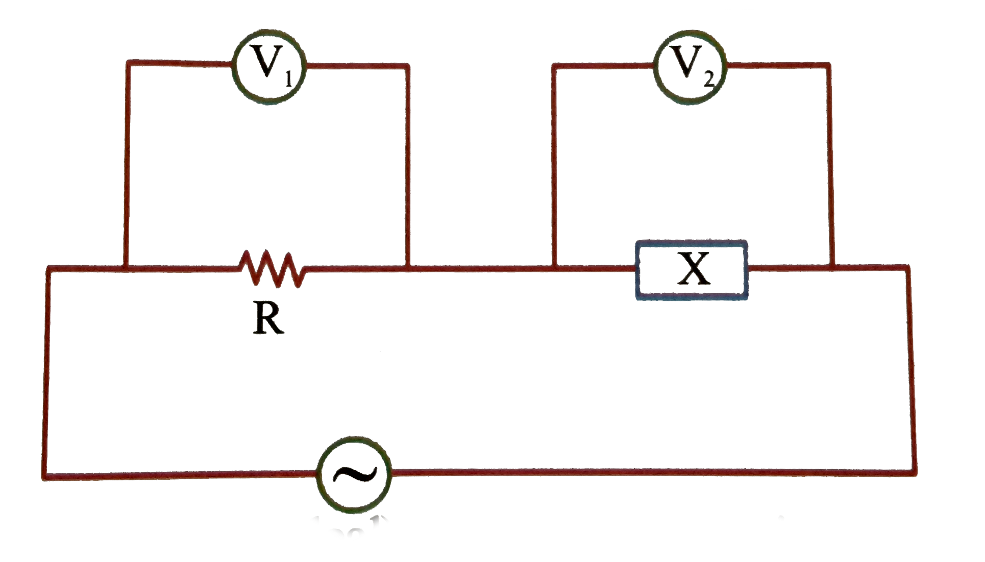
View SolutionIf the reading of the voltmeters vary with time as: `V_(1) = 20 sin omega t` and `V_(2) = - 20 cos (omega t + (pi)/(6))` then the unknown circuit element `x` is a:
View SolutionIn a series `LCR` circuit, at the frequencies `f_(1)` and `f_(2)` of `AC` source, the current amplitude falls to `(1)/(sqrt(2))` of the current amplitude at resonance. Then the value of `f_(2) - f_(1)` is
View SolutionIn the figure, which of the phasor diagrams represents `RLC` circuit driven at resonance?
View SolutionIn `LCR` circuit at resonance current in the circuit is `10 sqrt(2) A`. If tnow frequency of the source is changed such that now current lags by `45^(@)` that applied voltage in the circuit . Which of the following is correct.
View SolutionA pure resistive circuit element `X` when connected to an sinusoidal `AC` supply peak voltage `200 V` gives a peak current of `5A` which is in phase with the voltage. A second circuit element `Y`, when connected to the same `AC` supply also gives the same value of peak currrent but the current lags behind by `90^(0)`. If the series combination of `X` and `Y` is connected to the same supply. the rms value of current is
View SolutionAn `A.C` circuit contains a resistor `'R'` an inductor `'L'` and a capacitor `'C'` connected in series. When it is connected to an `A.C` generator of fixed output voltage and varialbe frequency, the current in the circuit is found to be leading the applied voltage `(pi)/(4)` read, when the frequency is `f_(1)`. when the frequency of the generator increased to `f_(2)` the current is found to be lagging behind the applied voltage by `(pi)/(4)` rad. The resonant frequency of the circuit is
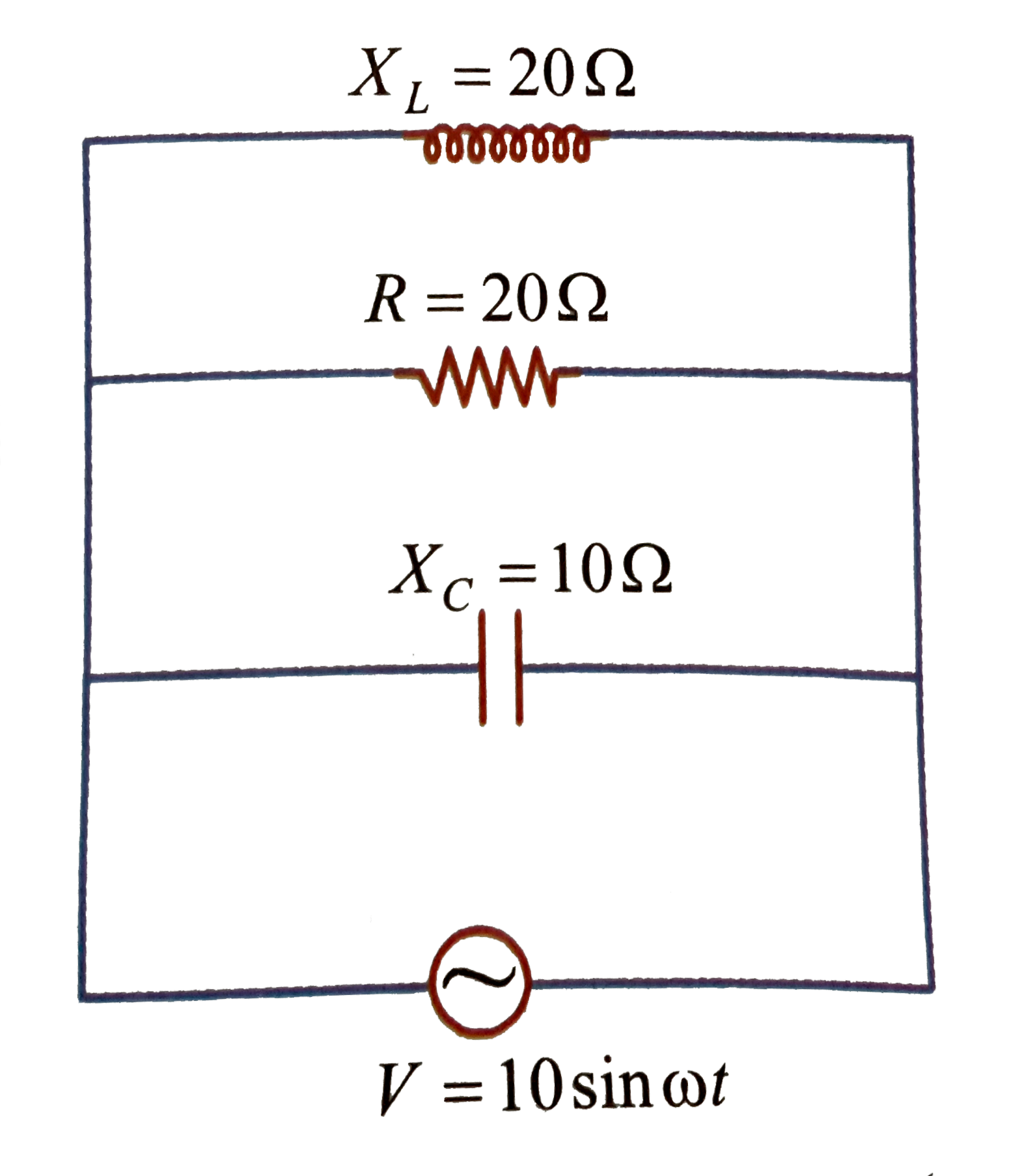
View SolutionAn alternative voltage `V = 10 sin omega t` (in volts) is applied across a parallel arrangement as shown current (in `A`) through the source is best described by
View SolutionA radio tuner has a frequency range from `500 kHz` to `5 MHz`. If its `LC` circuit has an effective inductance of `200 mu H`, what is the range of it varialbe capacitors? (Take `pi^(2) = 10 )`.
View SolutionIn a series `LCR` circuit the frequency of a `10 V`, `AC` voltage soure is adjusted in such a fashion that the reactance of the inductor meausers `15 Omega` and that of the capacitor `11 Omega`. If `R = 3 Omega`, the potentail difference across the series combination of `L` and `C`will be:
View SolutionA resistor of resistance `100 Omega` is connected to an `AC` source `epsilon = (12 V) sin (250 pi s^(-1))t`. Find the energy dissipated as heat during `t = 0` to `t = 1.0 ms`.
View SolutionA lamp consumes only `50%` of peak power in an `a.c.` circuit. What is the phase difference between the applied voltage and the circuit current
View SolutionVoltage and current for a circuit with two elements in series are expressed as
`V(t)=170sin(6280t+pi/3)volt`
`i(t)=8.5sin(6280t+pi/2)amp`
(a) Plot the two waveforms.
(b) Determine the frequency in Hz.
(c) Determine the power factor starting its nature.
(d) What are the values of the elements?
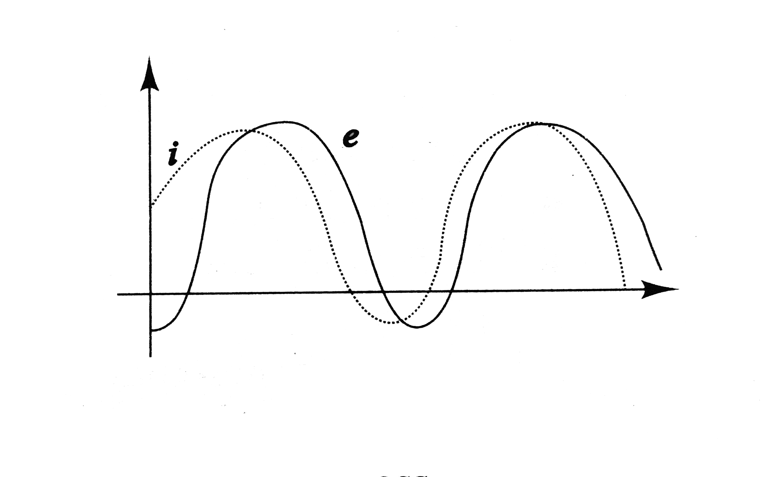
View SolutionWhen an ac source of emf`e=E_(0) sin (100 t)` is connected across a circuit, the phase difference between emf e and currnet I in the circuit is observed to be `(pi)//(4)` as shown in fig. If the circuit consists possibly only of R-C or R-C of L-R series, find the relationship find the relationship between the two elements.
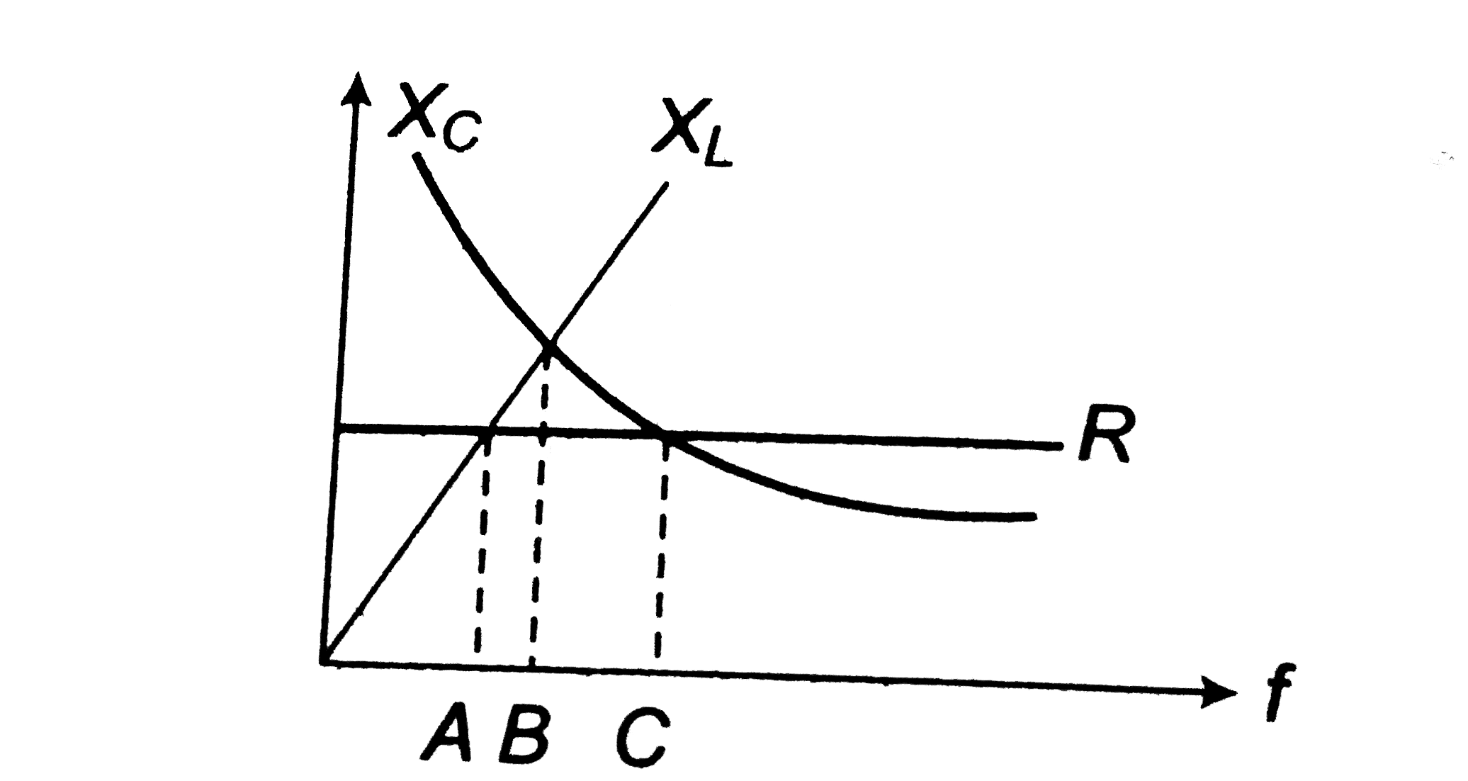
View SolutionThe figure shows variation of `R,X_(L)` and `X_(C)` with frequency `f` in a series `L,C,R` circuit. Then for what frequency point, the circuit is inductive ?
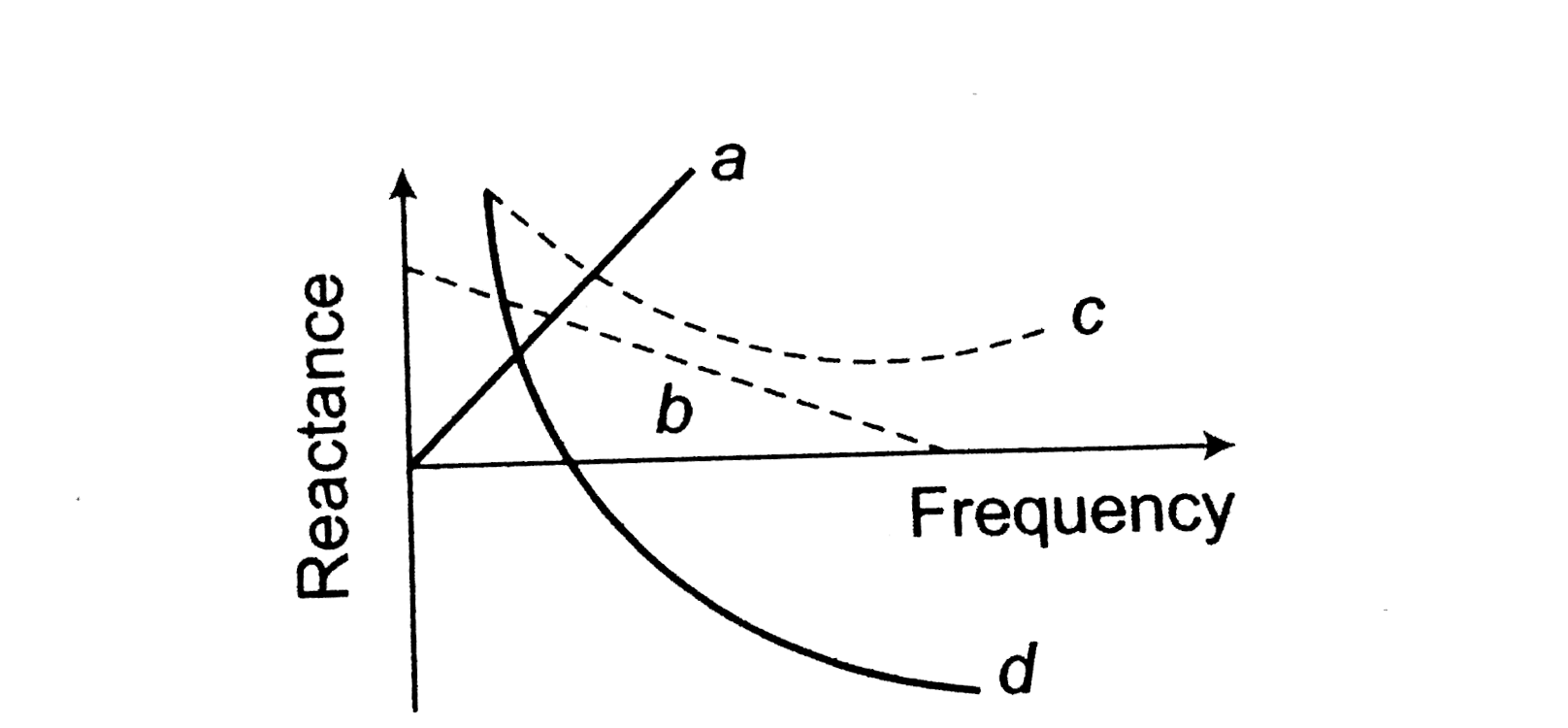
View SolutionWhich of the following plots may represent the reactance of a series `LC` combination?
View SolutionAn inductor-coil , a capacitor and an AC source of rms voltage `24 V` are connected in series. When the frequency of the source is varied, a maximum rms current of `6.0 A` is observed. If this inductor coil is connected to a battery of `emf 12 V` and internal resistance `4.0 Omega`, what will be the current?
View SolutionA circuit consisting of a capacitor and a coil in series is connected to the mains. Varying the capacitance of the capacitor, the heat power genergated in the coil was increased `n=1.7` times. How much `(` in per cent `)` was the value of ` cos varphi` changed in the process ?
View SolutionAn AC source producing `emf`
`epsilon = epsilon_0 [cos(100 pi s^(-1)) t + cos (500 pi s^(-1))t]`
is connected in series with a capacitor and a resistor. The steady-state current in the circuit is found to be
`I = i_1 cos [(100 pi s^(-1) t + varphi_1] + i_2 cos [(500 pi s^(-1))t +phi_2]`.
View SolutionIn the circuit shown in figureure the `AC` source gives a voltage `V=20cos(2000t)`. Neglecting source resistance, the voltmeter and and ammeter readings will be
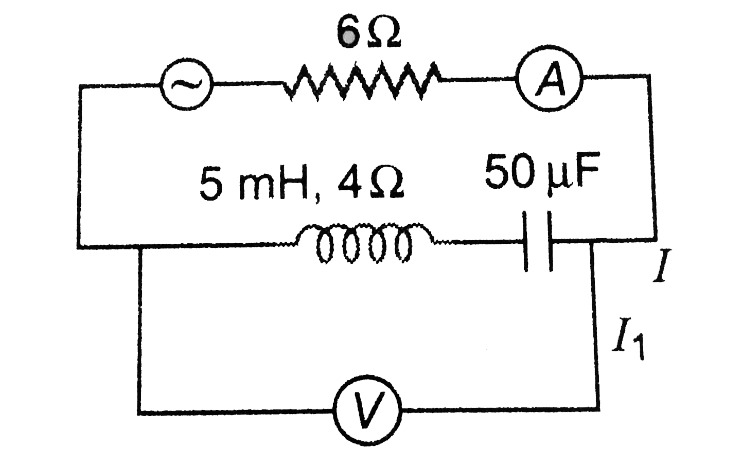 .
.
View SolutionIn figure `i_(1) = 10 e^(-2t) A, i_(2) = 4 A, v_(C ) = 3 e^(-2t) V`
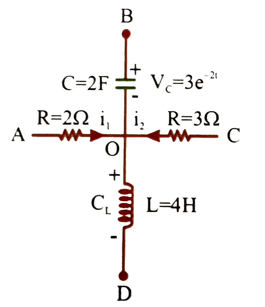
The current `i_(L)` is
View SolutionIn figure `i_(1) = 10 e^(-2t) A, i_(2) = 4 A, v_(C ) = 3 e^(-2t) V`
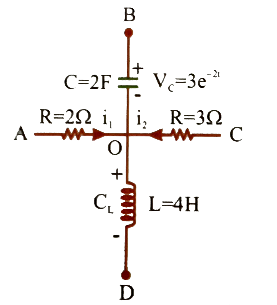
The variaton of current in the inductor with time can be repesented as :
View SolutionIn figure `i_(1) = 10 e^(-2t) A, i_(2) = 4 A, v_(C ) = 3 e^(-2t) V`
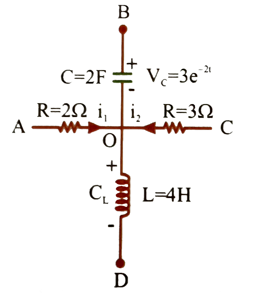
The potential difference across inductor `V_(L)` is :
View SolutionIn figure `i_(1) = 10 e^(-2t) A, i_(2) = 4 A, v_(C ) = 3 e^(-2t) V`
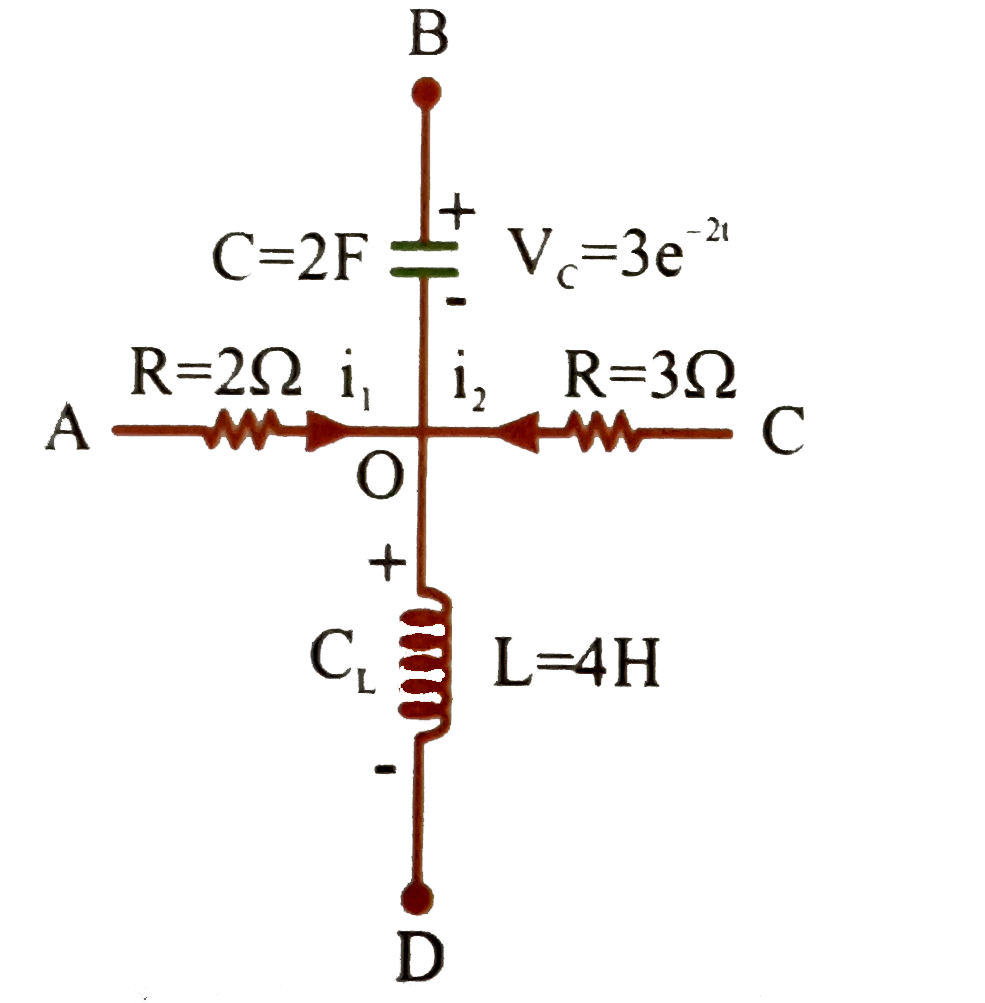
The variation of potential difference acorss `A` and `C` with time can be represented as
View SolutionIn figure `i_(1) = 10 e^(-2t) A, i_(2) = 4 A, v_(C ) = 3 e^(-2t) V`
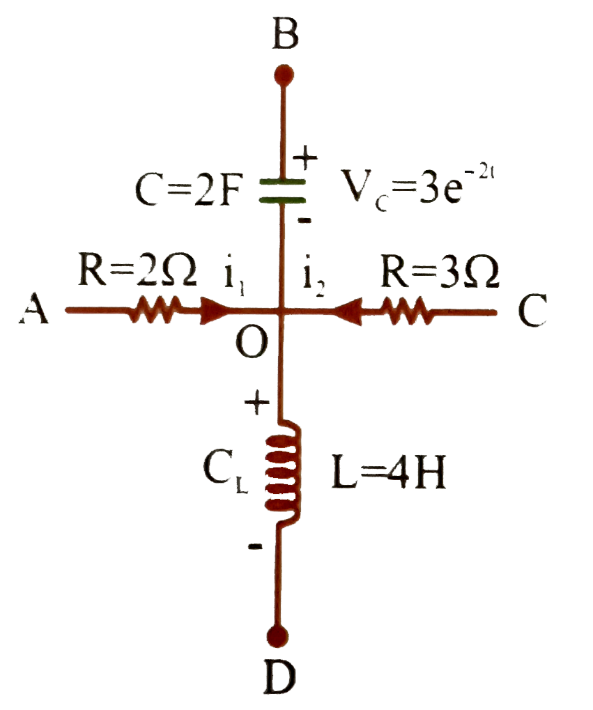
The potential difference across `AB (V_(AB))` is:
View SolutionIn figure `i_(1) = 10 e^(-2t) A, i_(2) = 4 A, v_(C ) = 3 e^(-2t) V`

The variation of potential difference acorss `A` and `C` with time can be represented as
View SolutionAn ac generator `G` with an adjustable frequency of oscillation is used in the circuit, as shown.
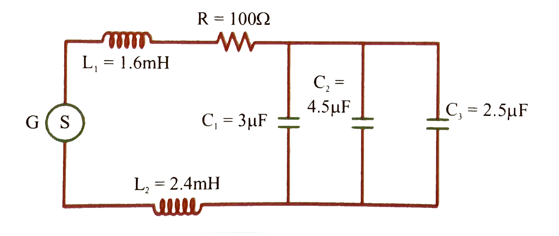
Current drawn from the ac souce will be maximum if its angular frequency is
View SolutionAn ac generator `G` with an adjustable frequency of oscillation is used in the circuit, as shown.
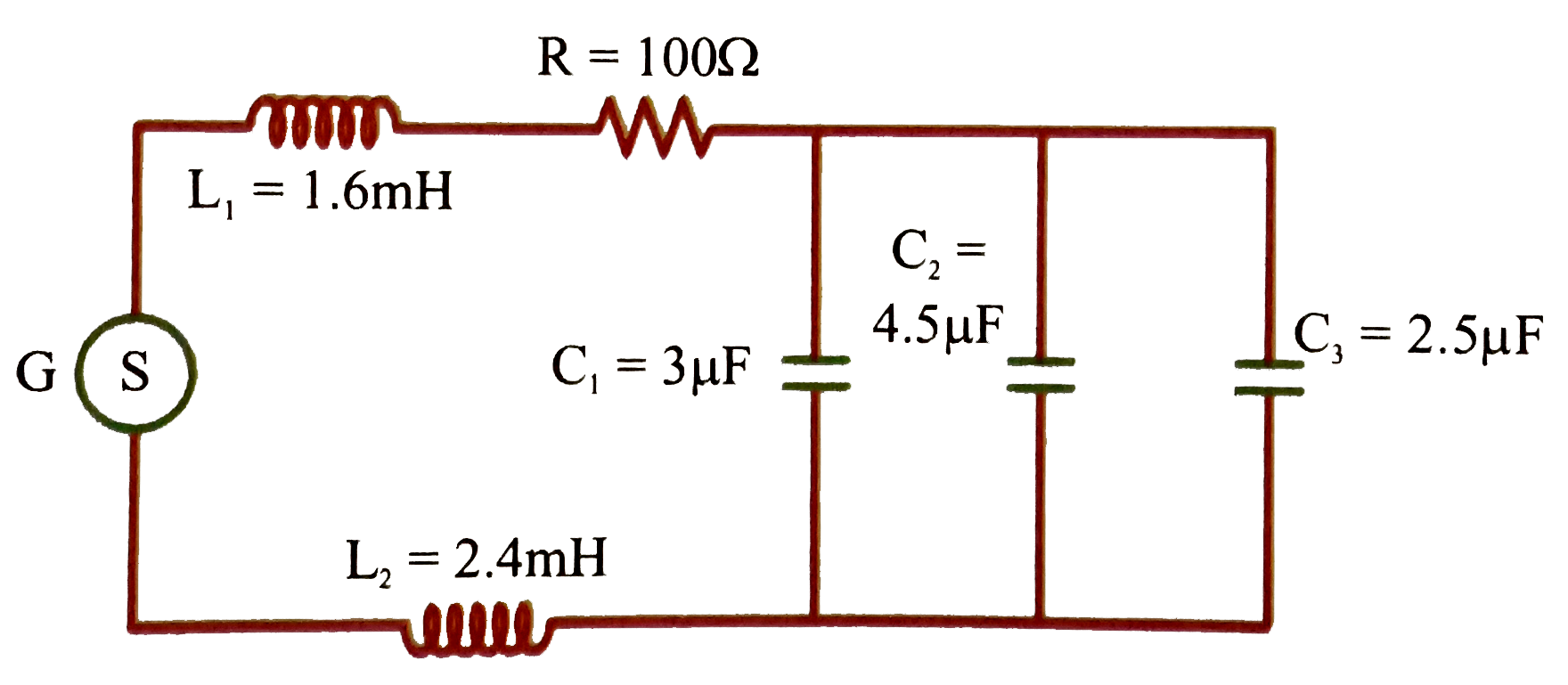
To increase resonant frequency of the circuit, some of the changes in the circuit are carried out. Which changes would certainly result in the increase in resonnatn frequency ?
View SolutionAn ac generator `G` with an adjustable frequency of oscillation is used in the circuit, as shown.
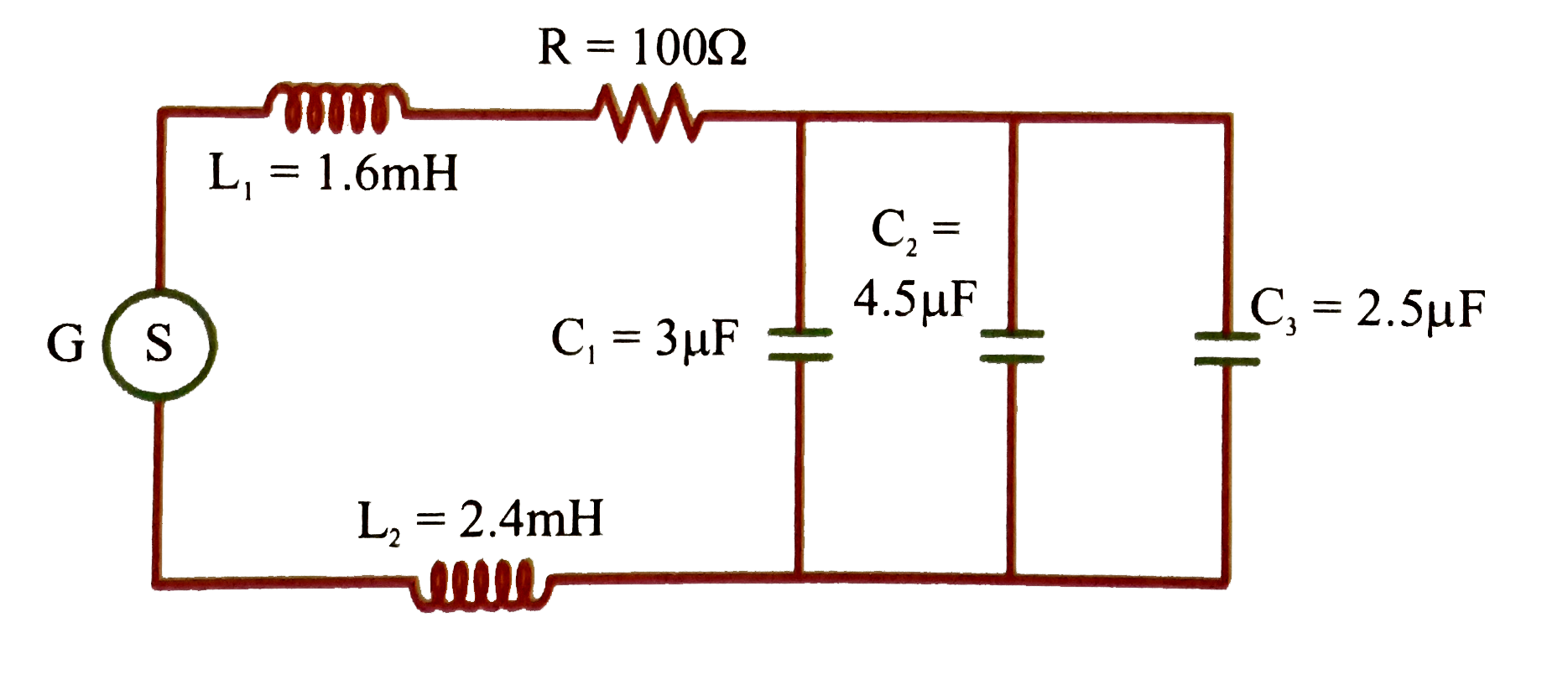
If the ac source `G` is `100 V` rating at resonant frequency of the circuit, then average power supplied by the source is
View SolutionAn ac generator `G` with an adjustable frequency of oscillation is used in the circuit, as shown.
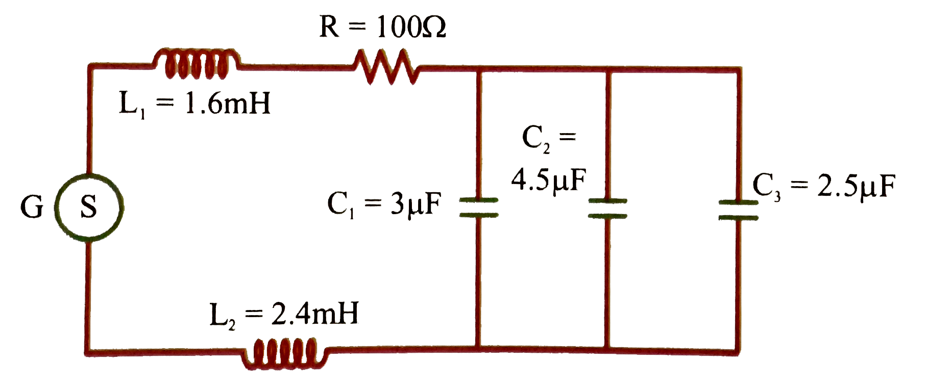
Average energy stored by the inductor `L_(2)` (source is at resonance frequency) is equal to
View SolutionAn ac generator `G` with an adjustable frequency of oscillation is used in the circuit, as shown.

If the ac source `G` is `100 V` rating at resonant frequency of the circuit, then average power supplied by the source is
View Solution
LEVEL - V questions and complete solutions for chapter ALTERNATING CURRENT of NARAYANA PHYSICS (HINGLISH) of Class 12