Complete Solutions to LEVEL - VI of chapter ALTERNATING CURRENT of Class 12 book with complete answers and questions
| Class 12 | PHYSICS |
| Chapter | ALTERNATING CURRENT |
| NARAYANA | LEVEL - VI |
| Number Of Questions | 100 |
| Academic Year | 2023-24 |
If a direct current of value `'a'` ampere is supermposed on an alternating current `I = b sin omega t` flowing through a wire, what is the effective value of the resulting current in the circuit?

View SolutionThe secondary coil of an ideal step down transformer is delivering 500 watt power at `12.5 A` current. If the ratio of turns in the primary to the secondary is `5 : 1` then the current flowing in the primary coil will be:
View SolutionIn a step-up transformer the turn's ratio is 10. If the frequency of the current in the primary coil is `50 Hz` then of the frequency of the current in the second ary coil will be
View SolutionAn alternating voltage of 200 volt, at 400 cycyles`//`sec in applied in a circuit containing an inductance of 0.01 henry in series with a resistanceof 22.8 ohms. The voltage across the inductance is
View SolutionIf the readings `V_(1)` and `V_(3)` are 10. volt each, then reading of `V_(2)` is:
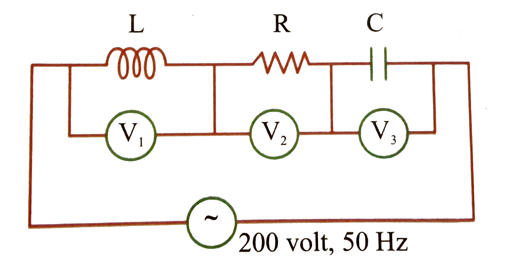
View SolutionIn the a.c. circuit shown in the figure. The supply voltage has a constant r.m.s value `V` but varialbe frequency `f`. Resonance frequency in hertz is
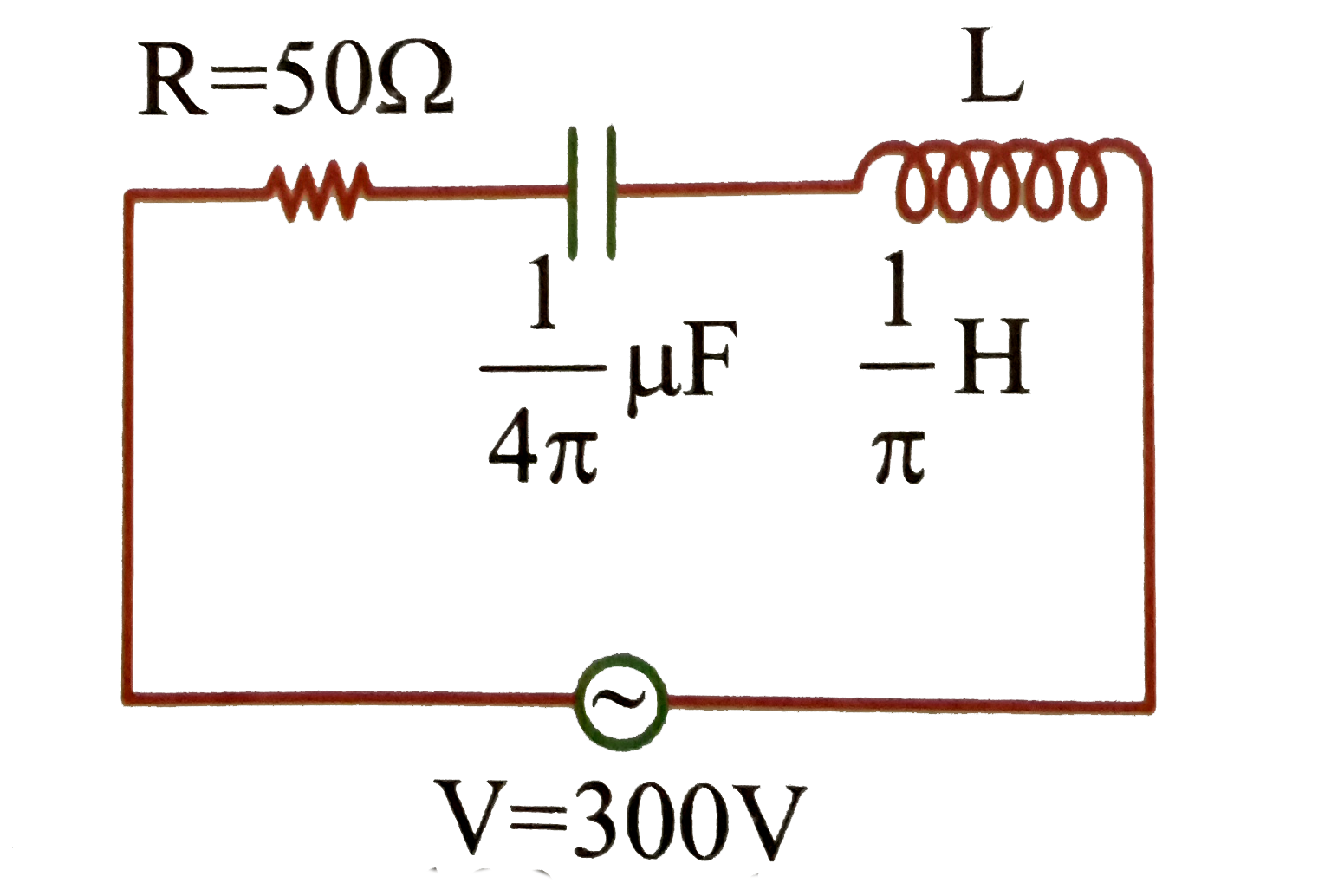
View SolutionIf the power factor is `1//2` in a series `RL` circuit with `R = 100 Omega`. If `AC` mains, `50 Hz` is used then `L` is
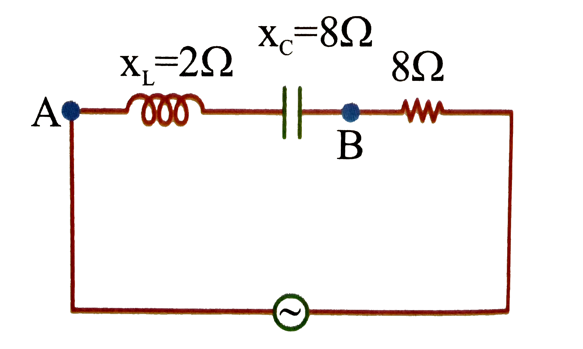
View SolutionAn inductor `(X_(L) = 2 Omega)` a capacitor `(X_(C ) = 8 Omega)` and a resistance `(8 Omega)` are connected in series with an ac source. The voltage output of `A.C` source is given by `v = 10 cos 100 pi t`. The instantaneous p.d. between `A` and `B` when is half of the voltage output from source will be:
View SolutionA resistor of resistance `100 Omega` is connected to an `AC` source `epsilon = (12 V) sin (250 pi s^(-1))t`. Find the energy dissipated as heat during `t = 0` to `t = 1.0 ms`.
View SolutionIn the given `AC`, circuit, which of the following in incorrect:
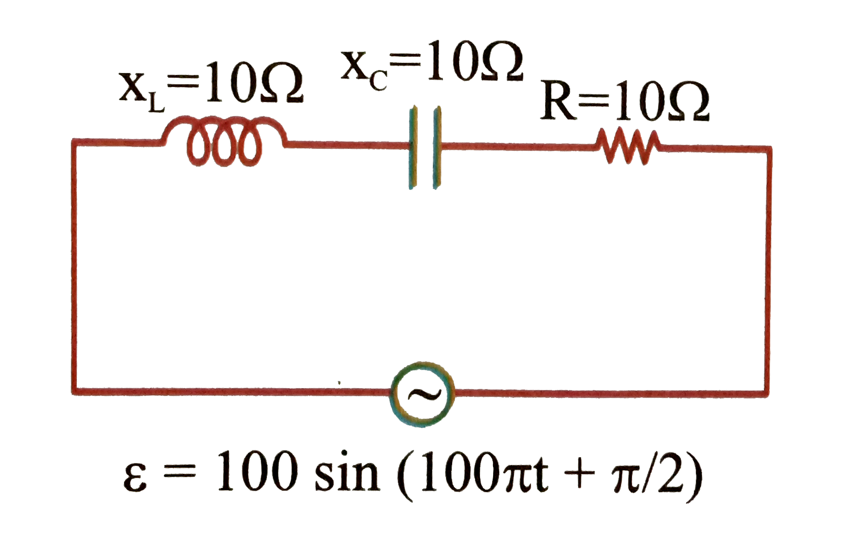
View SolutionIn the series circuit shown in the figure the voltmeter reading will be (all the meters are ideal).
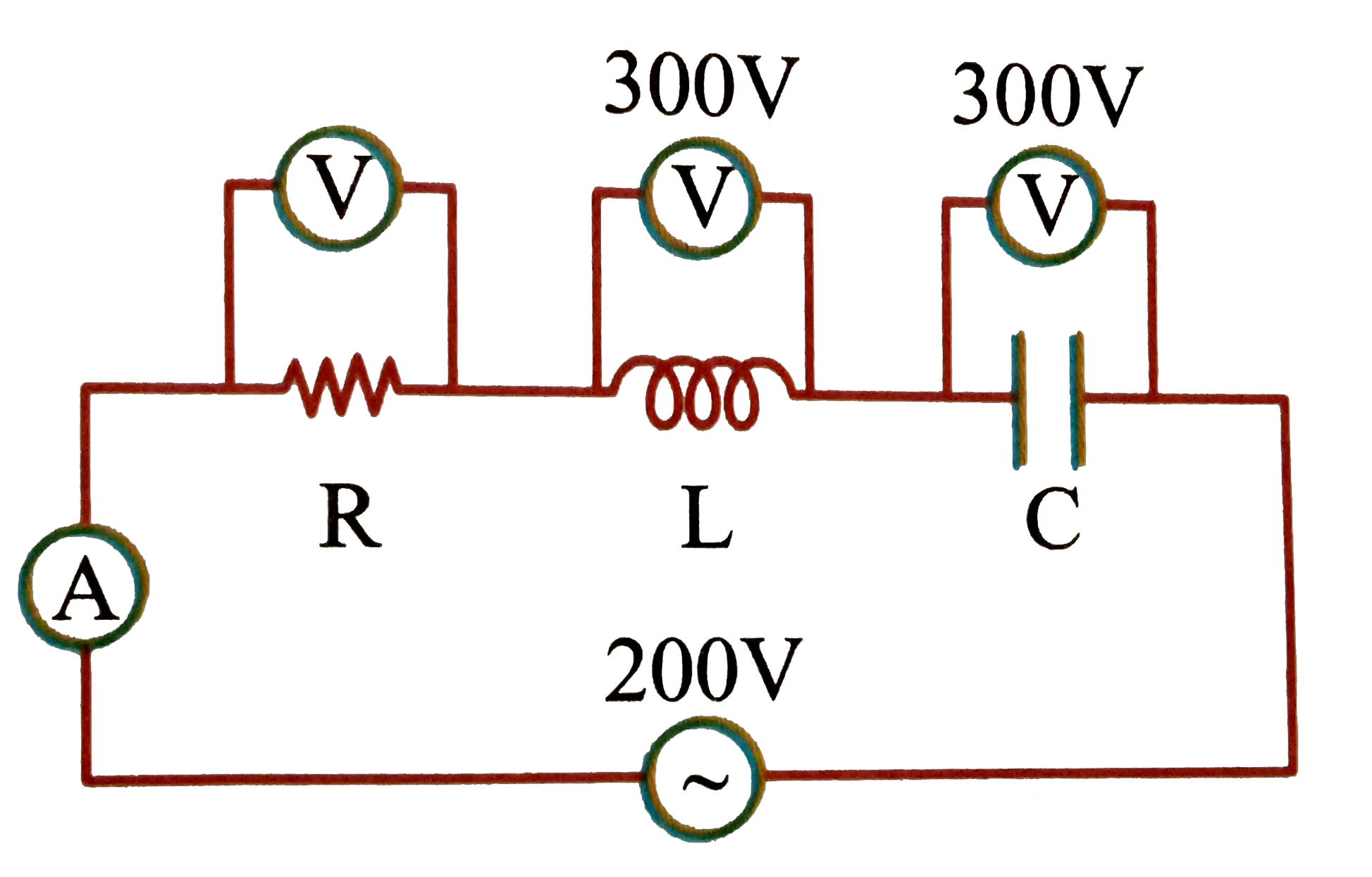
View SolutionIn the circuit shown in fig. `X_(C ) = 100 Omega,(X_L)=200 Omega and R=100 Omega`. The effective current through the source is
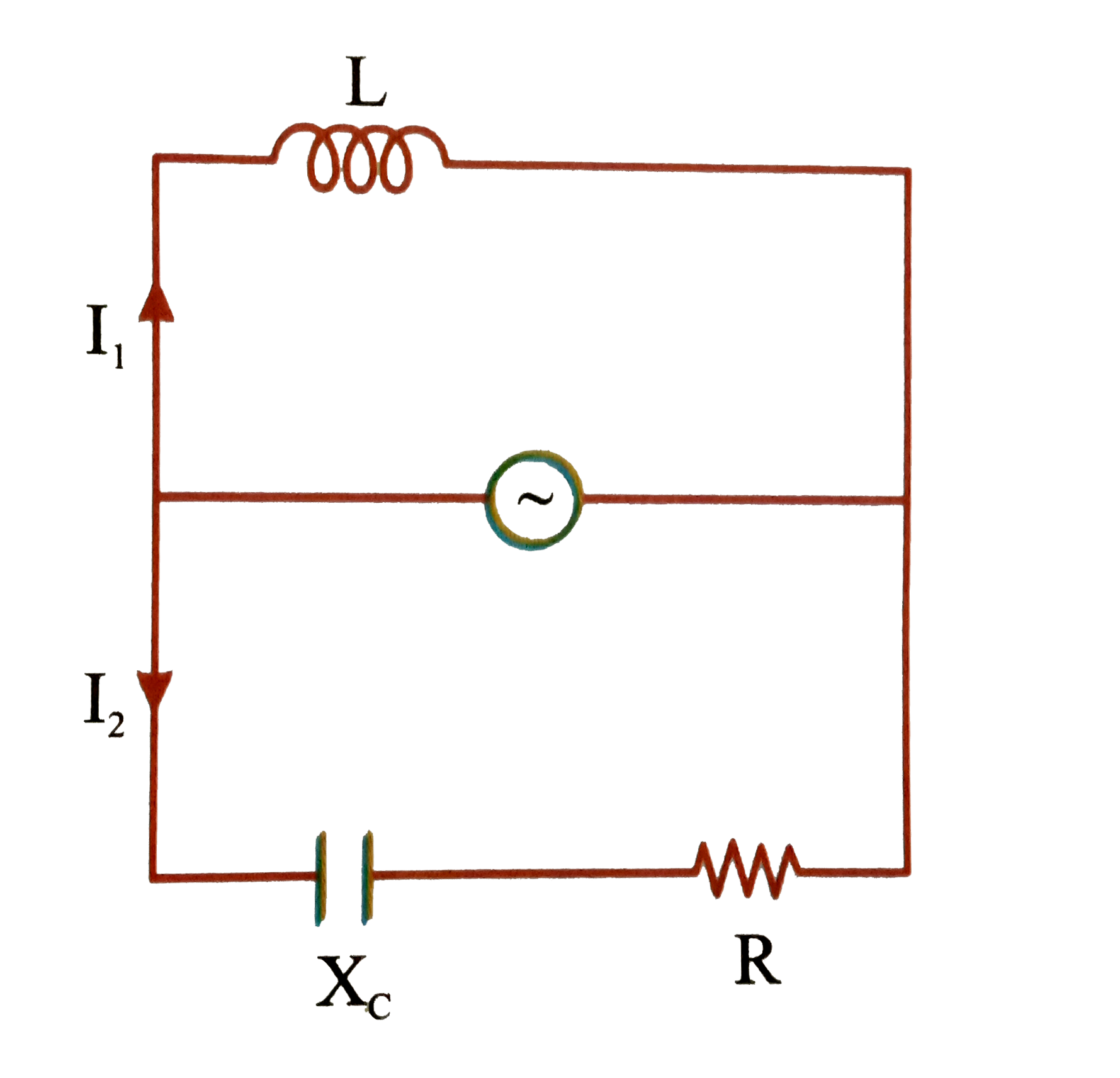
View SolutionIn the given circuit assuming inductor and source to be ideal, the phase differece between current `I_(1)` and `I_(2)` :
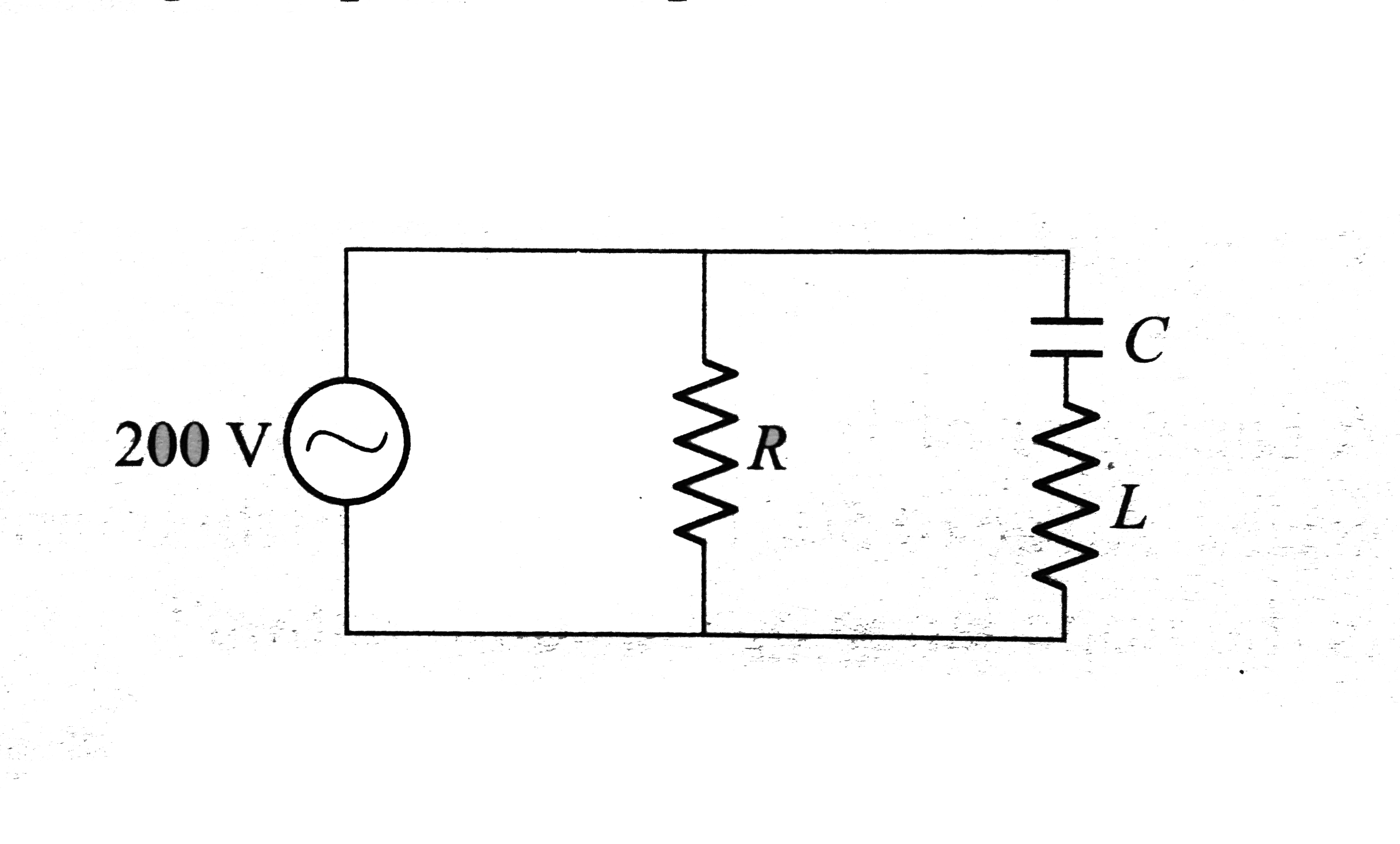
View SolutionIn the circuit current through source will be
[Given `(cos^(-1) (0.6) = 53^(@))]`
`V = 10 + 10 sqrt(2) sin (100 pi + 45^(@))`
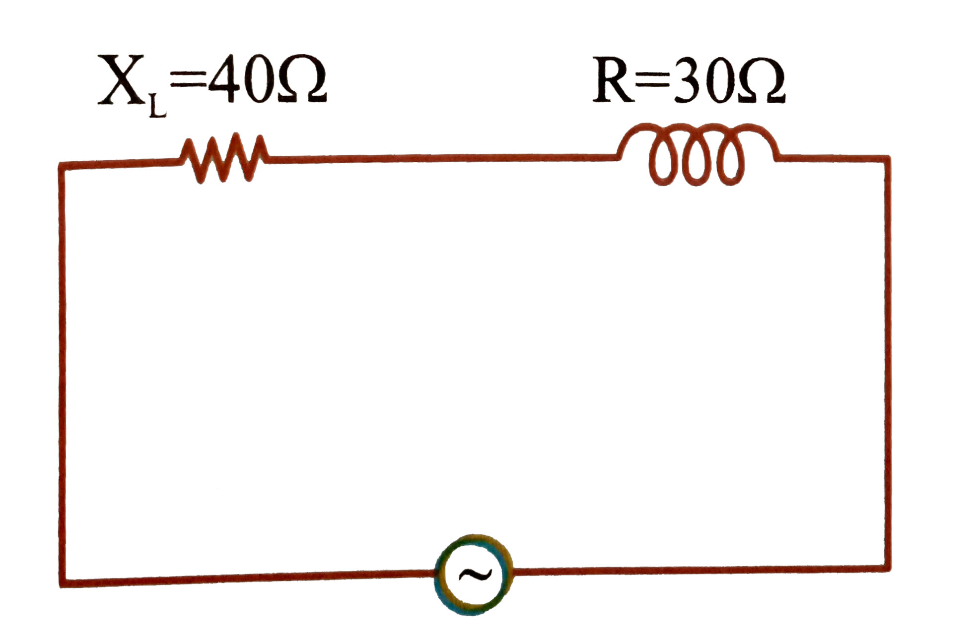
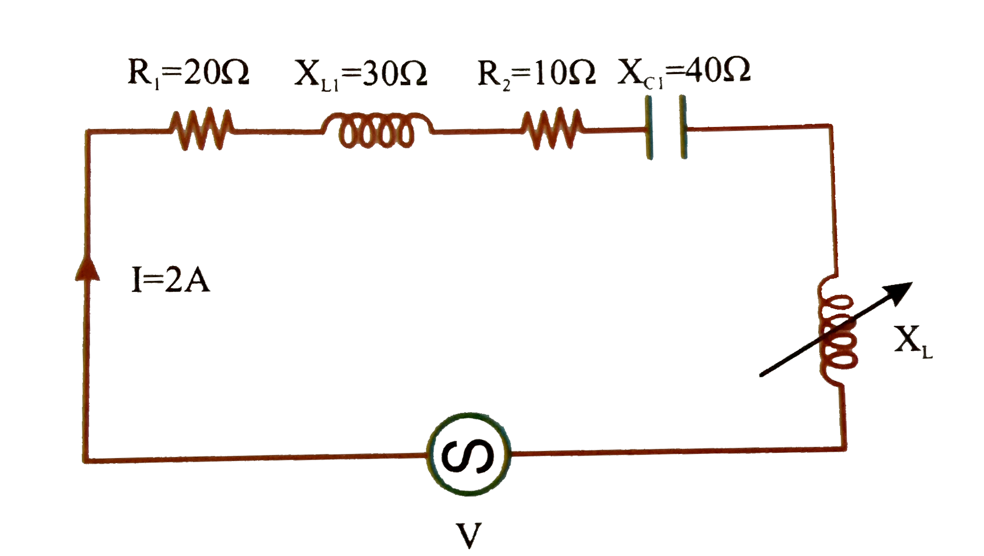
View SolutionIn figure below if `Z_(1) = Z_(C )` and reading of ammeter is `1A`. Find value of source voltage `V`.
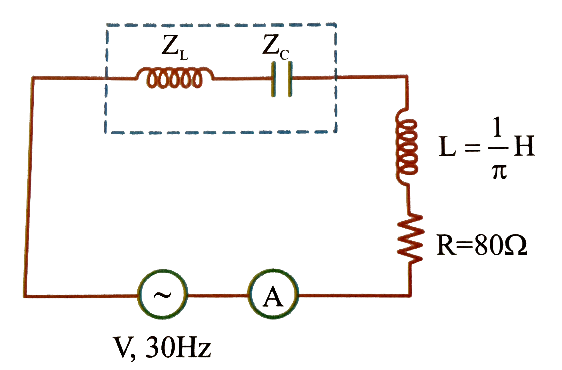
View SolutionAs shown in figure value of inductive reactance `X_(L)` will be (source voltage is 100 volt)
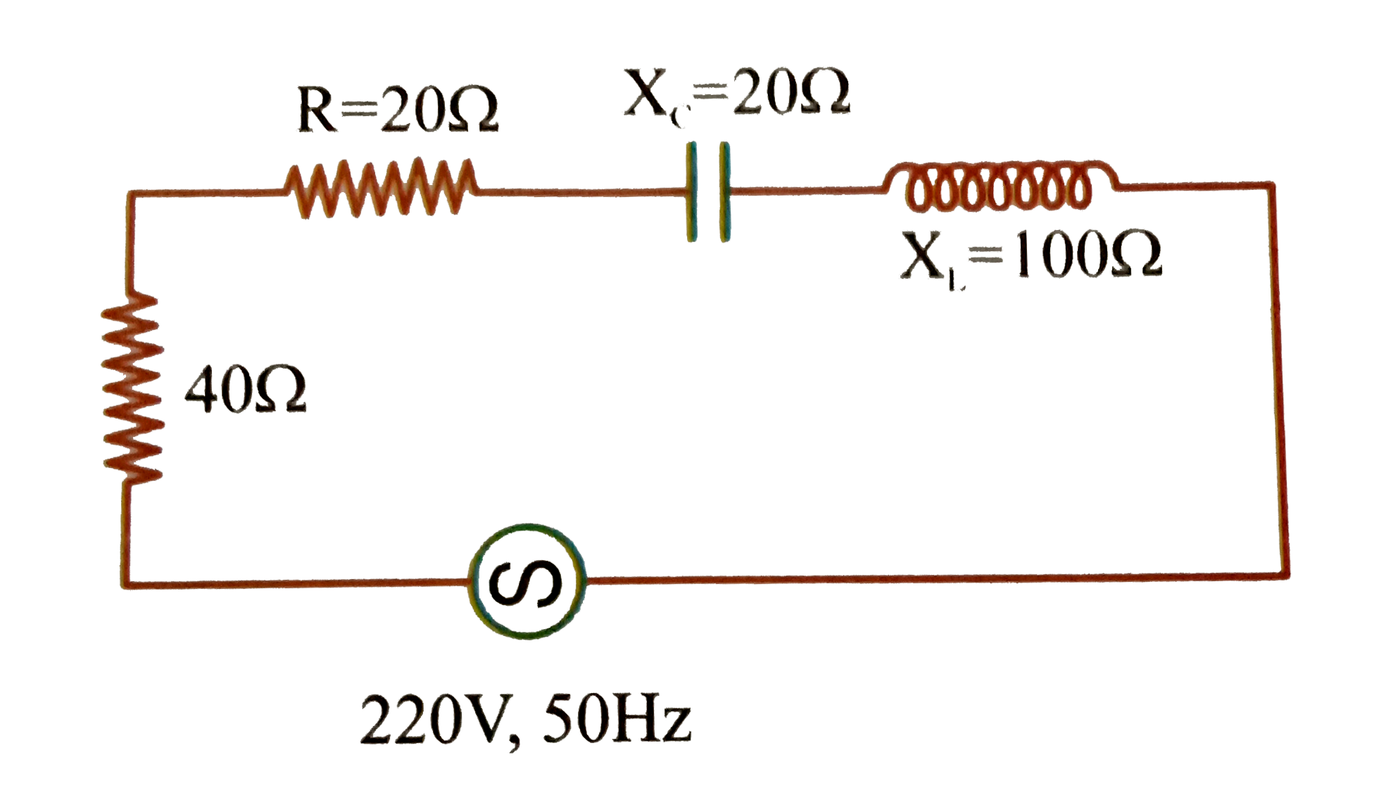
View SolutionThe power factor of the circuit shown in the figure is
View SolutionIn an `L-R-C` circuit the current is given by `i = I cos omega t`. The voltage amplitudes for the resistor. Inductor and capacitor are `V_(R ), V_(L)` and `V_(C )` respectively.
(a) The instantaneous power into the resistor is `P_(R ) = V_(R ) I cos^(2) omega t`.
(b) The instantaneous into the inductor is `P_(L) = - V_(L) I sin omega t cos omega t`
(c ) The instantaneous power into the capacitor is `P_(c ) = V_(c ) I sin omega t cos omega t`.
(d) `p_(R ) + p_(L) + P_(c )` equals total power `p` supplied by the source at each instant of time.
View SolutionThe diagram shows a capacitor `C` and a resistor `R` connected in series to an `AC` source. `V_(1)` and `V_(2)` are voltmeters and `A` is ammeter
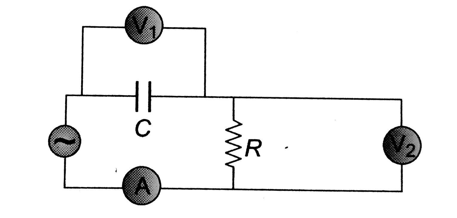
Now, consider the following statemensts :
(I) Reading in `A` and `V_(2)` are always in phase.
(II) Reading in `V_(1)` is ahead in phase with reading in `V_(2)`,
(III) Reading in `A` and `V_(1)` are always in phase. Which of these statements are/is correct
View SolutionTwo impedances `Z_1` and `Z_2` when connected separately across a `230 V, 50 Hz` supply consume `100 W` and `60 W` at power factor of `0.5` lagging and `0.6` leading respectively. If these impedances are now connected in series across the same supply, find
(a) total power absorbed and overall power factor
(b) the value of reactance to be added in series so as to raise the overall power factor to unity.
View SolutionIn the `LCR` circuit shown in figure
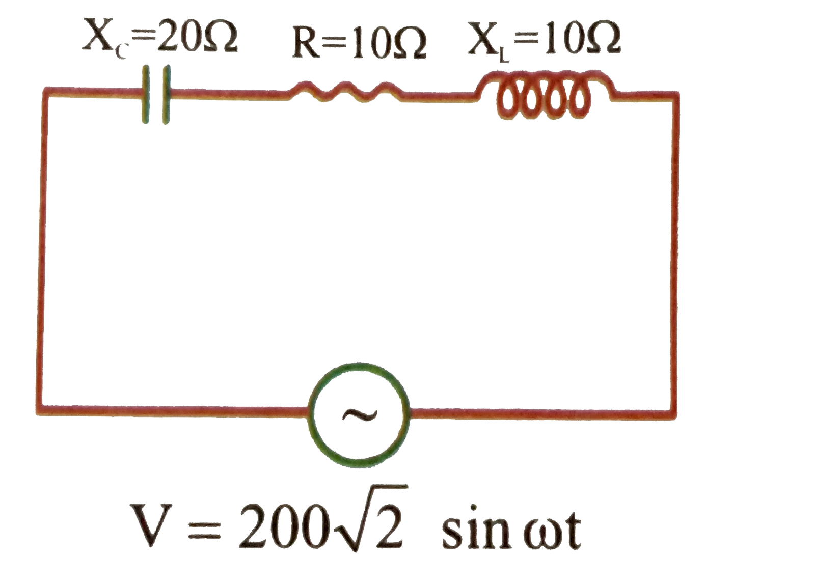
(a) current will lead the voltage
(2) rms value of current in `20 A`
(3) power factor of the circuit is `(1)/(sqrt(2))`
(4) voltage drop across resistance is `100 V`
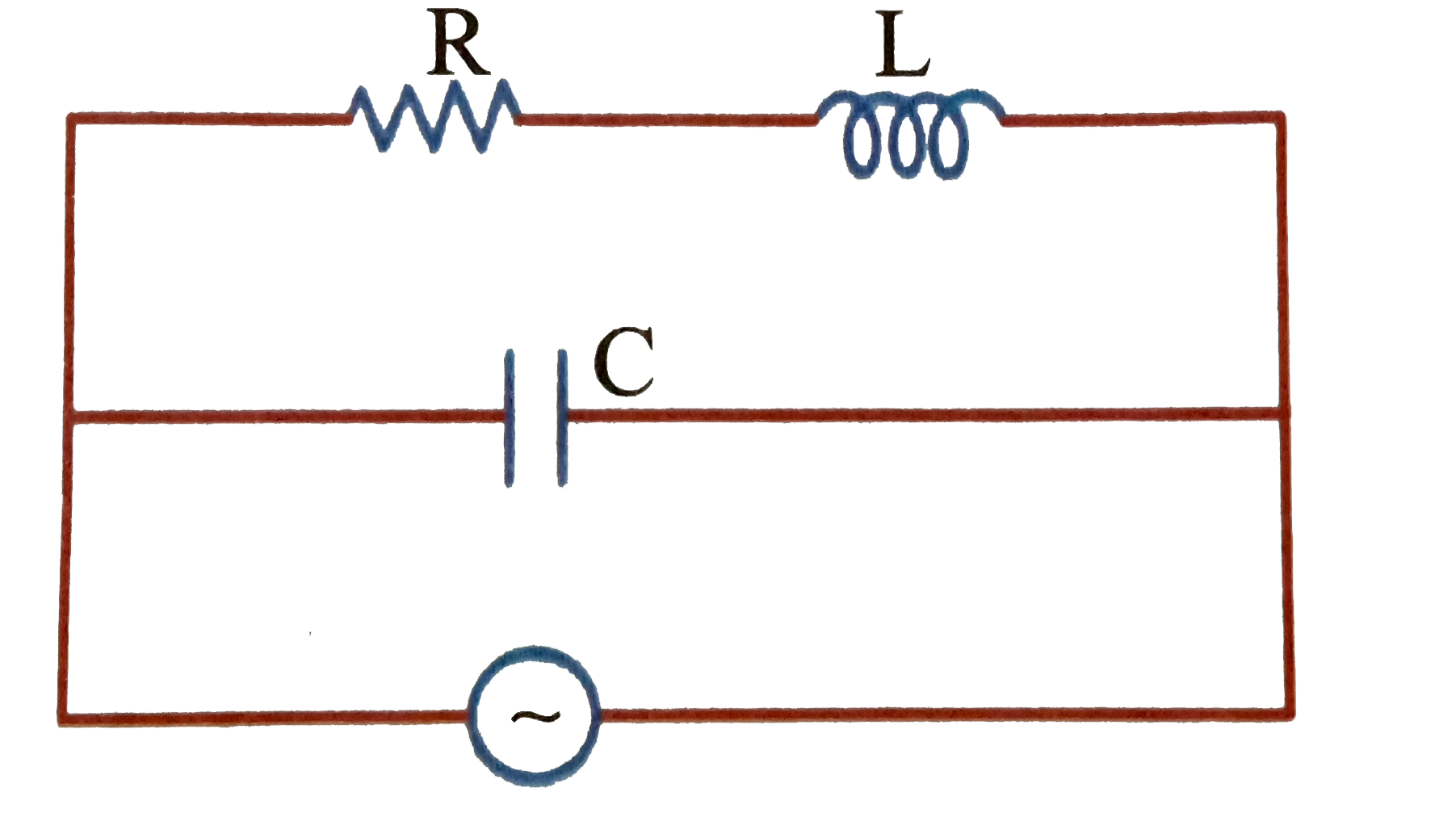
View SolutionThe `A.C` circuit shown in figure. Find the frequency `(w_(0))` of the `AC` voltage source so that current through the source will be in same phase with the voltage of source.
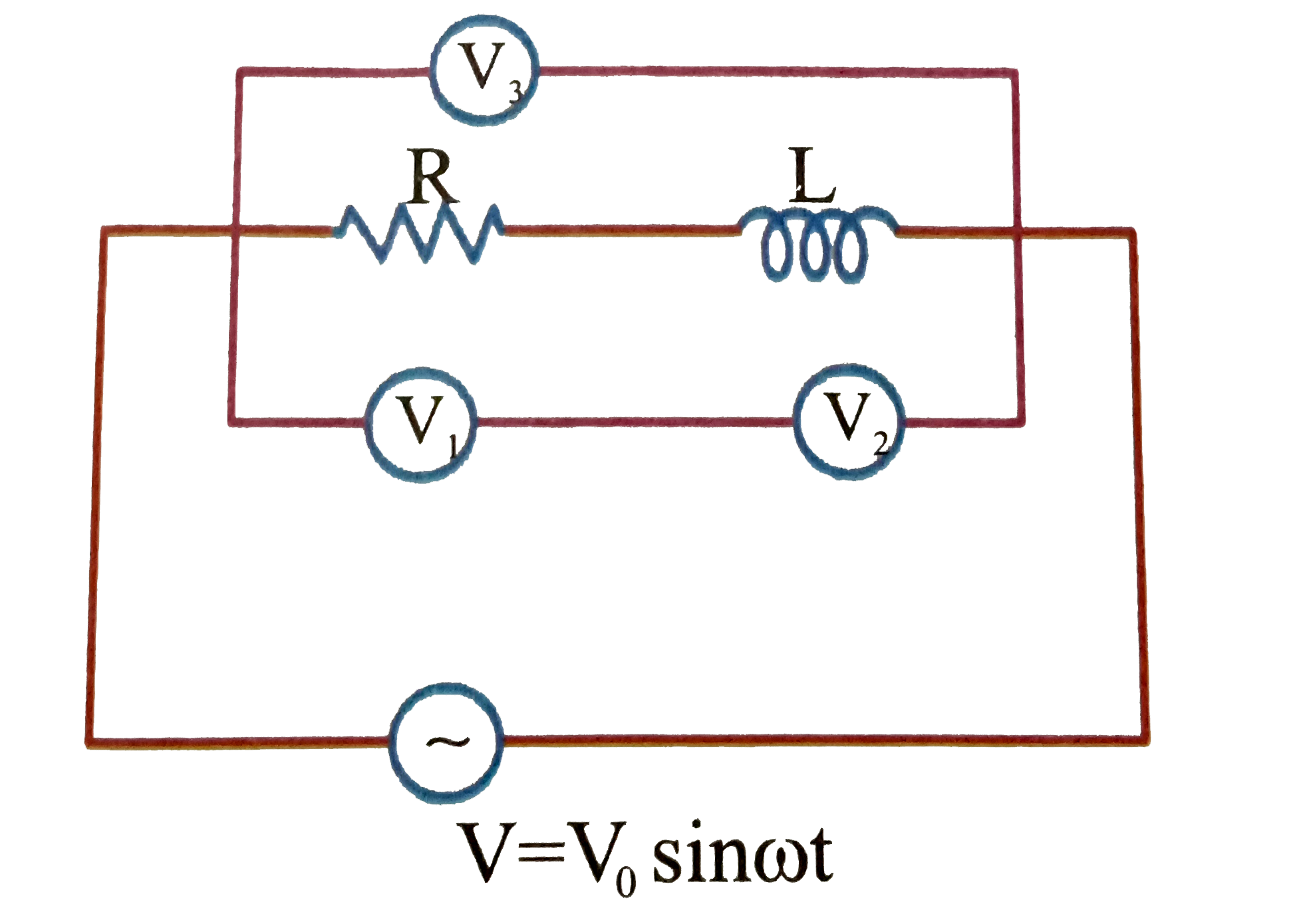
View SolutionA resistance & ideal inductor is connected in the `A.C` circuit. Here `V_(1), V_(2) & V_(3)` are the reading of three hotwire ideal voltmeter
View SolutionIn an AC series circuit, the instanctaneous current is zero when the instantaneous voltage is xamimum. Connected to the source may be a
View SolutionWhich statement(s) is False for the series resonant condition
View SolutionAn alternating EMF of frequency `(1)/(2pi sqrt(LC))` is applied to a series LCR circuit. For this frequency of the applied EMF,
View SolutionAn `LC` source rated `100 V` (rms) supplies a current of `10 A` (rms) to a circuit. The average power delivered by the source
View SolutionIn a `L-R` circuit, the value of `L` is `(0.4/(pi))` henry and the value of `R` is `30` ohm. If in the circuit, an alternating e.m.f of `200` vol at `50` cycles per sec is connected, the impendence of the circuit will be
View SolutionA circuit has three elements, a resistance fo `11 Omega`, a coil of inductaive reactance `120 Omega` and a capacitve reactance of `120 Omega` in series and connected to an `A.C` source of `110 V, 60 Hz`. Which of the three elements have minimum potential difference?
View SolutionAn inductor `20 xx 10^(-3)` henry, a capacitor `100 mu F` and a resistor `50 Omega` are connected in series across a source of emf `V = 10 sin 314 t`.
(a) The energy dissipated in the circuit in 20 minutues is `951 J`.
(b) If resistance is removed from the circuit and the value of inductance is doubled, then the varation of current with time in the new circuit is `0.52 cos (314 t)`
View SolutionIn a series `LCR` circuit
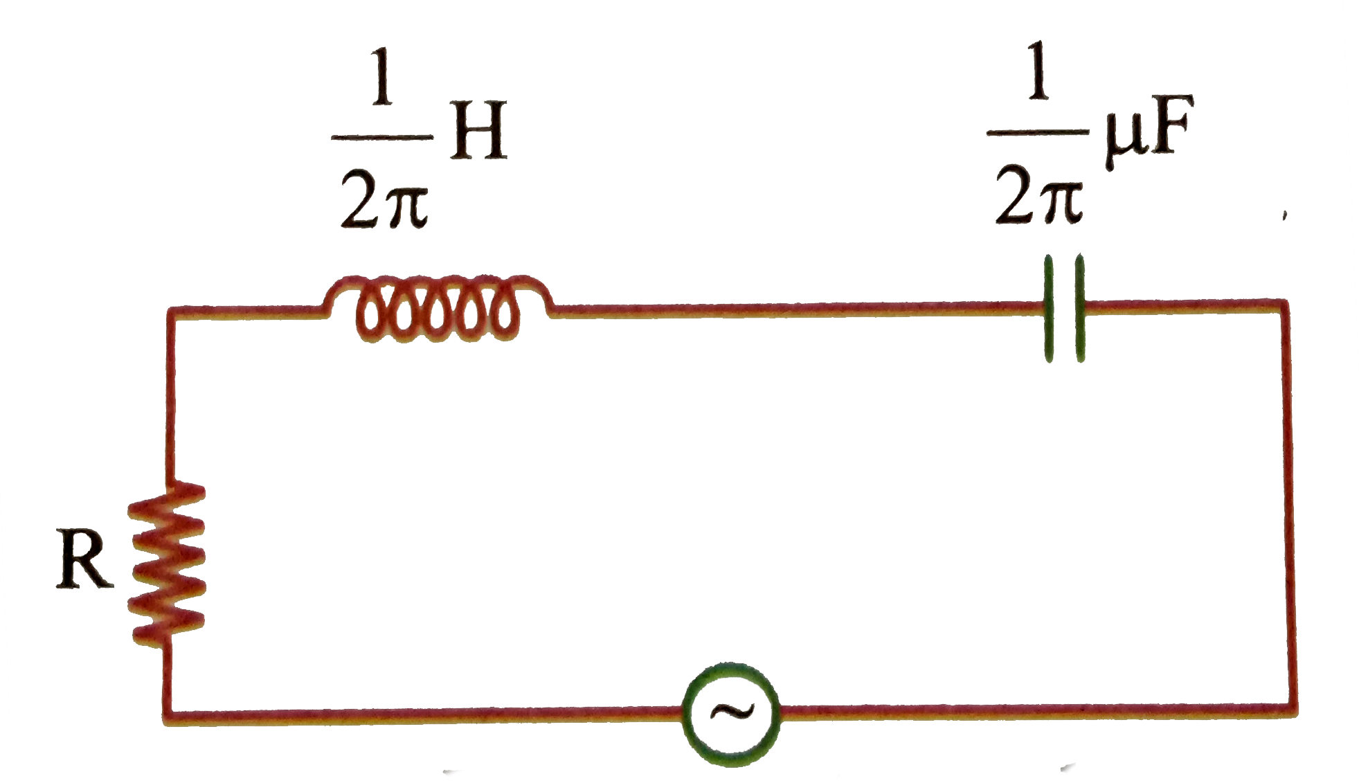
View SolutionIn the figure shown `R = 100 Omega L = (2)/(pi) H` and `C = (8)/(pi) mu F` are connected in series with a.c source of 200 volt and frequency `'f'`. `V_(1)` and `V_(2)` are two hot-wire voltmeters. If the readings of `V_(1)` and `V_(2)` are same then:
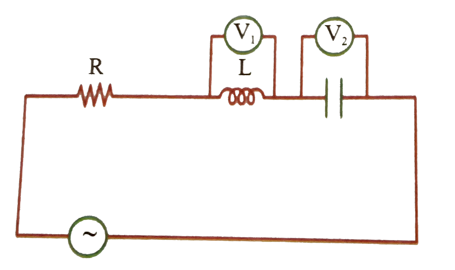
View SolutionChoose correct statement if capcitance increases from zero `(0)` to inifinity `oo`
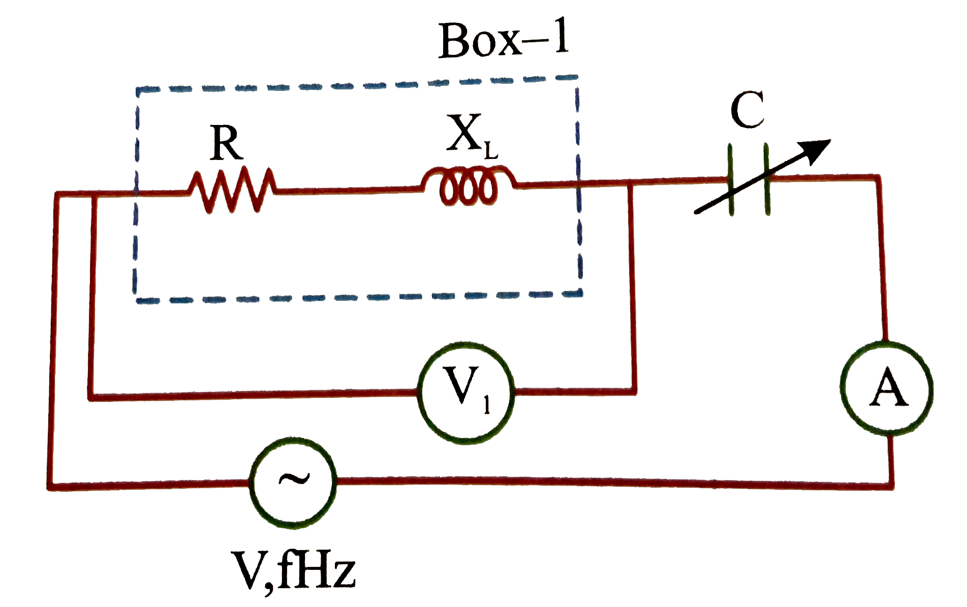
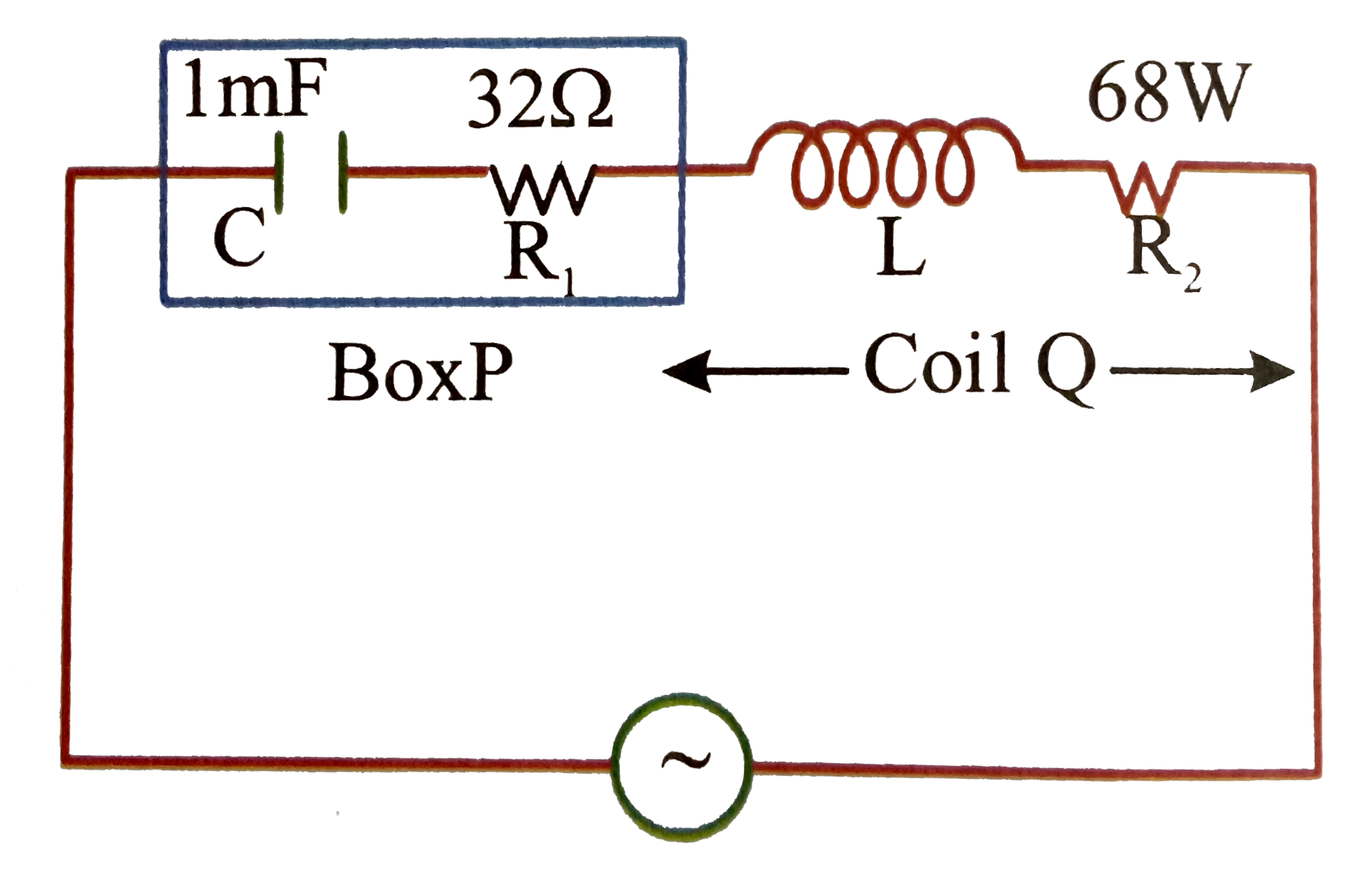
View SolutionA box `P` and a coil `Q` are connected in series with an `AC` source of variable frequency. The emf of the source is constant at `10 V`. Box `P` contains a capacitance of `1 mu F` in series with a resistance of `32 Omega`. Coil `Q` has a self-inductance 4.9 mH and a resistance of `68 Omega` in series. The frequency is adjusted to that the maximum current flows in `P` and `Q`. At this frequency
(a) The impedance of `P` is `77 Omega`
(b) The impedance of `Q` is `85 Omega`
(c ) Voltage across `P` is `7.7 V`
(d) Voltage across `Q` is `9.7 V`
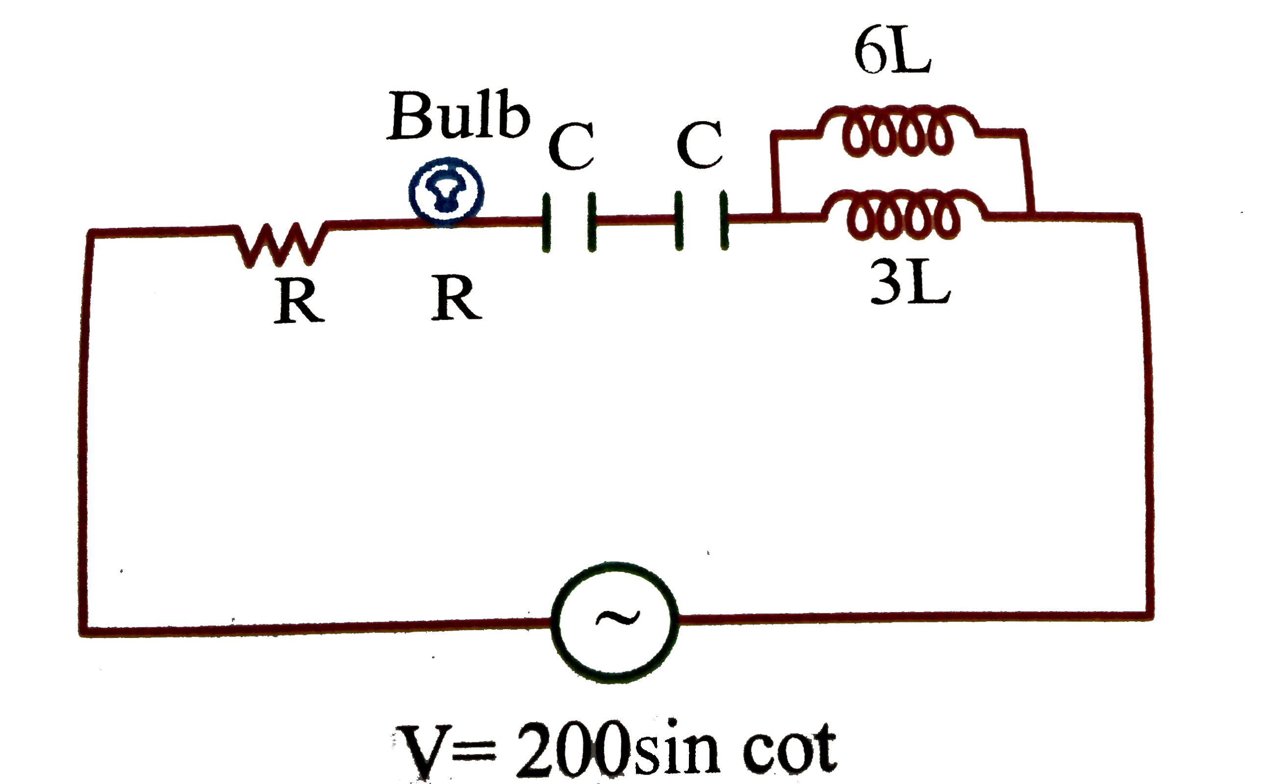
View SolutionA series `LCR` circuit containing a resistance of `120 Omega` has angular resonance frequency `4 xx 10^(5) "rads"^(-1)`. At resonance the voltages across resistance and inductance are `60 V` and `40 V` respectively.
(a) The value of `L` and `C` are `0.2` mH, `1/32 muF`
(b) If angular frequency is changed to `8xx10^(5) "rad"//s`, the current lags the voltage by `45^(@)`
(c) If angular frequency is charged to `6xx10^(5) "rad"//s`, the current lags the voltage by `45^(@)`
View SolutionA current of `4A` flows in a coil when connected to a `12V DC` source. If the same coil is connected to a `12V, 50 rad//s AC` source, a current of `2.4A` flows in the circuit. Determine the inductance of the coil. Also, find the power developed in the circuit if a`2500muF` capacitor is connected in series with the coil.
View SolutionIn the given series `R-L-C` circuit, `R = 100 Omega, L = 10^(-3) H, C= 0.1 mu F, V_(0) = 200 V`
(a) The resonant frequency is `15924 Hz`
(b) The current at resosnance is `1A`
(c ) The power dissipated in the circuitd at resonance is `100 W`
View SolutionAn alternating emf of frequency `f = 50 Hz` peak voltage `V_(0) = 21` volt is applied to a series circuit of resistance `R = 20` ohm, an inductance `L = 100 mH` and a capacitor of `C = 30 mu F`.
(a) The maximum currentd is `3 A`
The phase difference between current and applied voltage is `75^(@)`
(c ) The current `i` as a function of time `'t'` is `i = 3 sin (314 t + 75^(@))`
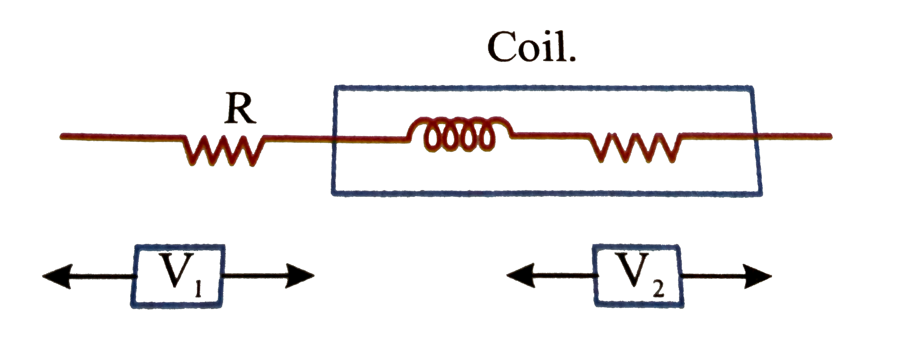
View SolutionA resistor `R` is connected in series with a coil. The system is subjected to an `AC` supply of peak voltage `V_(0)`. If the peak voltages dropped across the resistor `R` and the coil are `V_(1)` and `V_(2)` respectively
(a) The powerr dissipated in the coil is
`(V_(0)^(2) - V_(1)^(2) - V_(2)^(2))/(2R)`
The power dissipated in the circuit is
`(V_(0)^(2) + V_(1)^(2) - V_(2)^(2))/(2R)`
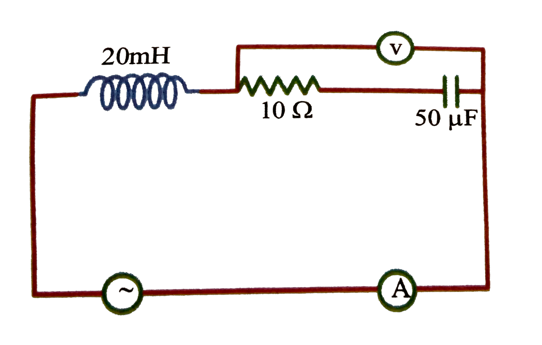
View SolutionFor the `AC` circuit shown, the reading of ammeter and voltmeter are `5A` and `50 sqrt(5)` volts respectively, then
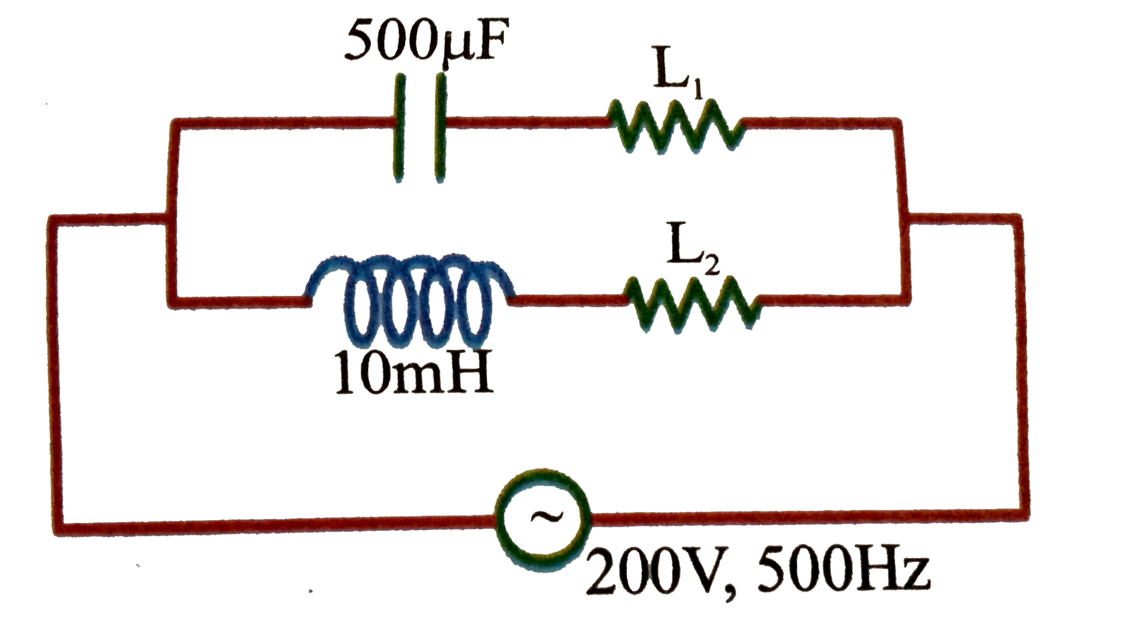
View SolutionIn the circuit shown in Fig. If both the lamps `L_(1)` and `L_(2)` are identical.
View SolutionA series LCR circuit with `L= 0.12H, C=480 nF,` and `R=23 Omega` is connected to a `230V` variable frequency supply.
(a) What is the source frequency for which current amplitude is maximum? Find this maximum value.
(b) What is the source frequency for which average power absorbed by the circuit is maximum? Obtain the value of maximum power.
(c ) For which frequencies of the source is the power transferred to the circuit half the power at resonant frequency?
(d) What is the Q-factor of the circuit?
View SolutionAn ac source of angular frequency `omega` is fed across a resistor R and a capacitor C in series. The current registered is I. If now the frequency of source is changed to `omega//3` (but maintaining the same voltage), the current in the circuit is found to be halved. Calculate the ratio of the reactance to resistance at the original frequency `omega`.
View SolutionA circuit has a coil of resistance 60 ohm and inductance 3 henry. It is connected in series with a capacitor of `4 mu F` and `A.C` supply voltage of `200 V` and 50 `"cycle"//"sec"`
View SolutionA circuit consists of a noniductive resistor of `50 Omega`, a coil of inductance `0.3 H` and resistance `2 Omega`, and a capacitor of `40 mu F` in series and is supplied with 200 volt rms at 50 cycles `//` sec. Then
View SolutionA coil of resistance `300 Omega` and inductance 1.0 henry is connected across an voltages source of frequency `300//2pi Hz`. The phase difference between the voltage and current in the circuit is
View SolutionA circuit draws a power of 550 watt from a source of 220 volt, `50 Hz`. The power factor of the circuit is 0.8 and the current lags in phase behind the potential difference. To make the power factor of the circuit as 1.0, The capacitance should be connected in series with it is
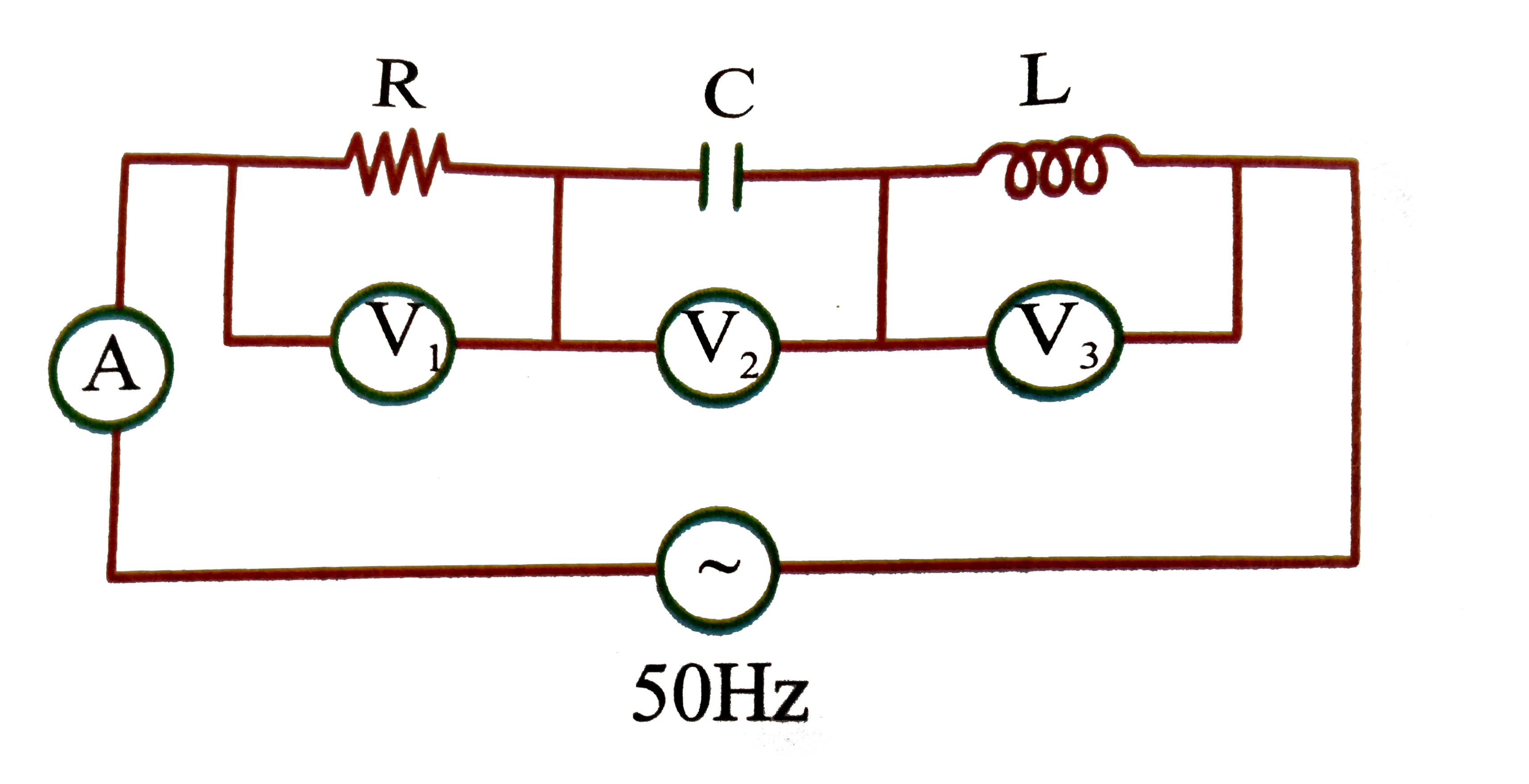
View SolutionIn the figure shown `V_(1),V_(2),V_(3)` are `AC` voltmeters and `A` is `AC` ammeter. The readings of `V_(1), V_(2), V_(3)` and `10 V, 20 V, 20 V, 2A` respectively. If the inductor is short circuited, then
View SolutionIn a series `LCR` circuit with an `ac` source of `50 V,R=300 Omega`,frequency `v=50/piHz`.The average electric field energy, stored in the capacitor and average magnetic energy stored in the coil are `25 mJ` and `5 mJ` respectively.The `RMS` current in the circuit is `0.10 A`.Then find
View SolutionAn `L-C-R` series circuit with `100Omega` resistance is connected to an `AC` source of `200V` and angular frequency `300rad//s`. When only the capacitance is removed, the current lags behind the voltage by `60^@`. When only the inductance is removed the current leads the voltage by `60^@`. Calculate the current and the power dissipated in the `L-C-R` circuit
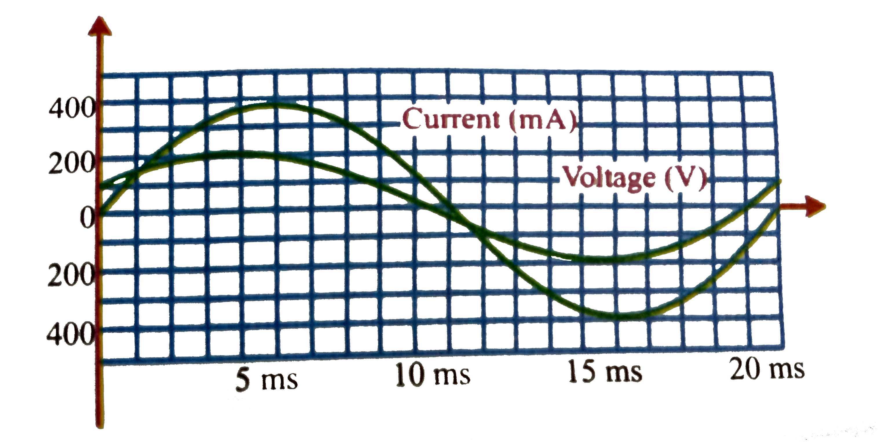
View SolutionThe given graph shows variation with time in the source voltage and steady state current drawn by a series `RLC` circuit. Given curve through origin is the current variation.
Which of the following statements `"is"//"are"` correct ?
View SolutionA `100 Omega` resistance is connected in series with a `4 H` inductor. The voltage across the resistor is, `V_(R ) = (2.0 V) sin (10^(3) t)`.
Find the expression of circuit current
View SolutionA `100 Omega` resistance is connected in series with a `4 H` inductor. The voltage across the resistor is, `V_(R ) = (2.0 V) sin (10^(3) t)`.
Find the inductive reactance
View SolutionA `100 Omega` resistance is connected in series with a `4 H` inductor. The voltage across the resistor is, `V_(R ) = (2.0 V) sin (10^(3) t)`.
Find amplitude of the voltage across the inductor.
View SolutionIf various elements, i.e., resistance capacitance and inductance which are in series and having values `1000 Omega, 1 mu F` and `2.0 H` respectively. Given emf as, `V = 100 sqrt(2) sin 1000 t` volts
Voltage across the resistor is
View SolutionIf various elements, i.e., resistance capacitance and inductance which are in series and having values `1000 Omega, 1 mu F` and `2.0 H` respectively. Given emf as, `V = 100 sqrt(2) sin 1000 t` volts
voltage across the inductor is
View SolutionIf various elements, i.e., resistance capacitance and inductance which are in series and having values `1000 Omega, 1 mu F` and `2.0 H` respectively. Given emf as, `V = 100 sqrt(2) sin 1000 t` volts
voltages across the capacitor is
View SolutionOne application of `L-R-C` series circuit is in high pass or low pass filter, which out either the low or high frequency components of a signal. A has pass filter is shown in figure where the output voltage is taken across the `L-R` where `L-R` combination represents and inductive coil that also has resistance due to the large length of the wire in the coil.
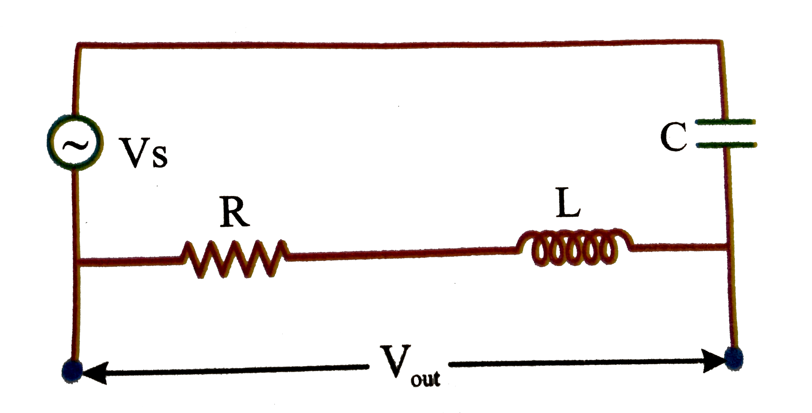
Find the ratio `V_("out") //V_(s)` as a function of the angular frequency `omega` of the source
View SolutionOne application of `L-R-C` series circuit is in high pass or low pass filter, which out either the low or high frequency components of a signal. A has pass filter is shown in figure where the output voltage is taken across the `L-R` where `L-R` combination represents and inductive coil that also has resistance due to the large length of the wire in the coil.
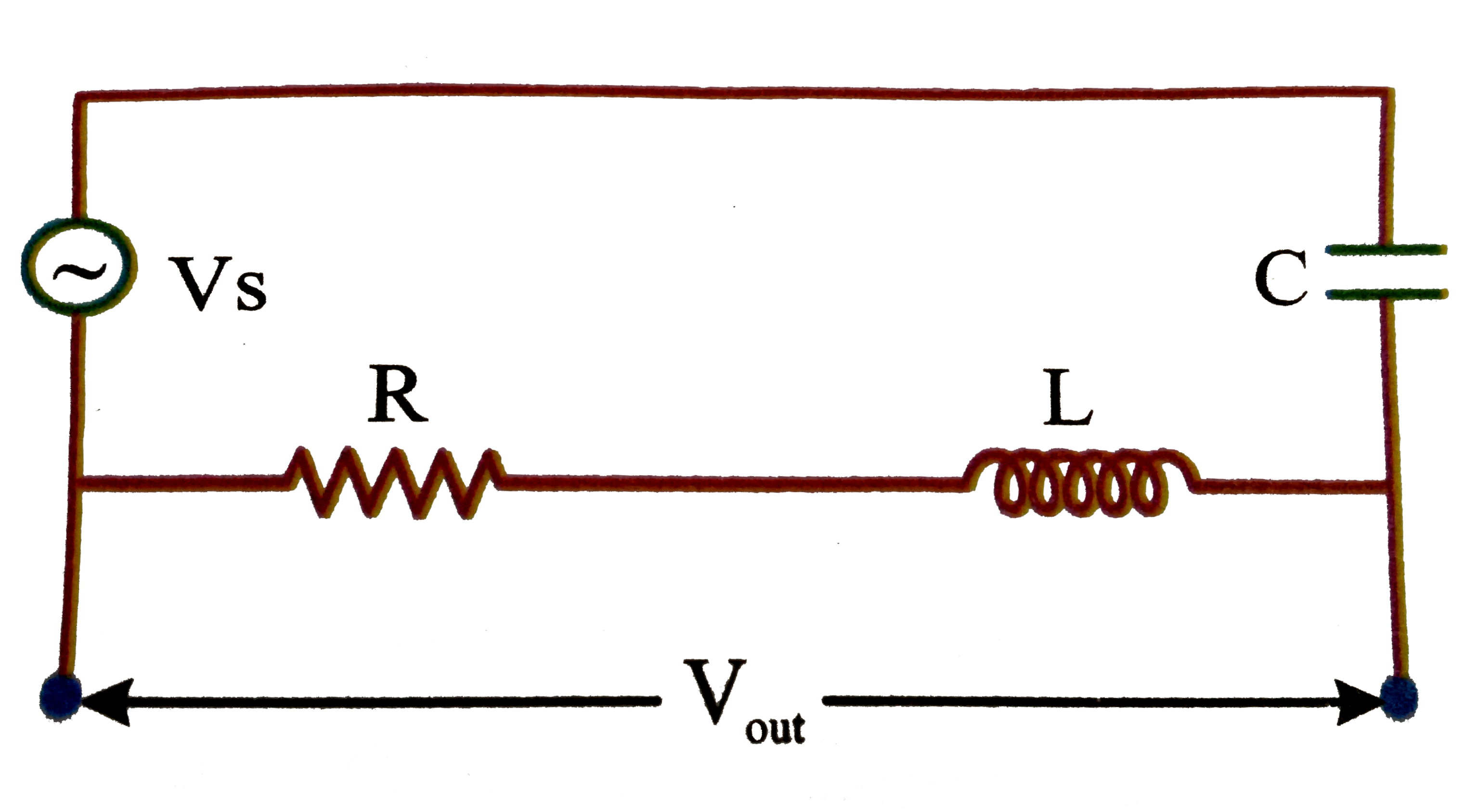
which of the following statementds is correct when `omega` is samll in the case of `V_("out")//V_(s)`
View SolutionOne application of `L-R-C` series circuit is in high pass or low pass filter, which out either the low or high frequency components of a signal. A has pass filter is shown in figure where the output voltage is taken across the `L-R` where `L-R` combination represents and inductive coil that also has resistance due to the large length of the wire in the coil.
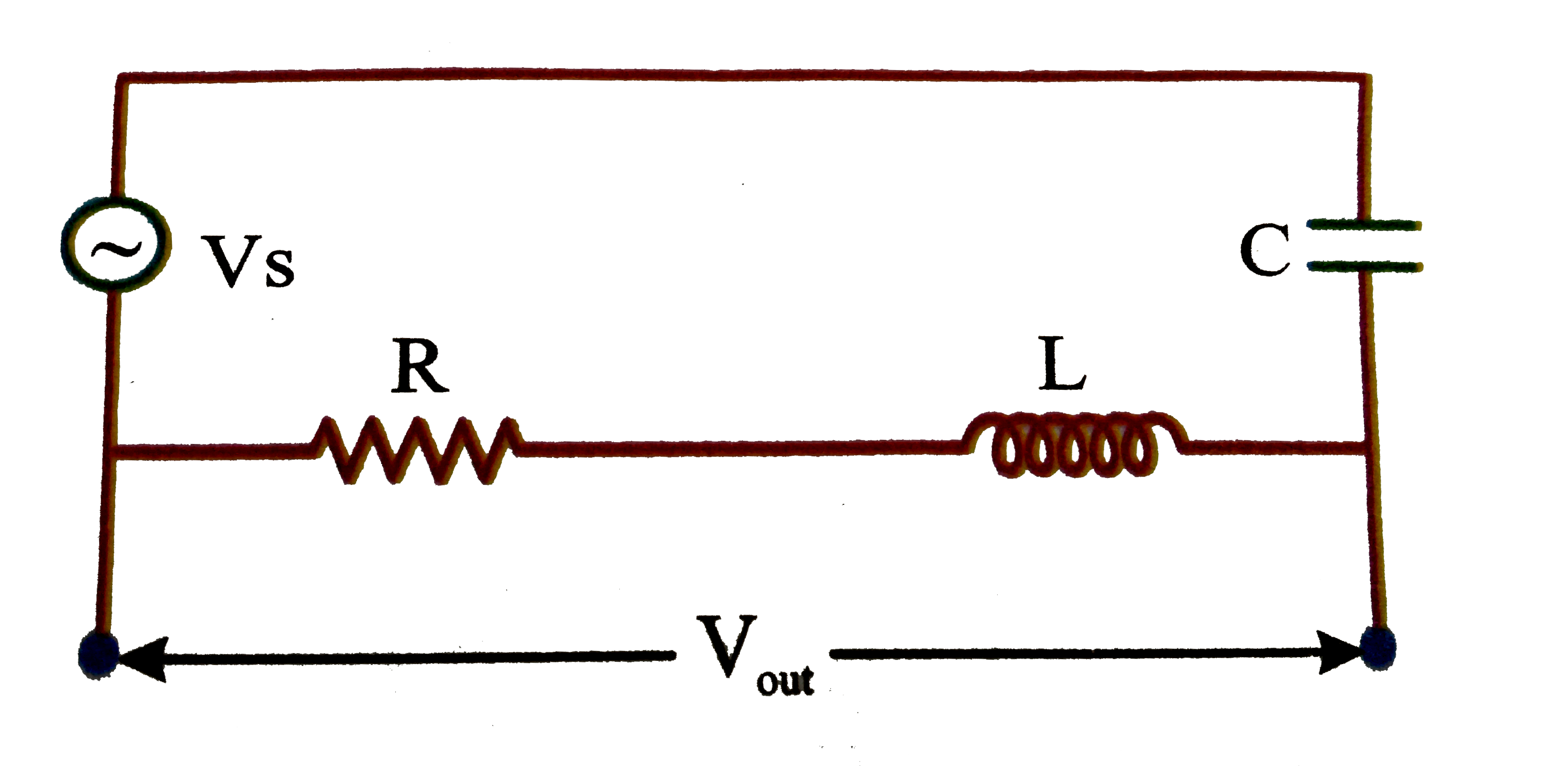
Which statement is correct in the limit of large frequency is reached? (for `V_("out")//V_(s))`
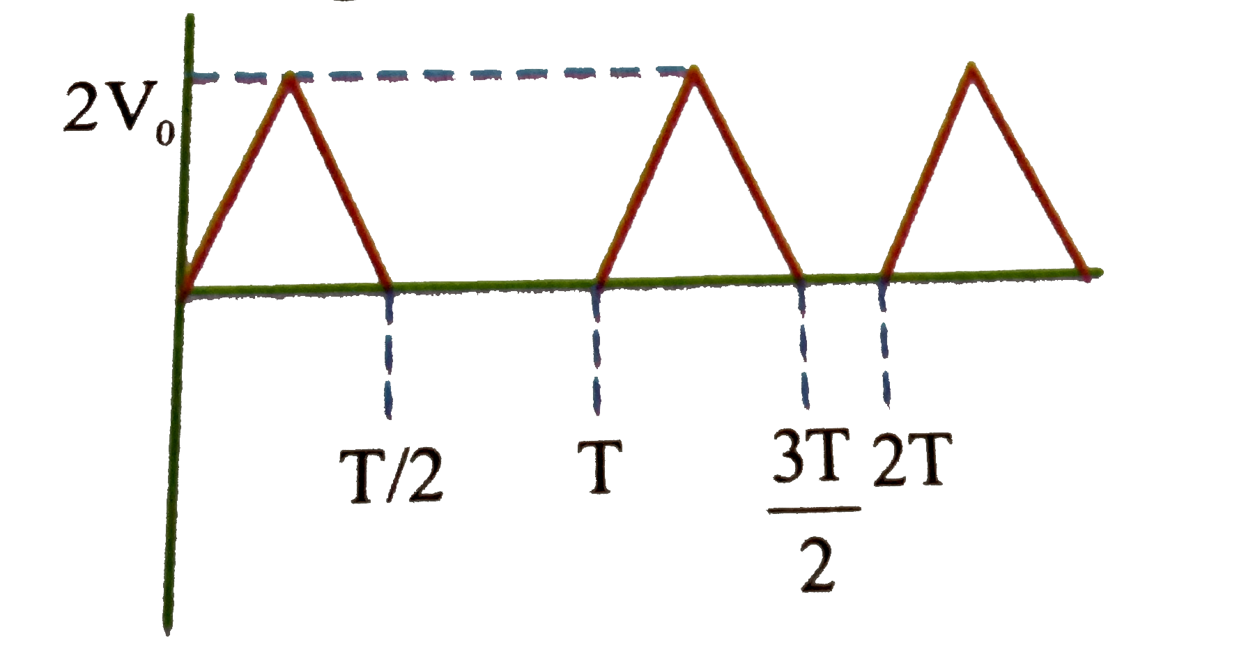
View SolutionIn `A.C` source peak value of `A.C` is the maximum value of current in either direction of the cycle. Root moon square `(RMS)` is also defined as the direct current which produces the same heating effect in a resistors as the actual `A.C`
`A.C` mesuring instrument measures its
View SolutionIn `A.C` source peak value of `A.C` is the maximum value of current in either direction of the cycle. Root moon square `(RMS)` is also defined as the direct current which produces the same heating effect in a resistors as the actual `A.C`
Current time graph of different souce is given which one will have `R.M.S` value `V_(0)`
View SolutionIn `A.C` source peak value of `A.C` is the maximum value of current in either direction of the cycle. Root moon square `(RMS)` is also defined as the direct current which produces the same heating effect in a resistors as the actual `A.C`
Average voltage for the given source is
View SolutionA steady `4 A` flows in an inductor coil when connected to a `12 V` source as shown in figure. If the same coil is connected to an ac source of `12 V`, `50 "rad"//s` a currentd of `2.4 A` flows in the circuit as shown in figure2. Now after these observations , a capacitor fo capacitance `(1)/(50) F` is connected in series with the coil and with same `AC` source as shown in figure 3.
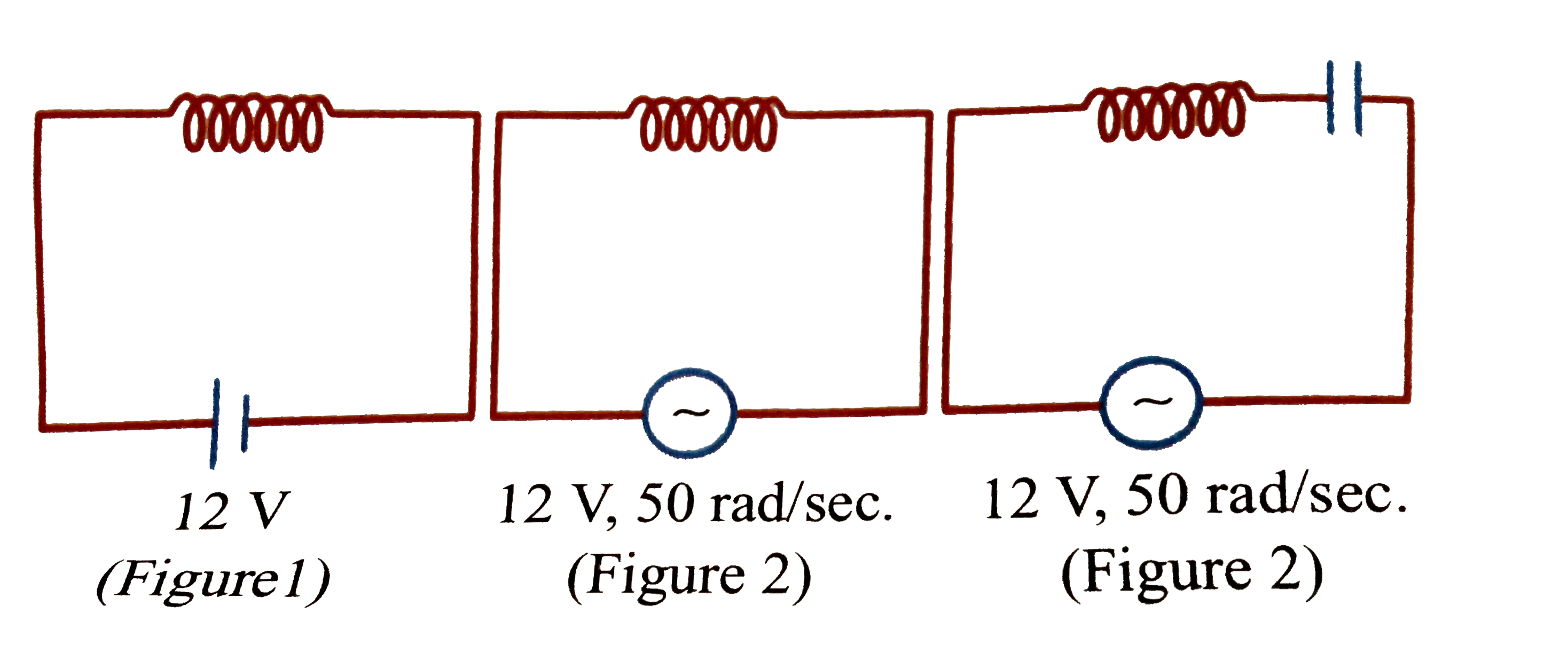
The resistance of the coil is:
View SolutionA steady `4 A` flows in an inductor coil when connected to a `12 V` source as shown in figure. If the same coil is connected to an ac source of `12 V`, `50 "rad"//s` a currentd of `2.4 A` flows in the circuit as shown in figure2. Now after these observations , a capacitor fo capacitance `(1)/(50) F` is connected in series with the coil and with same `AC` source as shown in figure 3.

The resistance of the coil is:
View SolutionA steady `4 A` flows in an inductor coil when connected to a `12 V` source as shown in figure. If the same coil is connected to an ac source of `12 V`, `50 "rad"//s` a currentd of `2.4 A` flows in the circuit as shown in figure2. Now after these observations , a capacitor fo capacitance `(1)/(50) F` is connected in series with the coil and with same `AC` source as shown in figure 3.

The resistance of the coil is:
View SolutionIn a series L-R circuit, connected with a sinusoidal ac source, the maximum potential difference across L and R are respectivaly 3 volts and 4 volts.
At an instant the potemtial difference across resistor is 2 volts. The potential difference in volt, across the inductor at the same instant will be:
View SolutionIn a series `L-R` circuit, connected with a sinusoidal ac source, the maximum potential difference acrosssd `L` and `R` are respectively 3 volts and 4 volts
At the same instant, the magnitude of the potential difference in volt, across the ac source will be
View SolutionIn a series `L-R` circuit, connected with a sinusoidal ac source, the maximum potential difference acrosssd `L` and `R` are respectively 3 volts and 4 volts
If the current at this instant is decreasing the magnitude of potential difference at that instant across the ac source is
View SolutionA constant voltage at a frequency of `1 MHz` is applied to an inductor in series with variable capacitor, when capacitor is `500 pF`, the current has its maximum value, while it is reduced to half when capacitance is `600 pF`. Find
Resistance `(R )`
View SolutionA constant voltage at a frequency of `1 MHz` is applied to an inductor in series with variable capacitor, when capacitor is `500 pF`, the current has its maximum value, while it is reduced to half when capacitance is `600 pF`. Find
The inductance `L`
View SolutionA constant voltage at a frequency of `1 MHz` is applied to an inductor in series with variable capacitor, when capacitor is `500 pF`, the current has its maximum value, while it is reduced to half when capacitance is `600 pF`. Find
`Q` factor of the circuit is
View SolutionWhen `1A` is passed through three coils `A,B,C` in series the voltage drops are respectively 6,3 and 8 volt on direct current source and 7,5 and 10 volt on Alternating current source
Power factor of coil `B`, will be
View SolutionWhen `1A` is passed through three coils `A,B,C` in series the voltage drops are respectively 6,3 and 8 volt on direct current source and 7,5 and 10 volt on Alternating current source
Power dissipated in coil `C`
View SolutionWhen `1A` is passed through three coils `A,B,C` in series the voltage drops are respectively 6,3 and 8 volt on direct current source and 7,5 and 10 volt on Alternating current source
Power factor of whole circuit when atlernating current flow
View SolutionA series circuit connected across a `200 V, 60 Hz` line consists of a capacitive reactance `30 Omega` non inductive resistor of `44 Omega` and a coil of inductive reactance `90 Omega` and resistance `36 Omega` as shown in the diagram
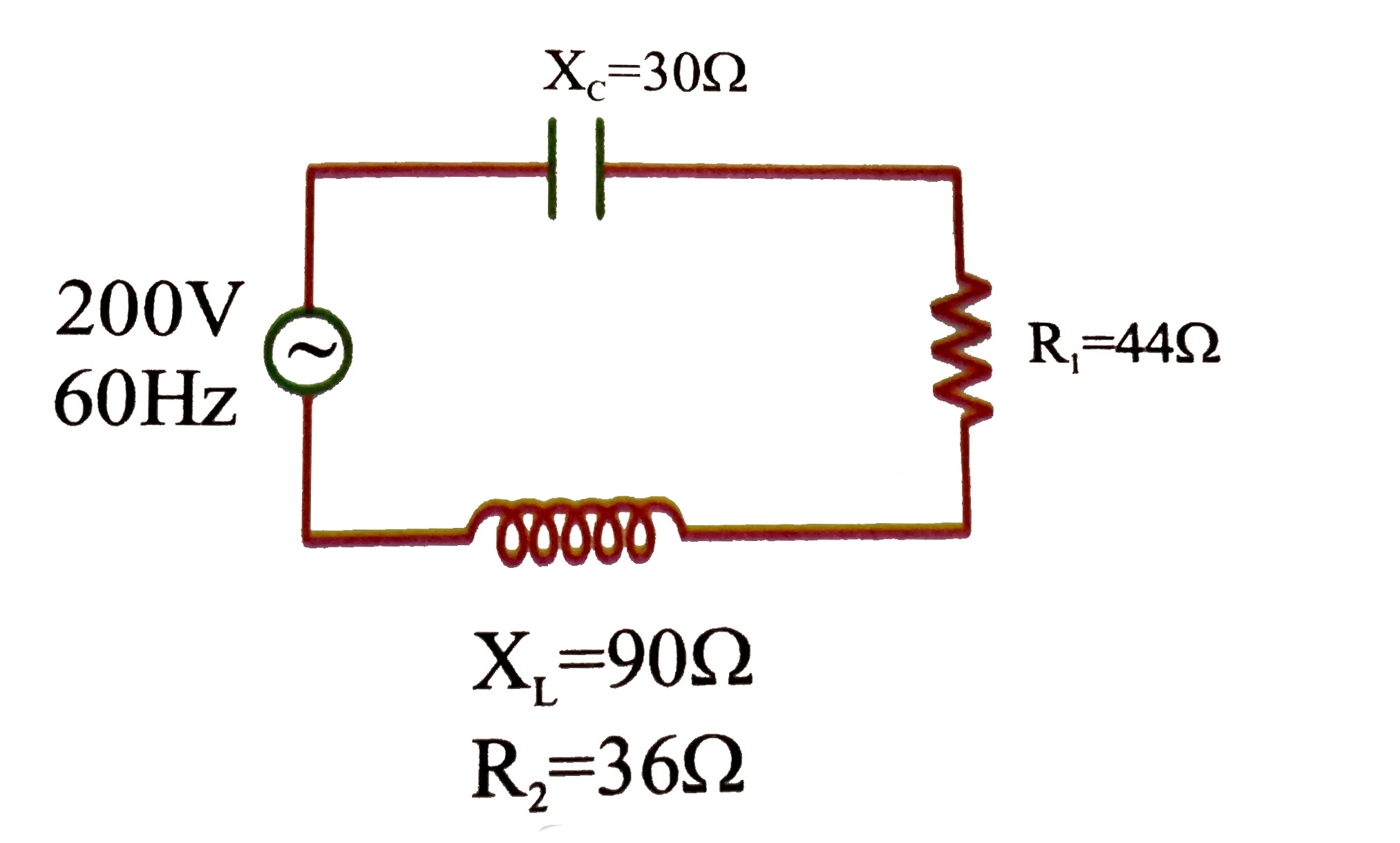
The potentail difference across the coil is
View SolutionA series circuit connected across a `200 V, 60 Hz` line consists of a capacitive reactance `30 Omega` non inductive resistor of `44 Omega` and a coil of inductive reactance `90 Omega` and resistance `36 Omega` as shown in the diagram
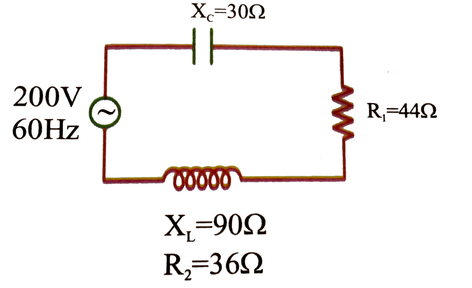
The power used in the circuit is
View SolutionA series circuit connected across a `200 V, 60 Hz` line consists of a capacitive reactance `30 Omega` non inductive resistor of `44 Omega` and a coil of inductive reactance `90 Omega` and resistance `36 Omega` as shown in the diagram
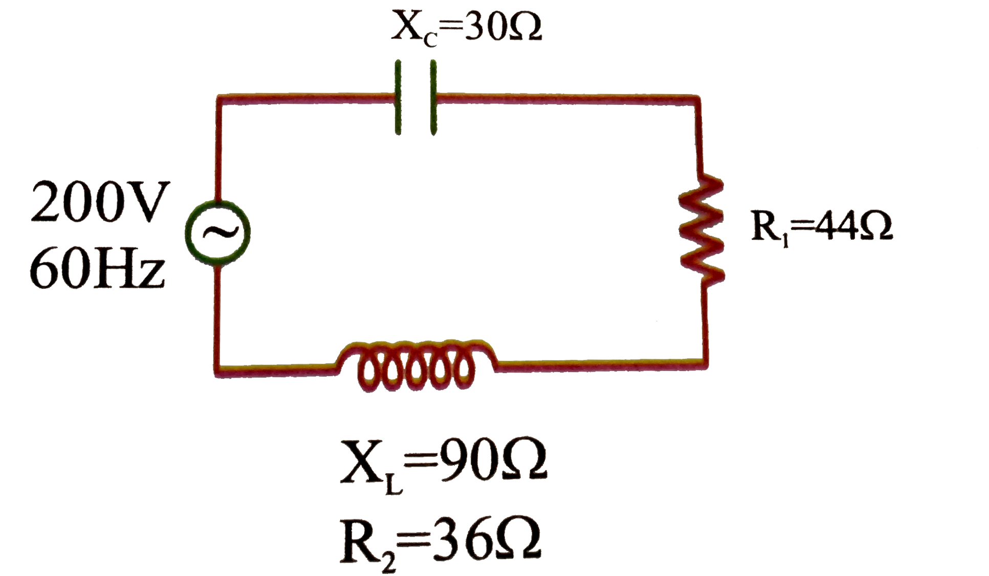
The power dissipated in the inductance coil is
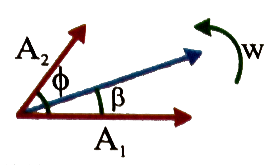
View SolutionThe maximum values of the phasors (currents and voltage) in `AC` circuits can be treated as vectors rotating with an angular frequency equal to the angular frequency of the rotor of the generator. If the phase difference between two phasors `vec(A_(1))` and `vec(A_(2))` is `phi` the resultant phasor is :
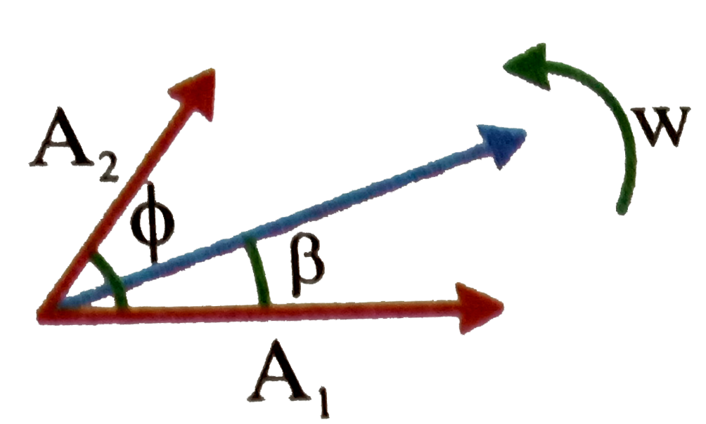
`A = sqrt(A_(1)^(2) + A_(2)^(2) + 2A_(1)A_(2) cos phi)`
and the phase of `vec(A)` with respects to `A_(1)` is
`beta = "tan"^(-1) (A_(2) sin phi)/(A_(1) + A_(2) cos phi)`
`RHS` value
The rms value of `y = f (t)` is
`y_("rms") = {(int_(0)^(T) [f(t)]^(2) dt)/(T)}^((1)/(2))`
Average value
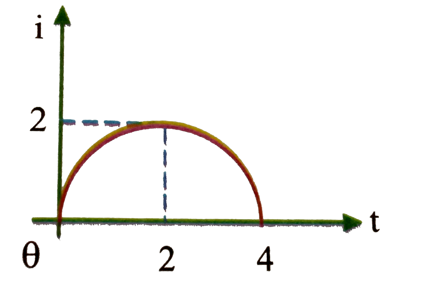
The average value of `y = f (t)` is `y_(av) = (int_(0)^(T) ydt)/(T)`
Using the above concept, answer the following questions.
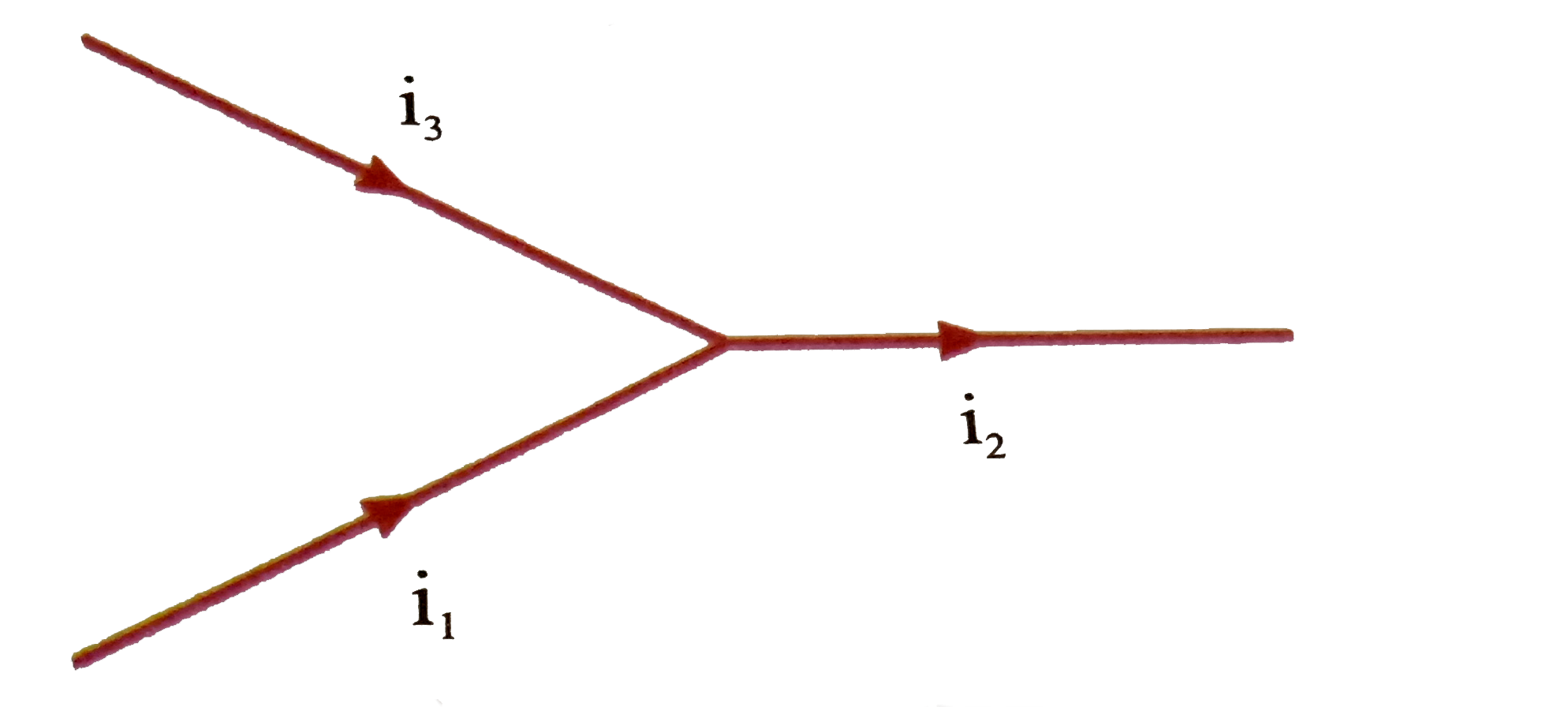
The current `i_(1)` and `i_(2)` in `A.C` circuit are given as: `i_(1) = 4 sin (omega t - (pi)/(3))` and `i_(2) = 4 sin (omega t + (pi)/(3))`
The current `i_(3)` can be given as :
View SolutionThe maximum values of the phasors (currents and voltage) in `AC` circuits can be treated as vectors rotating with an angular frequency equal to the angular frequency of the rotor of the generator. If the phase difference between two phasors `vec(A_(1))` and `vec(A_(2))` is `phi` the resultant phasor is :
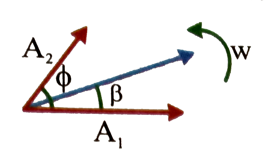
`A = sqrt(A_(1)^(2) + A_(2)^(2) + 2A_(1)A_(2) cos phi)`
and the phase of `vec(A)` with respects to `A_(1)` is
`beta = "tan"^(-1) (A_(2) sin phi)/(A_(1) + A_(2) cos phi)`
`RHS` value
The rms value of `y = f (t)` is
`y_("rms") = {(int_(0)^(T) [f(t)]^(2) dt)/(T)}^((1)/(2))`
Average value
The average value of `y = f (t)` is `y_(av) = (int_(0)^(T) ydt)/(T)`
Using the above concept, answer the following questions.
The rms value of `i_(3)` is
View SolutionThe maximum values of the phasors (currents and voltage) in `AC` circuits can be treated as vectors rotating with an angular frequency equal to the angular frequency of the rotor of the generator. If the phase difference between two phasors `vec(A_(1))` and `vec(A_(2))` is `phi` the resultant phasor is :
`A = sqrt(A_(1)^(2) + A_(2)^(2) + 2A_(1)A_(2) cos phi)`
and the phase of `vec(A)` with respects to `A_(1)` is
`beta = "tan"^(-1) (A_(2) sin phi)/(A_(1) + A_(2) cos phi)`
`RHS` value
The rms value of `y = f (t)` is
`y_("rms") = {(int_(0)^(T) [f(t)]^(2) dt)/(T)}^((1)/(2))`
Average value
The average value of `y = f (t)` is `y_(av) = (int_(0)^(T) ydt)/(T)`
Using the above concept, answer the following questions.
The average value of `i` in `i - t` graph (Semi circular) is
View SolutionA series `R-L-C` circuit has `R = 100` ohm. `L = 0.2 mH` and `C = (1)/(2) mu F`. The applied voltage `V = 20 sin omega t`. Then
At resonant frequency `omega_(0), ((V_(R ))_("max"))/((V_(L))_("max")) =`
View SolutionA series `R-L-C` circuit has `R = 100` ohm. `L = 0.2 mH` and `C = (1)/(2) mu F`. The applied voltage `V = 20 sin omega t`. Then
When the currentsd lags the applied voltage by `45^(@)`, the value of `omega` is approximately
View SolutionA series `R-L-C` circuit has `R = 100 Ohm. L = 0.2 mH` and `C = (1)/(2) mu F`. The applied voltage `V = 20 sin omega t`.
When the current lags the applied voltage by `45^(@)`, the equation of the current is
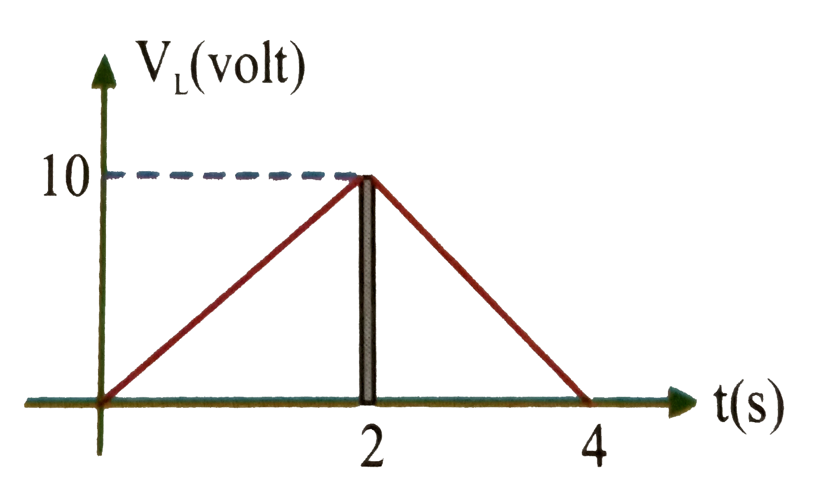
View SolutionThe potential difference across a `2 H` inductor as a function of time is shown in figure. At time `t=0`, current is zero
Current `t = 2` second is
View SolutionThe potential difference a `2 H` inductor as a function of time is shown in figure. At time `t = 0`, current is zero
Current versus time graph across the inductor will be
View SolutionIn the given arrangement the square loop of area `10 cm^(2)` rotates with an angular velocitys `omega` about its diagonal. The loop is connected to a inductance of `L = 100 mH` and a capacitance of `10 mF` in series. The lead wires have a net resistance of `10 Omega`. Given that `B = 0.1 T` and `omega = 63 "rad"//s`
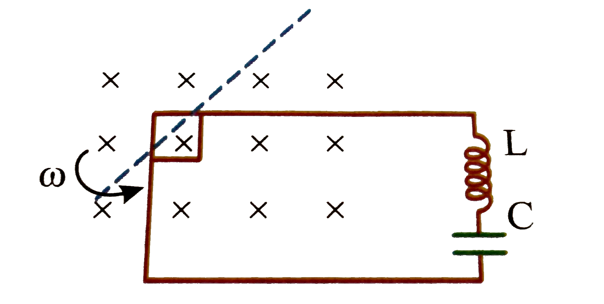
Find the rms current
View SolutionIn the given arrangement the square loop of area `10 cm^(2)` rotates with an angular velocitys `omega` about its diagonal. The loop is connected to a inductance of `L = 100 mH` and a capacitance of `10 mF` in series. The lead wires have a net resistance of `10 Omega`. Given that `B = 0.1 T` and `omega = 63 "rad"//s`

Find the rms current
View SolutionIn the given arrangement the square loop of area `10 cm^(2)` rotates with an angular velocitys `omega` about its diagonal. The loop is connected to a inductance of `L = 100 mH` and a capacitance of `10 mF` in series. The lead wires have a net resistance of `10 Omega`. Given that `B = 0.1 T` and `omega = 63 "rad"//s`
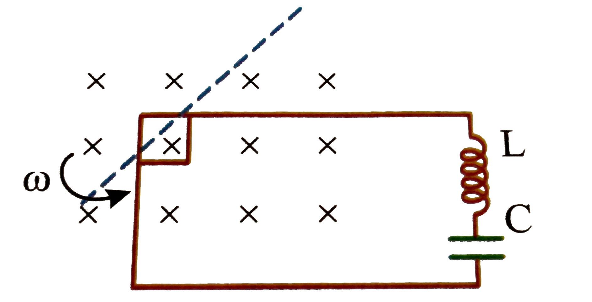
If the current is in phase with voltage, what shouldl be the frequency of rotation of the coil.
View SolutionA `20 V` 5 watt lamp is used in ac main `220 V` and frequency 50 c.p.s.
Capacitance of capacitor, to be put in series to run the lamp
View SolutionA `20 V` 5 watt lamp is used in ac main `220 V` and frequency 50 c.p.s.
Inductance of inductor,to be put in series to run tha lamp.
View SolutionA `20 V` 5 watt lamp is used in ac main `220 V` and frequency 50 c.p.s.
What pure resistance should be included in place of the above passive elements so that the lamp can run on its rated voltage?
View SolutionIn the circuit shown in the figure `R = 50 Omega, E_(1) = 25 sqrt(3)` volt and `E_(2) = 25 sqrt(6) sin omega t` volt where `omega = 100 pi s^(-1)`. The switch is closed at time `t = 0` and remains closed for 14 minutes, then it is opened.
Find the amount of heat produced in the resistor
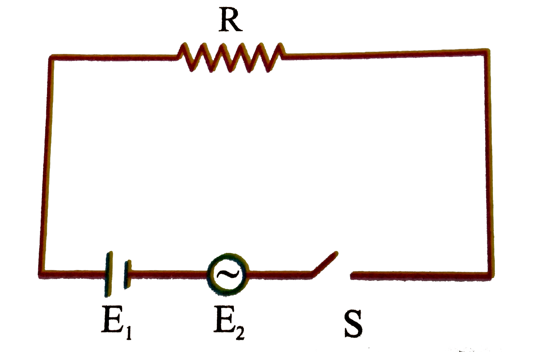
View SolutionIn the circuit shown in the figure `R = 50 Omega, E_(1) = 25 sqrt(3)` volt and `E_(2) = 25 sqrt(6) sin omega t` volt where `omega = 100 pi s^(-1)`. The switch is closed at time `t = 0` and remains closed for 14 minutes, then it is opened.
If total heat produced is usedd to raise the temperature of 3 kg of water at `20^(@)C`, what would be the final temperature of water ?
View SolutionIn the circuit shown in the figure `R = 50 Omega, E_(1) = 25 sqrt(3)` volt and `E_(2) = 25 sqrt(6) sin omega t` volt where `omega = 100 pi s^(-1)`. The switch is closed at time `t = 0` and remains closed for 14 minutes, then it is opened.
Find the value of the direct currentds that will produce same amount of heat in the resistor in same time as combination of `DC` source and `AC` source produce. Specific heat of water `= 4200 J//kg-^(@)C`.
View SolutionA physics lab is designed to study the transfer of electrial energy from one circuit to another by means of a magnetic field using simple transformers. Each transformer has two coils of wire electrically insulated from each other but wound a round a common core of ferromagnetic material. The two wires are close together but do not touch each other
The primary `(1^(@))` coil is connected to a source of alternating `(AC)` current. The secondary `(2^(@))` coil is connected to resistor such as a light bulb. The `AC` source produces on oscillating voltage and current in the primary coil that produces an oscillating megnetic field in the core. material. This in turn induces an oscillating voltage and `AC` curent in the secondary coil
Students collected the following data comparing the number of turns per coil `(N)`, the voltage `(V)` and the current `(I)` in the coils of three transformers.
`|{:("Transformer","primary coil","Secondary coil"),(1,100 . 10V.10A,200.20V.5A),(2,100.10V.10A,50.5V.5A),(3,100.10V.10A,100.5V.20A):}|`
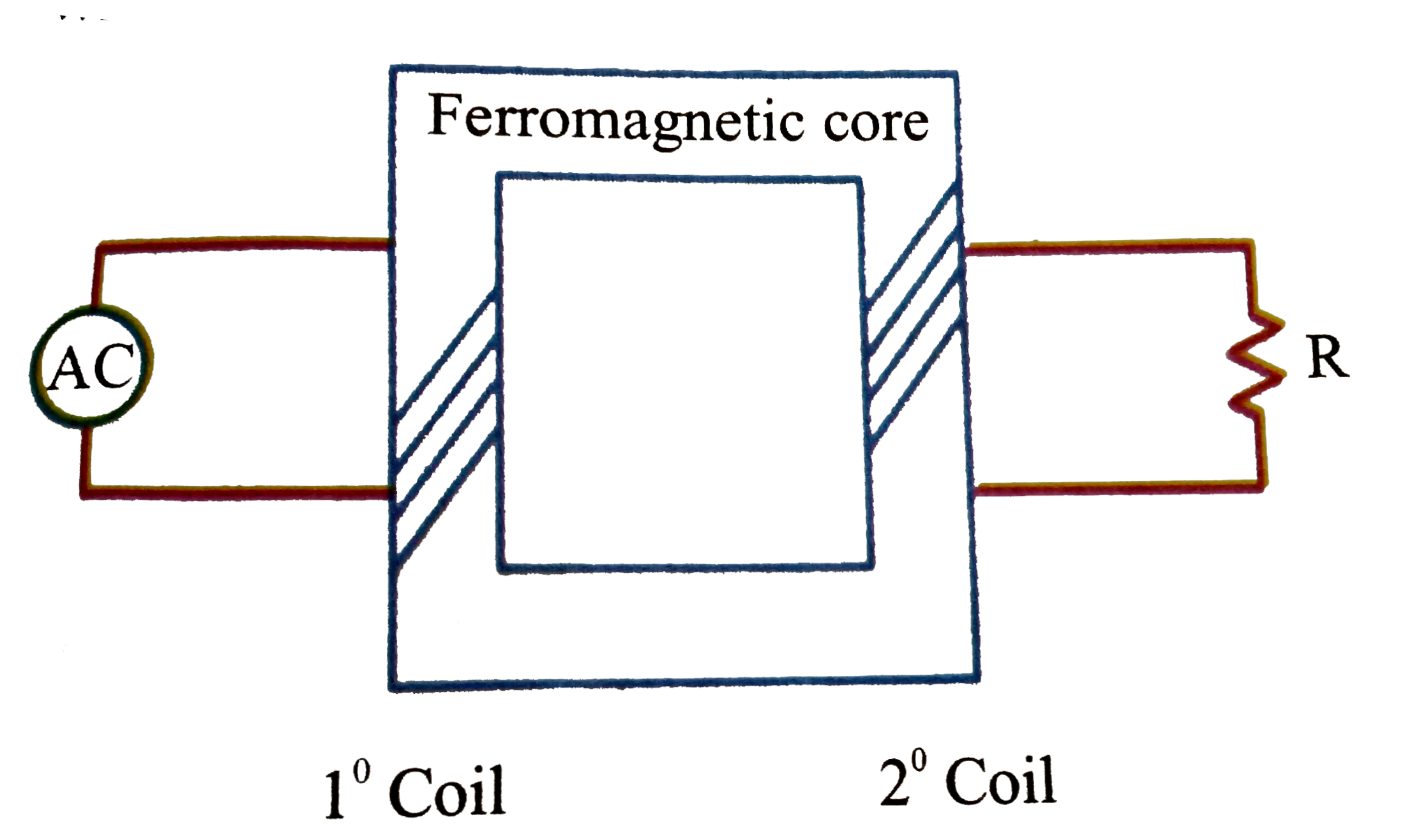
The primary coil of a transformer has 100 tunrs and is connected to a `120 V AC` source. How many turns are in the secondary coil if there is `2400 V` across it
View SolutionA physics lab is designed to study the transfer of electrial energy from one circuit to another by means of a magnetic field using simple transformers. Each transformer has two coils of wire electrically insulated from each other but wound a round a common core of ferromagnetic material. The two wires are close together but do not touch each other
The primary `(1^(@))` coil is connected to a source of alternating `(AC)` current. The secondary `(2^(@))` coil is connected to resistor such as a light bulb. The `AC` source produces on oscillating voltage and current in the primary coil that produces an oscillating megnetic field in the core. material. This in turn induces an oscillating voltage and `AC` curent in the secondary coil
Students collected the following data comparing the number of turns per coil `(N)`, the voltage `(V)` and the current `(I)` in the coils of three transformers.
`|{:("Transformer","primary coil","Secondary coil"),(1,100 . 10V.10A,200.20V.5A),(2,100.10V.10A,50.5V.5A),(3,100.10V.10A,100.5V.20A):}|`
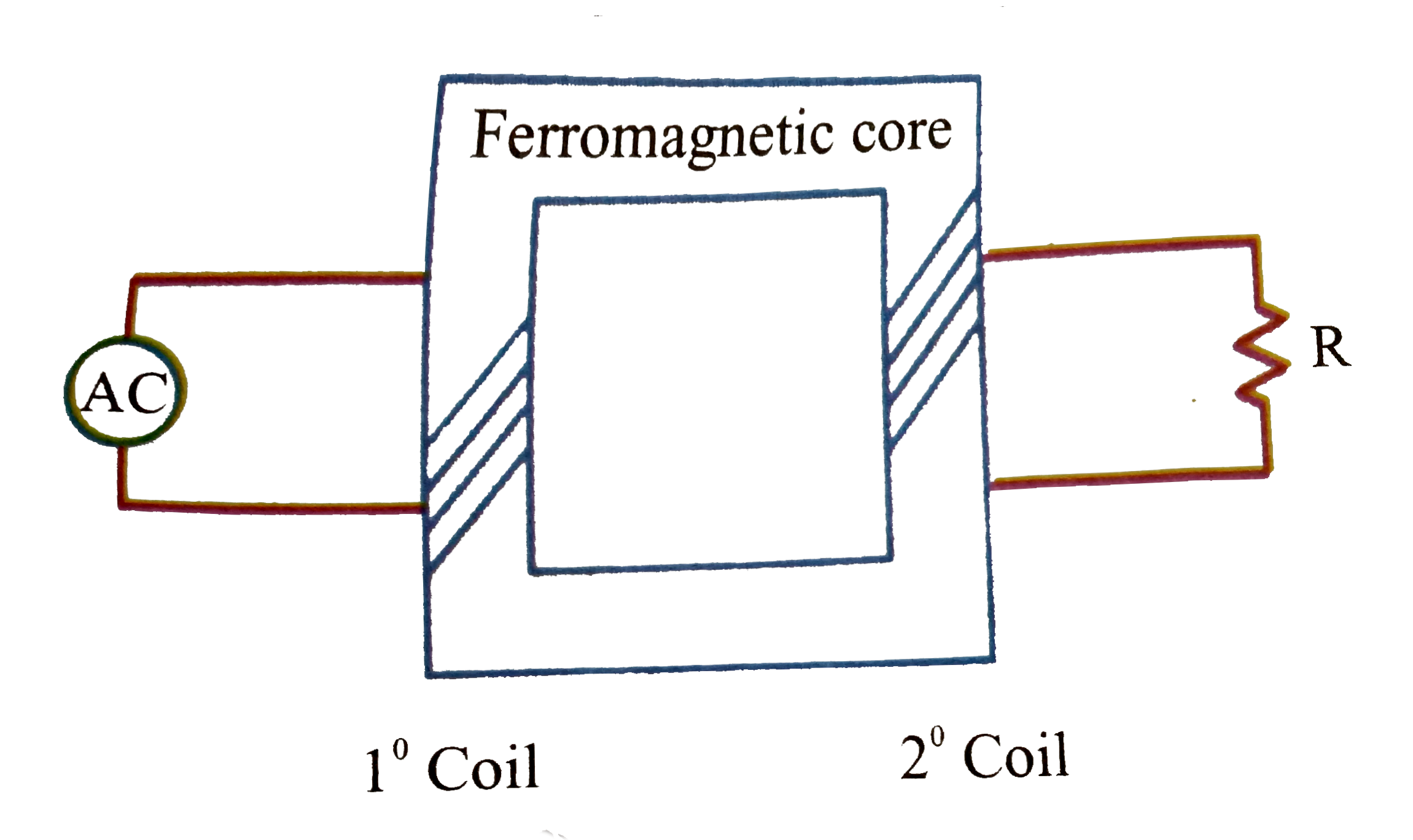
A trasnsformer with 40 turns in its primary coil is connected to a `120 V AC` source. If `20 W` of power if supplied to the primary coil, how much power is developed in the secondary coil ?
View SolutionA physics lab is designed to study the transfer of electrial energy from one circuit to another by means of a magnetic field using simple transformers. Each transformer has two coils of wire electrically insulated from each other but wound a round a common core of ferromagnetic material. The two wires are close together but do not touch each other
The primary `(1^(@))` coil is connected to a source of alternating `(AC)` current. The secondary `(2^(@))` coil is connected to resistor such as a light bulb. The `AC` source produces on oscillating voltage and current in the primary coil that produces an oscillating megnetic field in the core. material. This in turn induces an oscillating voltage and `AC` curent in the secondary coil
Students collected the following data comparing the number of turns per coil `(N)`, the voltage `(V)` and the current `(I)` in the coils of three transformers.
`|{:("Transformer","primary coil","Secondary coil"),(1,100 . 10V.10A,200.20V.5A),(2,100.10V.10A,50.5V.5A),(3,100.10V.10A,100.5V.20A):}|`
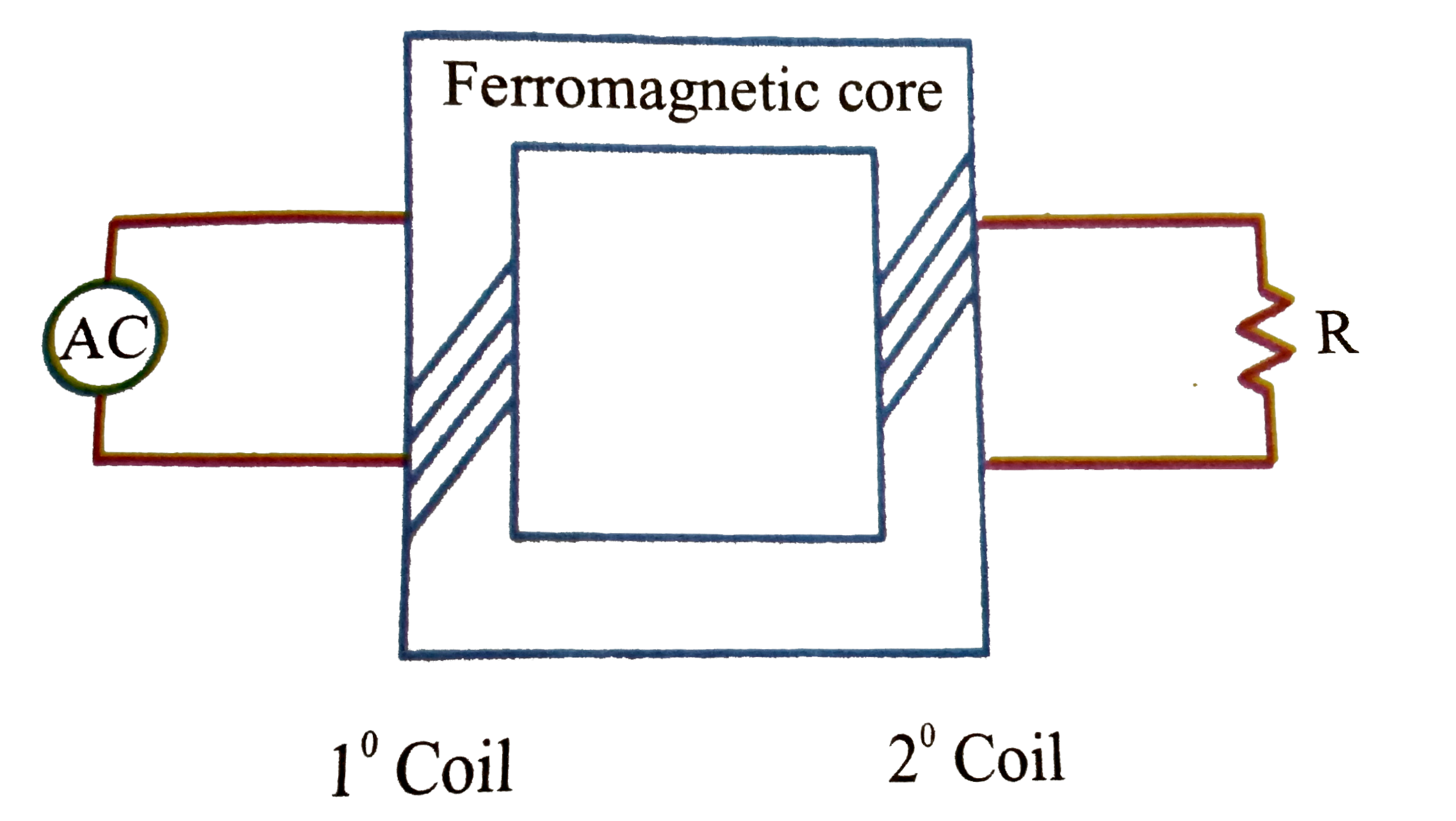
Which of the following is a correct expression for `R`, the resistance of the load connected to the secondary coil
View SolutionA physics lab is designed to study the transfer of electrial energy from one circuit to another by means of a magnetic field using simple transformers. Each transformer has two coils of wire electrically insulated from each other but wound a round a common core of ferromagnetic material. The two wires are close together but do not touch each other
The primary `(1^(@))` coil is connected to a source of alternating `(AC)` current. The secondary `(2^(@))` coil is connected to resistor such as a light bulb. The `AC` source produces on oscillating voltage and current in the primary coil that produces an oscillating megnetic field in the core. material. This in turn induces an oscillating voltage and `AC` curent in the secondary coil
Students collected the following data comparing the number of turns per coil `(N)`, the voltage `(V)` and the current `(I)` in the coils of three transformers.
`|{:("Transformer","primary coil","Secondary coil"),(1,100 . 10V.10A,200.20V.5A),(2,100.10V.10A,50.5V.5A),(3,100.10V.10A,100.5V.20A):}|`
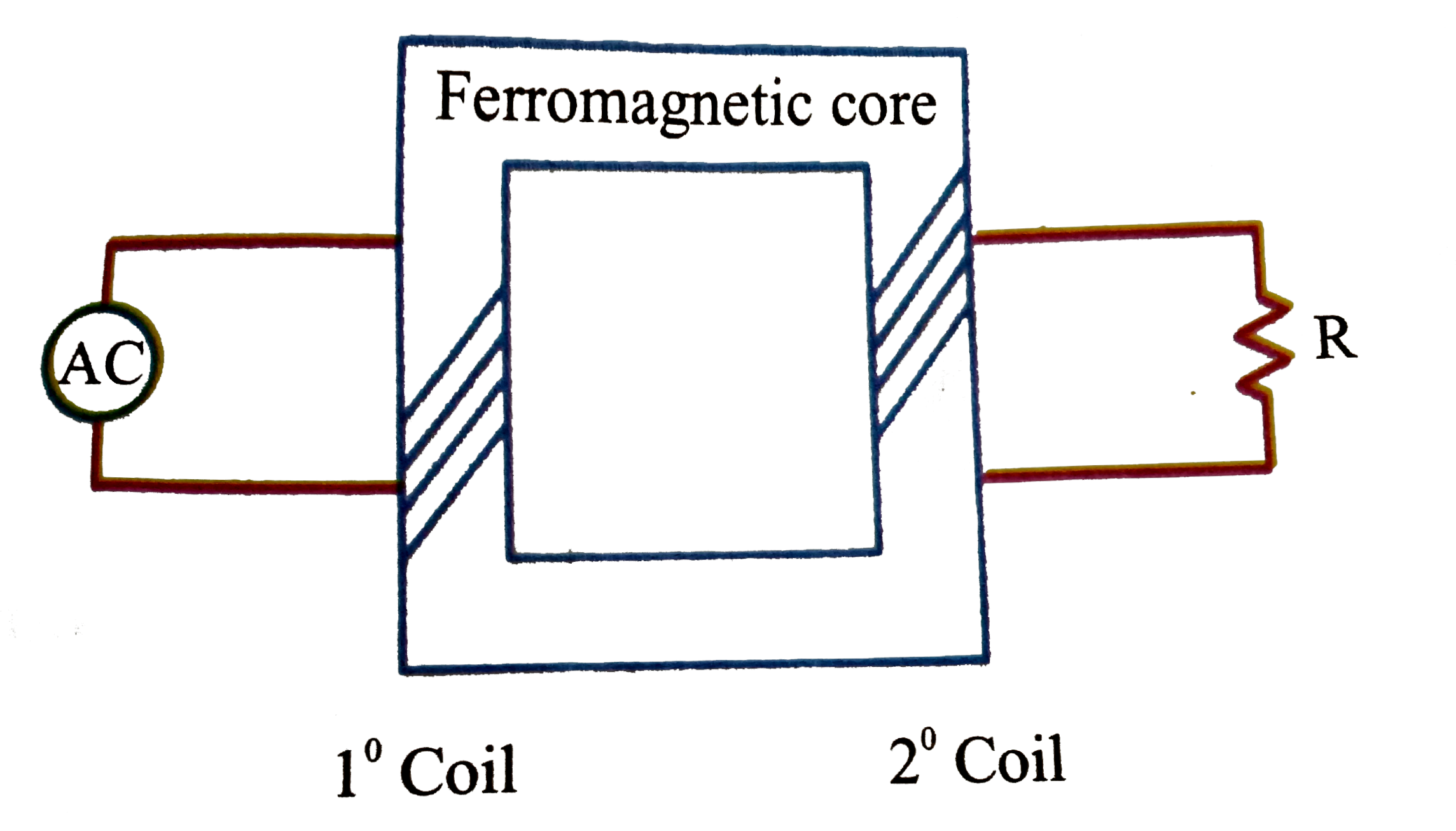
A `12 V` battery is used to supply `2.0 mA` of current to the 300 turns in the primary coil of a given transformer. What is the current in the secondary coil if `N_(2) = 150` turns.
View SolutionIn the circuit shown in figure :
`R = 10 Omega , L = (sqrt(3))/(10) H, R_(2) = 20 Omega` and `C = (sqrt(3))/(2) mF`. Current in `L - R_(1)` circuit is `I_(1)` in `C - R_(1)` circuit is `I_(2)` and the main current is `I`
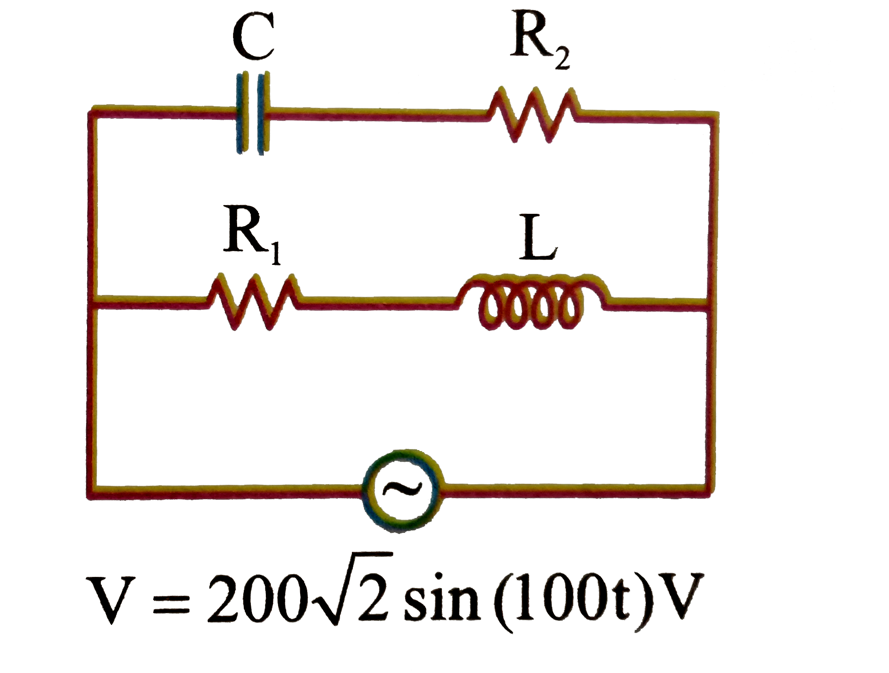
Phase difference between `I_(1)` and `I_(2)` is
View Solution
LEVEL - VI questions and complete solutions for chapter ALTERNATING CURRENT of NARAYANA PHYSICS (HINGLISH) of Class 12