Complete Solutions to PROBLEMS of chapter CAPACITANCE of Class 12 book with complete answers and questions
| Class 12 | PHYSICS |
| Chapter | CAPACITANCE |
| RESNICK AND HALLIDAY | PROBLEMS |
| Number Of Questions | 48 |
| Academic Year | 2023-24 |
In Fig. 25-25 `C_1=10.0 mu F, C_2=5.0 mu F and C_3=4.0 mu F` What is the change in their equivalent capacitance if (a) capacitors 1 and 2 are interchanged and (separately) (B) capacitors 1 and 3 are interchanged?
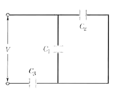
View SolutionIn Fig. 25-25 a potential difference V=75.0 V is applied across a capacitor arrangement with capacitances `C_1=10.0mu F, C_2=5.00 mu F, and C_3=15.0 mu F`. What are (a) charge `q_3` (b) potential difference `V_3` and ( c) stored energy `U_3` for capacitor 3, (d) `q_1` (e) `V_1 and (f) U_1` for capacitor 1, and (g) `q_2 (h) V_2` and (i) `U_2` for capacitor 2?
View SolutionIn fig.25-25 a potential arrangement with capacitances applied across a capacitor arrangement with capacitances `C_1=10.0 mu F,C_2=5.00 mu F, and C_3=4.00 mu F`. IF capacitor 3 undergoes electrical breakdown so that is becomes equivalent to conducting wire, then for capacitor 1 what are the increase in (a) charge, (b) potential difference, and ( c) stored energy
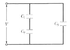
View SolutionIn Fig, 25-26 , find the equivalent capacitance of the combination. `C_1` is `10.0 mu F,C_2` is `8.00 muF`, and `C_3` is `4.00 mu F`
View SolutionWhat capacitance is required to store an energy of 10kW.h at a potential difference of 1700V?
View SolutionIn Fig.25-25 a potentila difference V=100V is applied across a capacitor arragnement with capacitances `C_1=10.0 mu F, C_2=5.00 mu F and C_3=2.00 mu F` What are (a) charge `q_3`, (B) potential difference `V_3` and (c ) stored energy `U_3` for capacitor 3 (d) `q_1` (v) `v_1` and (f) `U_2` for capacitor 1, and (g) `q_3 (h) V_2` and (i) `U_2` for capacitor 2?
View SolutionA parallel plate capacitor has plates of area `0.080m^2` and a separation of 1.2 cm . A battery charges the plates to a potential difference of 120V and is then disconnected . A dielectric slap of thickness 4.0mm and dielectric constant 4.8 is then placed symmetrically between the plates (a) What is the capacitance with the slab in place ? What is the free charge q (c) before and (d) after the slap is inserted ? What is the magnitude of the electric field (e) in the space between the plates and dielectric and (f) in the electric itself? (g) with the slab in place, what is the potential difference across teh plates (h) How much external work is involved in inserting the slab?
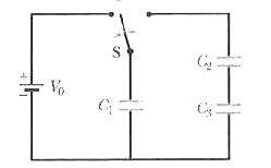
View SolutionFigure 25-27 displays a 16.0 V battery and 3 uncharged capacitors of capacitances `C_1=4.00 mu F, C_2=6.00 mu F and C_3=3.00 mu F` The switch is thrown to the left side until capacitor 1 is fully charged. Then the switch is thrown to the right. What is the final charge on (a) capacitor 1, (b) capacitor 2 and (c ) capacitor 3?
View SolutionIn fig 25-28, the battery has potential difference V=14.0 V `C_2=3.00 mu F, C_4=4.00 mu F` and all the capacitors are initially uncharged, when switch S s closed, a total charge of `12 mu C` passes through point a and a total change of `8.0 mu C` passes through point b. What are (a) `C_1` and (b) `C_3`?

View SolutionA parallel plate air filled capacitor having area `40 cm^2` and plate spacing 1.0 mm is charged to a potential difference of 500V. Find (a) the capacitance, (b) the magnitude of the charge on each plate ( c) the stored energy, (d) the electric field between the plates and (e ) the energy density between the plates.
View SolutionA dielectric material is to fill the space in a capacitor Initially, with only air in place, the capacitance is `8.0 mu F` With the dielectric material in place, the capacitor should store `3.2 mu J` at a maximum potential difference of 350.8V. (a) What dielectric constant is required? (b) Of the materials in Table 25-1, which material should be used?
View SolutionAN air filled parallel plate capacitor has a capacitance of 2.1 pF. The separation of the plates is doubled, and wax is inserted between them . The new capacitance is `2.6 p F` Find the dielectric constant of the wax.
View SolutionA `2.0 mu F` capacitor and a `4.0 mu F`, capacitor are connected in parallel across in 300V potential difference (a) What is the total energy stored by them? (b) They are next connected in series across that potential difference. What is the ratio of the total energy stored by them in the parallel arrangement to that in the series arrangement?
View SolutionIn fig25-29, how much charge is stored on the parallel-plate capacitors by the 10.0 V battery? One is the filled with air, and the other the filled with a dielectric for which k=3.00,both capacitors have a plate area of `5.00 times 10^-3 m^2` and a plate separation of 2.00 mm.
View SolutionAssume that a stationary electron is a point of charge . What is the energy density u of its electric field at radial distances (a) r=1.00 mm, (b) r=1.00 `mu m` ( c) r=1.00 nm (d) r=1.00 pm, and (e ) r=1.00 fm (f) What is the u in the limit as `r to 0`?
View SolutionYou are asked to construct a capacitor having a capacitance near 1 n F and a breakdown potential in excess of 10,000 V. You think of using the sides of a tail pyrex drinking glass as a dielectric lining the inside and outside curved surfaces with aluminium foil to act as the plates. The glass is 10cm tall with an inner radius of 3.6 cm and an outer radius of 3.8 cm What are the (a) capacitance and (b) breakdown potential of this capacitor?
View SolutionThe parallel plates in a capacitor, with a plate area of `8.50 cm^2` and an air filled separation of 8.00 mm are charged by a 16.0 battery . Then are then disconnected from the battery and pushed together (without discharge) to a separation of 3.00 mm. Neglecting fringing the (a) the potential difference between the plates (b) the initial stored energy (c ) the final stored energy and (d) the (negative) work is pushing them together.
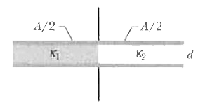
View SolutionFigure 25-30 shows a parallel plate capacitor with a plate area `A=5.56 cm^2` separation d=5.56 mm. The left half of the gap is filled with material of dielectric constant `k_1=7.00`, the right half is filled with material of dielectric constant `k_2=10.0` what is the capacitance?
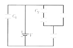
View SolutionIn fig 25-31 `C_1=10.0 mu F, C_2=20.0 mu F and C_3=5.00 mu F` If no capacitor can withstand a potential difference of more than 100V without failure , what are (a) the magnitude of the maximum potential difference that can exist between points A and B and (b) the maximum energy that can be stored in the three capacitor arrangement?

View SolutionA coaxial cable used in transmission line has an inner radius of 0.10 mm and an outer radius of 0.40mm. Calculate the capacitance per meter for the cable. Assume that the space between the conductors is filled with epoxy resin with dielectric constant 3.6.
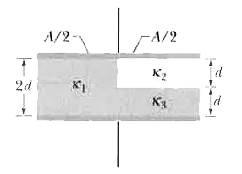
View SolutionFigure 25-32 shows a parallel plate capacitor of plate area `A=12.5 cm^2` and plate separation 2d=7.12mm. The left half of the gap is filled with material of dielectric constant `k_1=21.0` the top of the right half is filled with material of dielectric constant `k_2=42.0` the bottom of the right half is filled with material of dielectric constant `k_3=58.0` What is the capacitance?
View SolutionA parallel plate capacitor has square plates with ege length 8.20 cm and 1.30 mm separation. (a) Calculate the capacitance. (b) Find the charge for a potential difference of 120V.
View SolutionIn Fig 25-33 the battery has a potential difference of V=12.0 V and the five capacitors each have a capacitance each have a capacitance of `10.0 mu F` What is the charge on (a) capacitor 1 and (b) capacitor 2?
View SolutionA parallel plate air filled capacitor has a capacitance of 50 pF. (a) IF each of its plates has an area of `0.30 m^2` What is the separation (b) IF the region between the plates is now filled with material having `k=5.6` What is the capacitance.
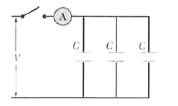
View SolutionEach of the uncharged capacitors in Fig 25-34 has a capacitance of `25.0 mu F`. A potential difference of V=750 V is established when the switch is closed . How many coulombs of charge then pass through meter A?
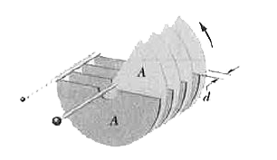
View SolutionFigure 25-35 shows a variable "air gap" capacitor for manual training Alternate plates are connected together, one group of plates is fixed in position, and the other group is capable is rotation. Consider a capacitor of n=8 plates of alternating polarity, each plate having area `A=1.50 cm^2` and separated from adjacent plates by distance d=3.40mm. What is the maximum capacitance of the device?
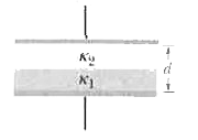
View SolutionFigure 25-36 shows a parallel plate capacitor with a plate area `A=789 cm^2` and plate separation d=4.62 mm. The top half of the gap is filled with material of dielectic constant `k_1=11.0`, the bottom half is filled with material of dielectric constant `k_2=4.0` What is the capacitance?
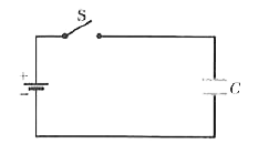
View SolutionTwo capacitor in Fig 25-37 has a capacitance of `30 mu F` and is initially uncharged. The battery provides a potential difference of 120 V. After switch S is closed, how much charge will pass through it?
View SolutionTwo parallel plate capacitors `8.0 mu F` each , are connected in parallel to a 10V battery. One of the capacitors is then squeezed so that its plate separation is 50.0% of its initial value. Because of the squeezing, (a) how much additional charge is transferred to the capacitors by the battery and (b) what is the increase in the total charge stored on the capacitors?
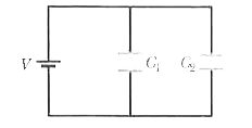
View SolutionIn figure the battery has a potential difference of `20 V`. Find
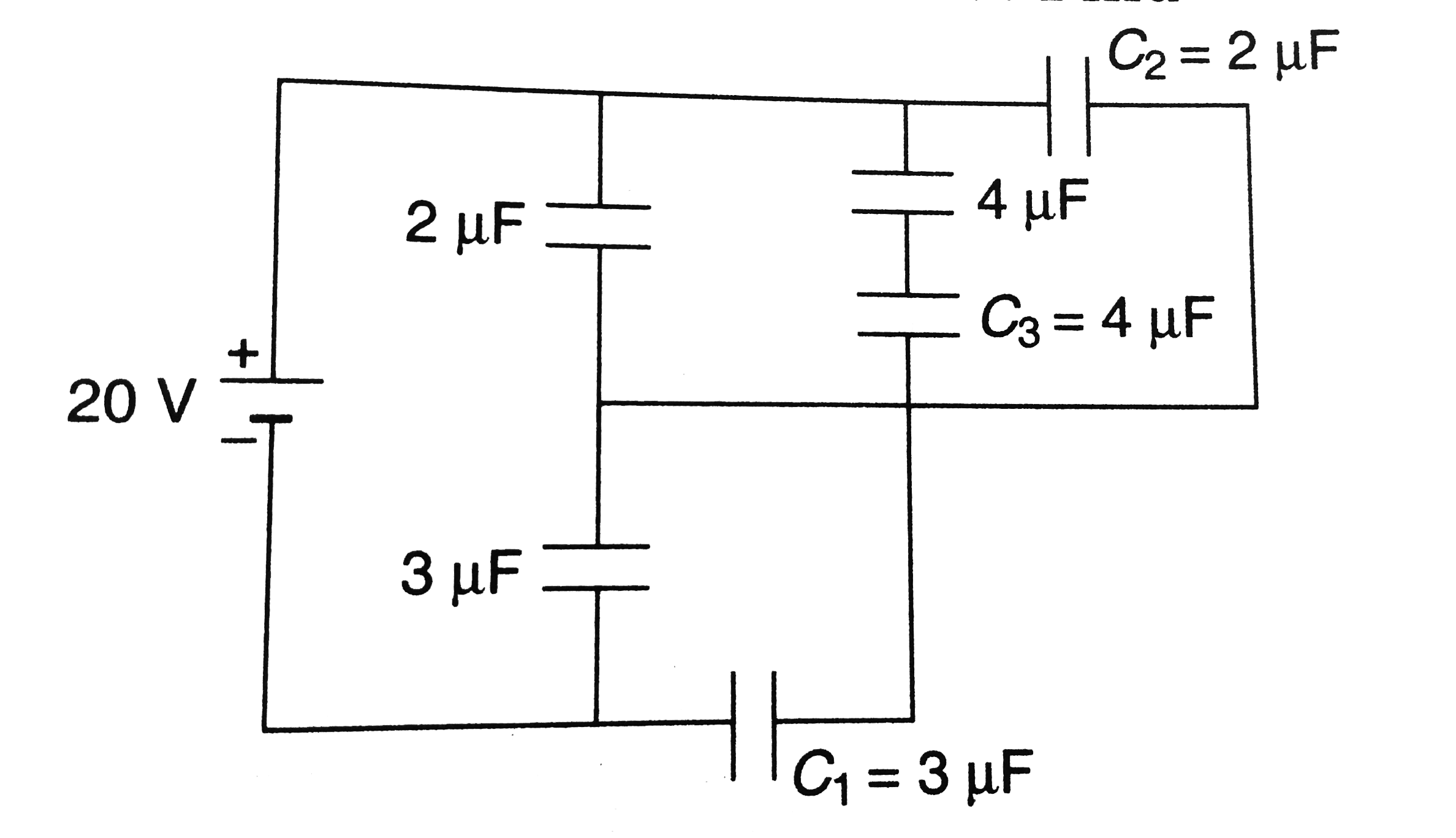
(a) the equivalent capacitance of all the capacitors across the battery and
(b) the charge stored on that, equivalent capacitance. Find the charge on
(c) capacitor 1,
(d) capacitor 2, and
(e) capacitor 3.
View SolutionA certan substance has a dielectric constant of 5.6 and a dielectric strength of `18 mV//m` . IF it is used as the dielectric material in a parallel plate capacitor. What minium area should the plates of the capacitor have to obtain a capacitance of `3.9 times 10^-2 mu F` and to ensure that the capacitor will be able to withstand a potential difference of 4.0 kV?
View SolutionFor the arrangement of Fig 25-22 suppose, that the battery remains connected while the dielectric slab is being introduced. Calculate (a) the capacitance (b) the charge on the capacitors plates (c ) the electric field in the gap and (d) the electric field in the slab after the slab is in place.
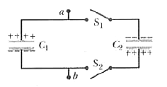
View SolutionIn fig 25-39 the capacitances are `C_1=1.0 mu F and C_2=3.0 mu F` and both capacitors are charged to a potential difference of V=200V but with opposite polarity as shown. Switches `S_1 and S_2` are now closed. (a) What is the now the potential difference between points a and b? What now is the charge on capacitor (b) 1 and (c) 2?
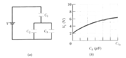
View SolutionCapacitor 3 in Fig. 25-40a is a variable capacitor (its capacitance `C_3` can be varied) Figure 25-40b gives the electric potential `V_1` across capacitor 1 versus `C_3` The horizontal scale is set by `C_3s=12.0 mu F` Electric potential `V_1` approaches as asymptote of 8.0 V as `C_3 to infty` What are (a) the electric potential V across the battery , (b) `C_1` and (c) `C_2`?
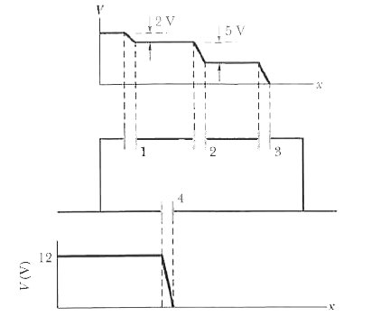
View SolutionFigure 25-41 shows a circuit section of four air filled capacitors that is connected to a larger circuit. The graph below the section shows the electrin potential V(x) as a function of position x along the lower part of the section, through capacitor 4. Similarly the graph above the section shows the electric potential V(x) as a function of position x along the upper part of the section, through capacitors 1,2 and 3 capacitors 3 has a capacitance of `1.60 mu F` What are the capacitances of (a) capacitor 1 and (b) capacitor 2?
View SolutionA charged isolated metal sphere of diameter 15cm has a potential of 6500V relative to V=0 at infinity. (a) calculate the energy density in the electric field near the surface of the sphere. (b) IF the diameter is decreased, does the energy density near the surface increase, decrease or remain the same?
View SolutionTwo parallel plates of area `100 cm^2` are given charges of equal magnitudes of`8.4 times 10^-7` C but opposite signs. The electric field within the dielectric material filling the space between the space is `1.4 times 10^ 6V//m` (a) Calculate the dielectric constant of the material. (b) Determine the magnitude of the charge induced on each dielectric surface.
View SolutionWhat is the capacitance of a drop that results when two mercury spheres, each of radius R=3.00 mm merge?
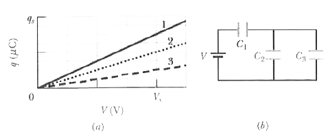
View SolutionPlot 1 in fig25-42a gives the charge q that can be stored on capacitor 1 versus the electric potential V set up across it. The vertical scale is set by `q_s=16.0 mu F` and the horizontal scale is set by `V_S=2.0V` Plots 2 and 3 are similar plots for capacitors 2 and 3 respectively. FIgure 25-42b shows a circuit that whose three capacitors and a 10.0V battery.What is the charge stored on capacitor 2 in that circuit?
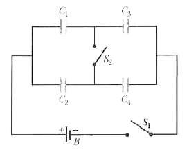
View SolutionFigure 25-43 shows a 24.0 V battery and four uncharged capacitors of capacitances `C_1=1.00 mu F, C_2=2.00 mu F C_3=3.00 mu F and C_4=4.00 mu F` IF only switch `S_1` is closed, what is the charge, on (a) capacitor 1 (b) capacitor 2 (c ) capacitor 3 and (d) capacitor 4? IF both switches are enclosed , what is the charge on (e) capacitors1.(f) capacitor 2, (g) capacitor 3, and (h) capacitor 4?
View SolutionHow many `12.5 mu F` capacitors must be connected in parallel to store a charge of 33.0m C with a potential of 110V across the capacitors?
View SolutionThe space between two concentric conducting spherical shells of radii b=1.70 cm and a=1.20 cm is filled with a substance of dielectric constant k=6.91 A. A potential difference V=73.0 V is applied across the inner and outer shells Determine (a) the capacitance of the device (b) the free charge q on the inner shell, and (c) the charge q induced along the surface of the inner shell?
View SolutionYou have two flat metal plates, each of area `1.00 m^2` with which to construct a parallel plate capacitor (a) If the capacitance of the device is to be 2.00F what must be the separation between the plates? (b) could this capacitor actually be constructed?
View SolutionThe two metals objects in Fig 25-44 have net charges of +70pC and -70pC which result in a 35V potential difference between them (a) What is the capacitance of the system? (b) If the charges are changed to +200pC and -200pC, what does the capacitance become ? (c) what does the potential difference become?

View SolutionIn fig.25-45 V=12V `C_1=10 mu F and C_2=C_3=20 mu F` Switch S in first thrown to the left side until capacitor 1 reaches equilibrium. Then the switch is thrown to the right when equilibrium is again reached, how must charge is on capacitor 1?

View SolutionA 100pF capacitor is charged to a potential difference of 80.0V and the charging battery is disconnected. The capacitor is then connected in parallel with a second capacitor. If the potential difference across the first capacitor drops to 35.0 V what is the capacitance of this second capacitor?
View SolutionThe plates of a spherical capacitor havi radii 37.0mm and 40.00 mm (a) calculate the capacitance. (b) What must be the plate area of a parallel plate capacitor with the same plate separation and capacitance?
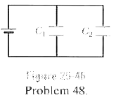
View SolutionIn fig.25-46 two parallel plate capacitors (with air between the plates) are connected to a battery. Capacitor 1 has a plate area of `1.5 cm^2` and an electric field of magnitude `3500 V//m`. Capacitor 2 has a plate area of `0.70 cm^2` and an electric field of magnitude `1500 V//m` (a) What is the total charge on the two capacitors? (b) If the first plate area is cut in half does the total charge increase, decrease, on remain the same?
View Solution
PROBLEMS questions and complete solutions for chapter CAPACITANCE of RESNICK AND HALLIDAY PHYSICS (HINGLISH) of Class 12