What is the output of the combination of the gates shown in the fig. below?A A + A ∙ BB A + A ∙ BC A + B ∙ A ∙ BD A + B ∙ A + B
The correct option is A A + A ∙ B.Explanation:C = A + Y and Y = AB ∴ C = A + AB
Related Solutions
The output of the combination of the gates shown in the figure below is .
View SolutionSelect the outputs Y of the combination of gates shown below for inputs A = 1,B = 0 , A = 1,B = 1 and A = 0,B=0 respectively :-
View SolutionSelect outputs Y of the combination of gates shown below for inputs A = 1 , B = 0 , A = 1 , B = 1 and A = 0 , B = 0 respectively.
View SolutionSelect the outputs Y of the combination of gates shown below for inputs A = 1,B = 0 , A = 1,B = 1 and A = 0,B=0 respectively :-
View SolutionSelect the outputs Y of the combination of gates shown below for inputs and respectively :-
_E01_437_Q01.png) View Solution
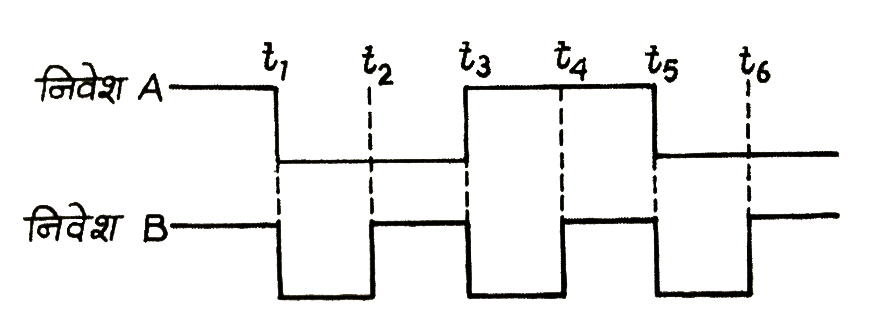
View Solutionनीचे दिखाए गए निवेश A तथा B के लिये NAND गेट के निर्गत तरंग रूप को स्केच कीजिए :
 View Solution
नीचे दिखाए गए निवेश A तथा B के लिये NAND गेट के निर्गत तरंग रूप को स्केच कीजिए :
 View Solution
नीचे दिखाये गए निवेश A तथाB के लिएNAND गेट के निर्गत तरंग -रूप को स्केच कीजिये ।
View SolutionFor the given combination of gates shown in Fig., find the values of output y_(1) and y_(2) in the table given below Fig. Identify the gates I and II.
View SolutionThe output of the combination of the gates shown is
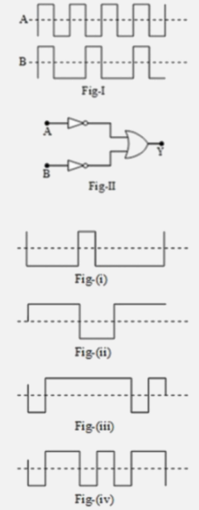
View SolutionInput waveforms A and B as shown in Fig-l are applied to the combination of gates as shown in Fig-ll. Which of the waveforms shown in Fig.(i) to (iv) correctly represents the output waveform?
 View Solution
Input waveforms A and B as shown in Fig-l are applied to the combination of gates as shown in Fig-ll. Which of the waveforms shown in Fig.(i) to (iv) correctly represents the output waveform?
View SolutionInput waveforms A and B as shown in Fig-l are applied to the combination of gates as shown in Fig-ll. Which of the waveforms shown in Fig.(i) to (iv) correctly represents the output waveform?
 View Solution
What is the output of the gate combination shown in the figure?
View SolutionFig, shows a logic gate circuit with two input A and B and the output C. The voltage wave form of A, B and C are as shown in Fig.The logic gate circuit is
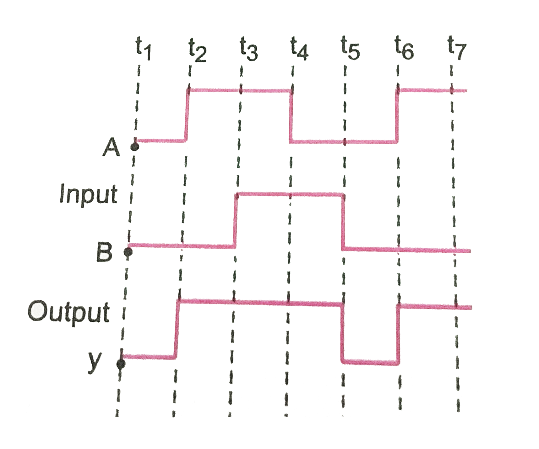
View SolutionThe Fig shown input waveforms A and B to a logic gate. Draw the output waveform for an OR gate. Write the truth table for this logic gate and draw its logic symbol.
 View Solution
The Fig shown input waveforms A and B to a logic gate. Draw the output waveform for an OR gate. Write the truth table for this logic gate and draw its logic symbol.
View SolutionThe following shows a logic gate circuit with two inputs A and B and the output C. The voltage waveforms of A, B and C are as shown below.
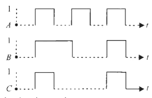
The logic circuit gate isView SolutionThe following figure shows a logic gate circuit with two inputs A and B and the output C. The voltage waveforms of A, B and C are as shown below.
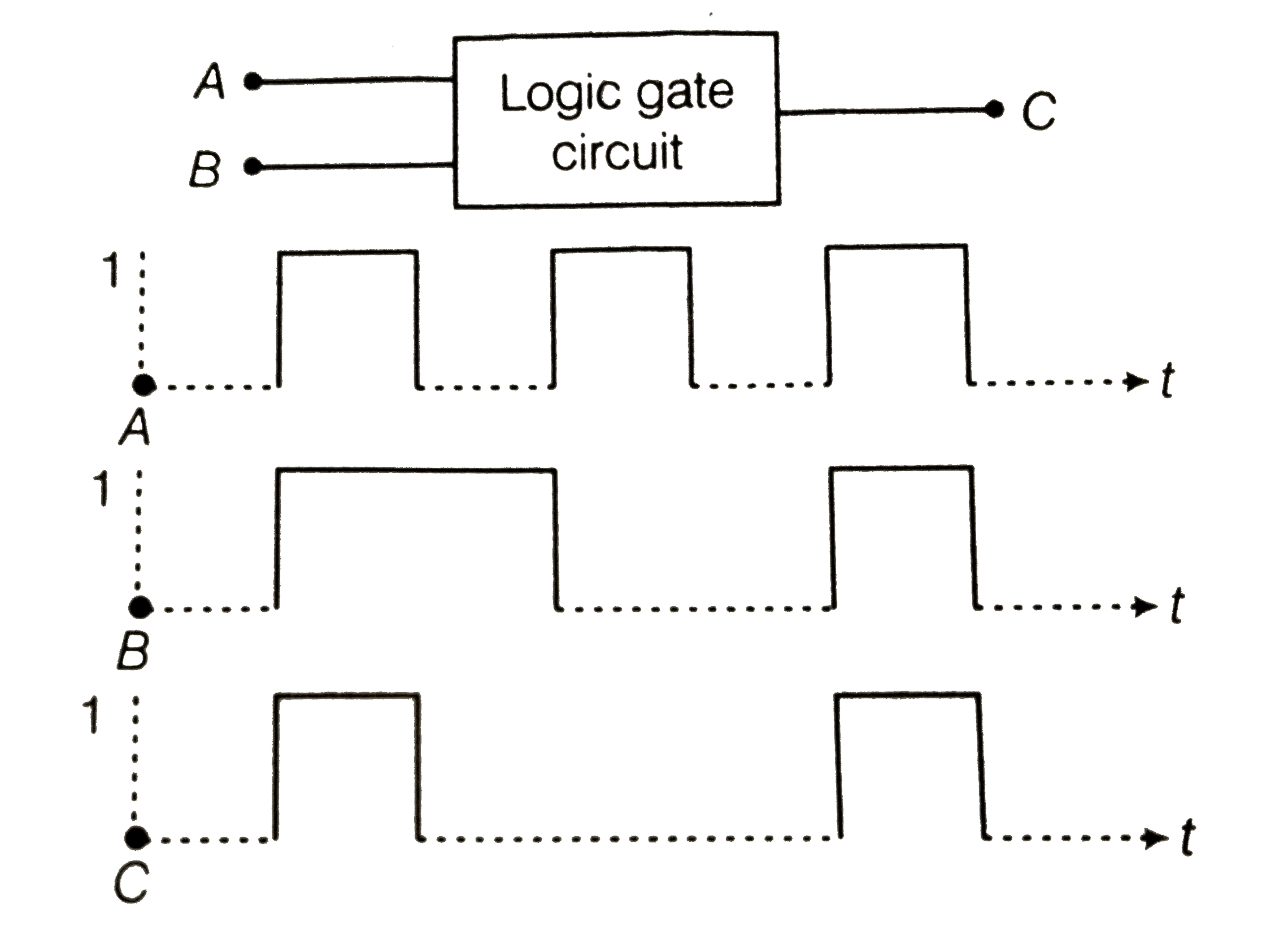
The logic circuit gate isView SolutionThe following figure shows a logic gate circuit with two inputs A and B and the output C. The voltage waveforms of A, B and C are as shown below
The logic circuit gate isView Solution
