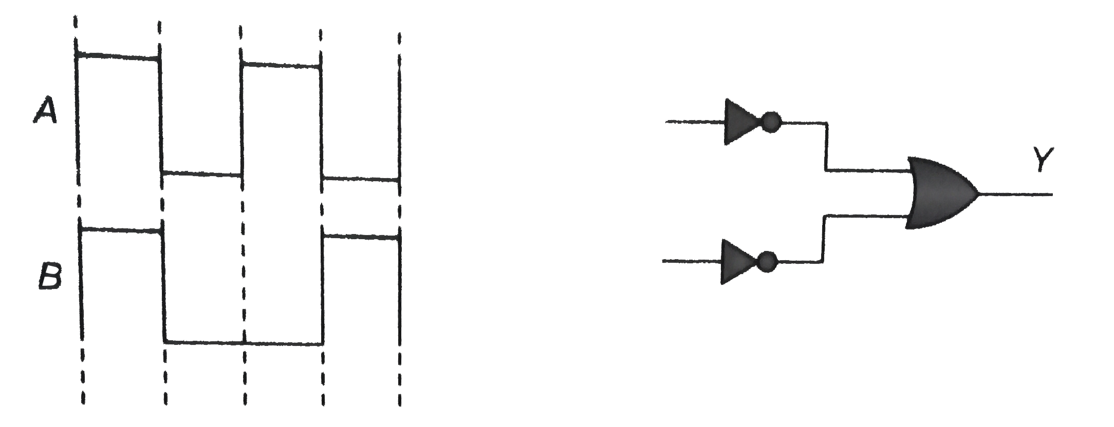
In a given circuit as shown the two input wave forms A and B are applied simultaneously.
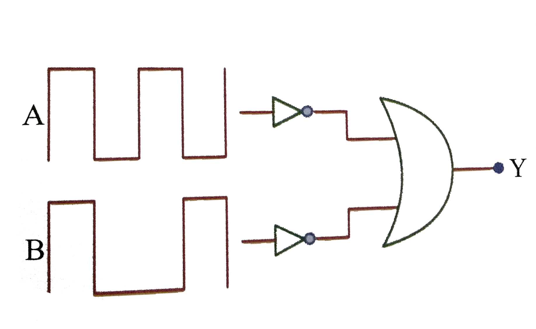
The resultant wave format at Y is.


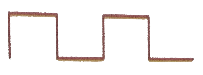

The correct Answer is:A
Logic of A is 1010, Logic of B is 1001
Logic of Y is 0111.
Topper's Solved these Questions
- BOOK - NARAYNACHAPTER - SEMI CONDUCTOR DEVICESEXERCISE - Level-III (C.W)20videos
SEMI CONDUCTOR DEVICES
- BOOK - NARAYNACHAPTER - SEMI CONDUCTOR DEVICESEXERCISE - NCERT (Comprehension)13videos
SEMI CONDUCTOR DEVICES
- BOOK - NARAYNACHAPTER - SEMI CONDUCTOR DEVICESEXERCISE - Level-I (C.W)21videos
SEMI CONDUCTOR DEVICES
- BOOK - NARAYNACHAPTER - RAY OPTICS AND OPTICAL INSTRAUMENTS EXERCISE - EXERCISE- 4 One or more than one correct answer type13videos
RAY OPTICS AND OPTICAL INSTRAUMENTS
- BOOK - NARAYNACHAPTER - SEMICONDUCTOR ELECTRONICSEXERCISE - ADDITIONAL EXERCISE (ASSERTION AND REASON TYPE QUESTIONS :)19videos
SEMICONDUCTOR ELECTRONICS
Similar Questions
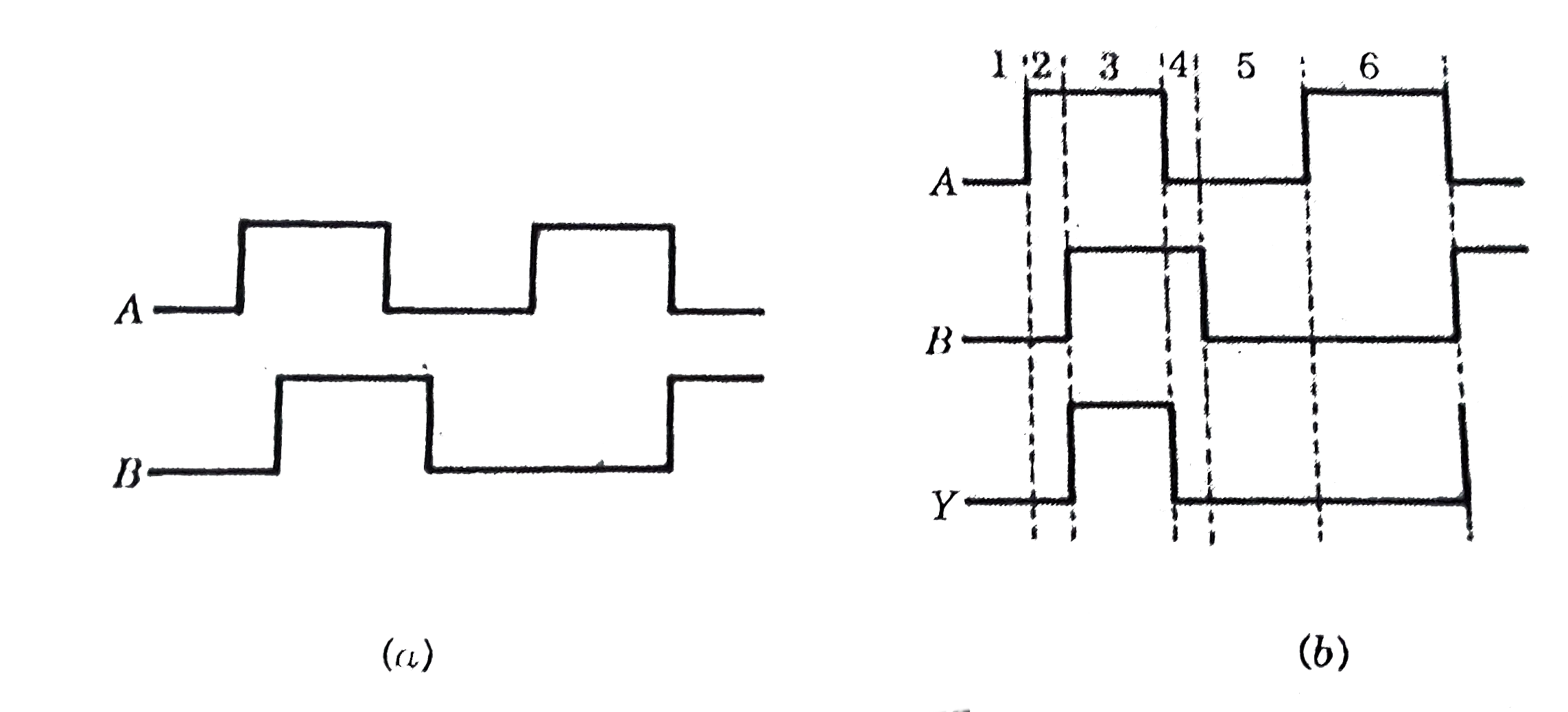
Two input waveforms A and B shown in fig (a) are applied to an AND gate.Write the output waveform.
 View Solution
Two sinusoidal waves with the same amplitude of 4.0mm and the same wavelength traveled together along a string that is stretched along an x axis, the resultant wave due to their interference was recorded on video tape. The curves in Fig. 16-20 represent the resultant wave in two freeze frames, first as the solid curve and then, 1.0 ms later, as the dotted curve. The grid lines along the x axis are 1.0 cm apart, and the string clements oscillated vertically (perpendicular to the x axis) by 6.0 mm as the resultant wave passed through them. That wave moved a distance d =4.20 cm to the right in the 1.0 ms time interval. Write equations for the two interfering waves and for their resultant wave.
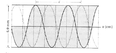
Figure 16-20 The resultant wave of two sinusoidal string wave traveling along an x axis is shown at two instants, between which the resultant wave travels distance d.View Solution
Knowledge Check
- Question 1 - Select One
In the given circuit as shown the two input waveform A and B are applied simultaneously. The resultant waveform Y is
 A
A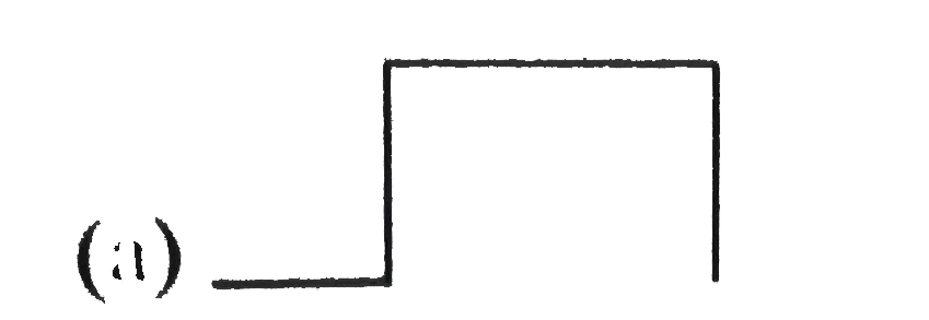 B
B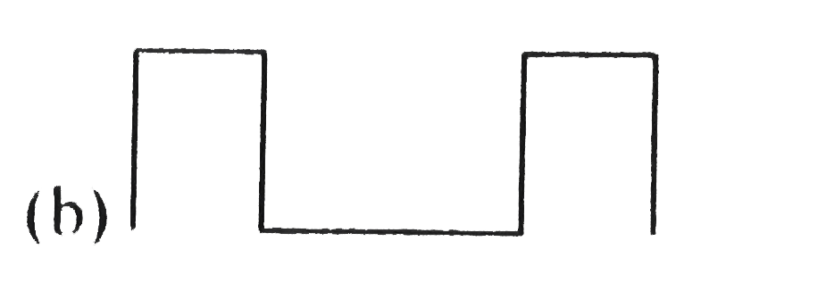 C
C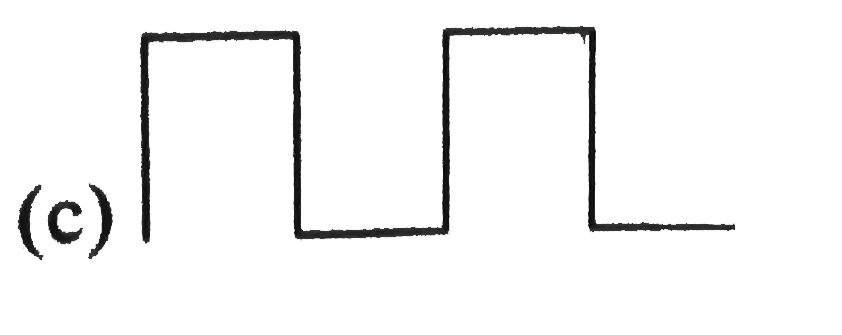 D
D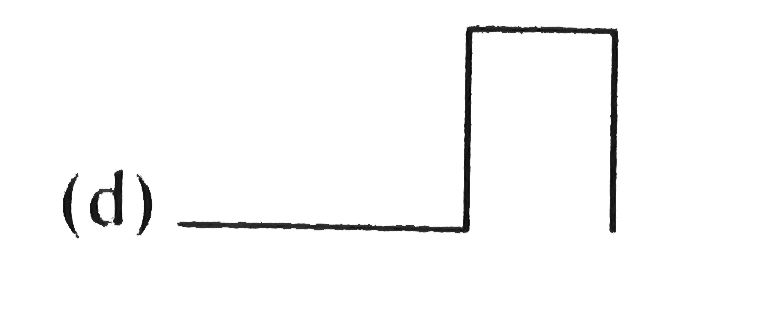
- Question 2 - Select One
The following figure shows a logic gate circuit with two inputs A and B and the output Y. The voltage waveforms of A,B and the output Y are as given
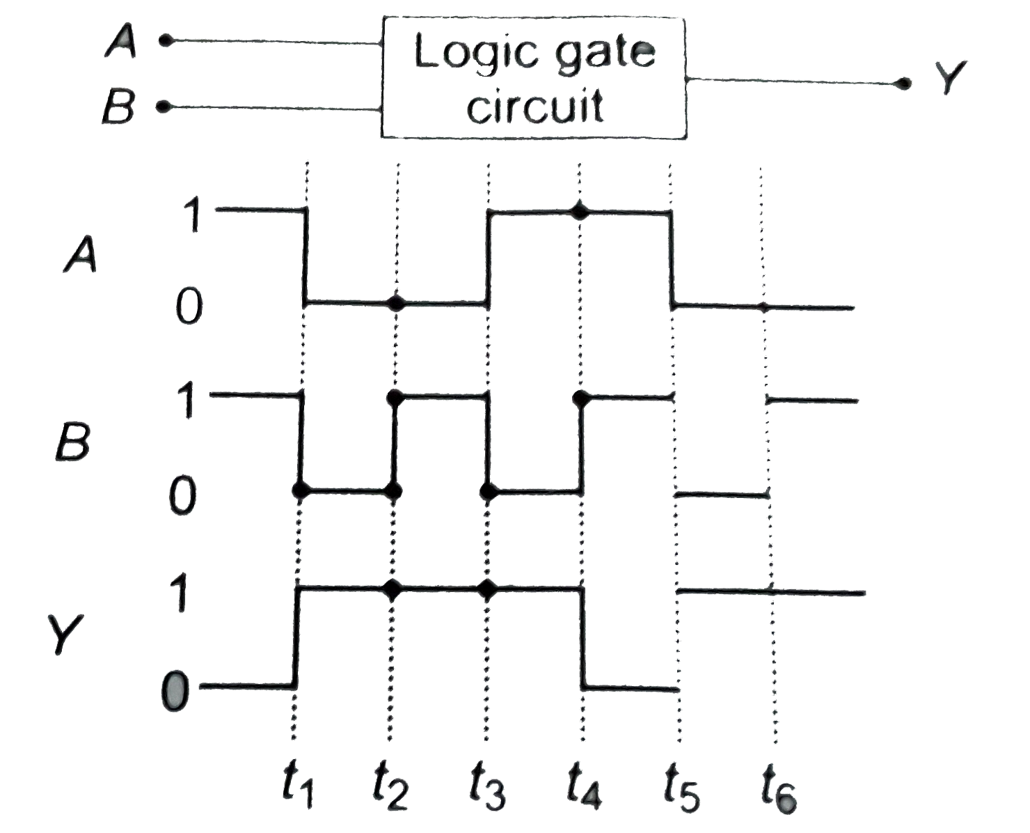 ANOR gateBOR gateCAND gateDNAND gate
 - Question 3 - Select One
The r.m.s. voltage of the wave form shown is
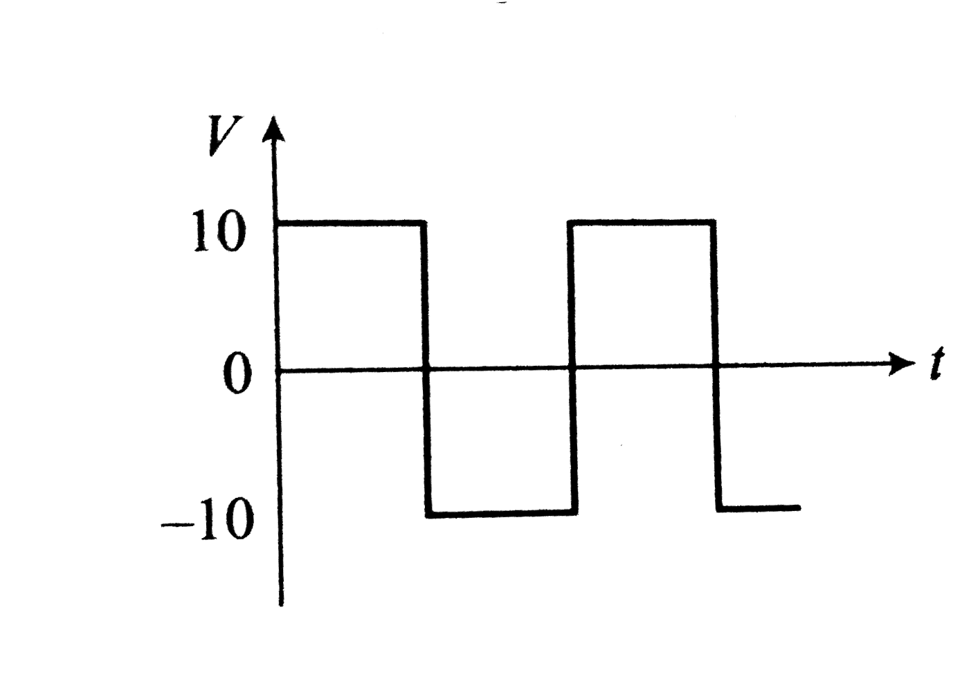 A10VB7VC6.63VDNone of these
The input wave form for NOT gate is shown in Fig.Draw the output wave form of this gate.
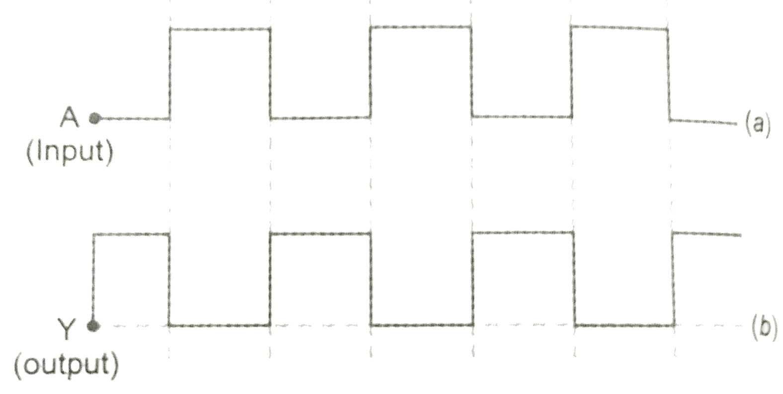 View Solution
The figure shows a logic circuit with two inputs A and B and the output C. The voltage wave forms across A,B and C are as given. The logic circuit gate is
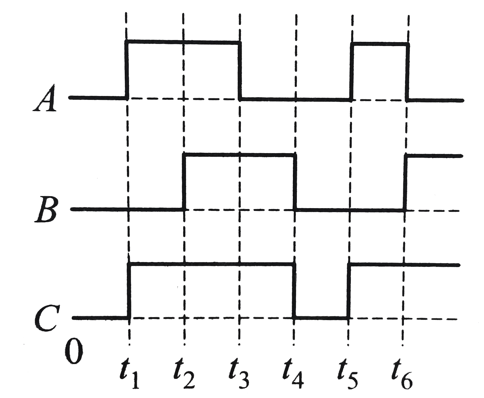 View Solution
The following figure shows a logic gate circuit with two inputs A and B and the output Y. The voltage waveforms of A,B and the output Y are as given
 View Solution
The following shows a logic gate circuit with two inputs A and B and the output C. The voltage waveforms of A, B and C are as shown below.
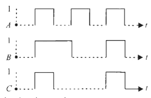
The logic circuit gate isView SolutionFig, shows a logic gate circuit with two input A and B and the output C. The voltage wave form of A, B and C are as shown in Fig.The logic gate circuit is
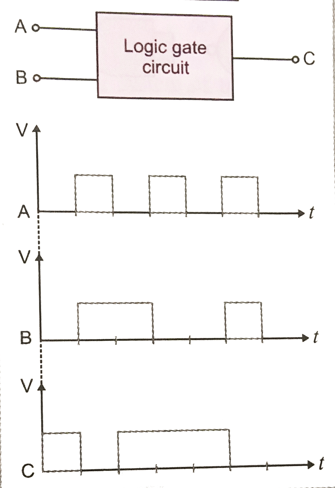 View Solution

