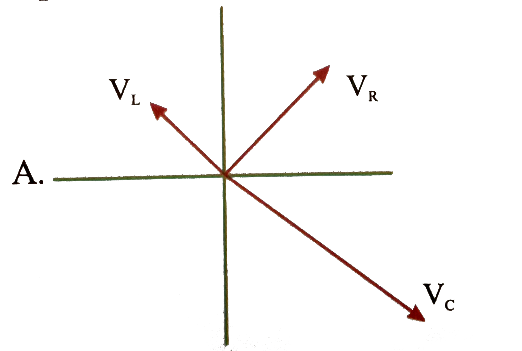
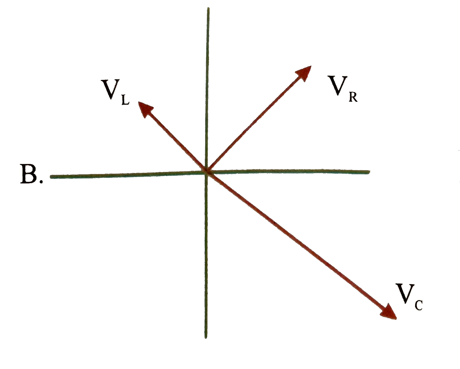
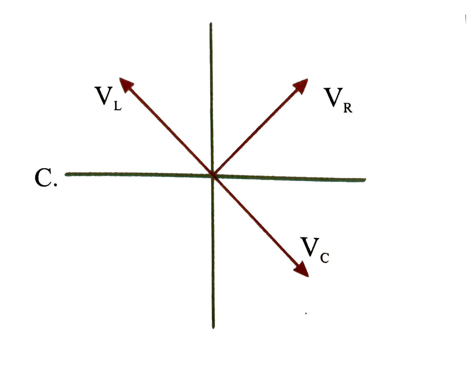
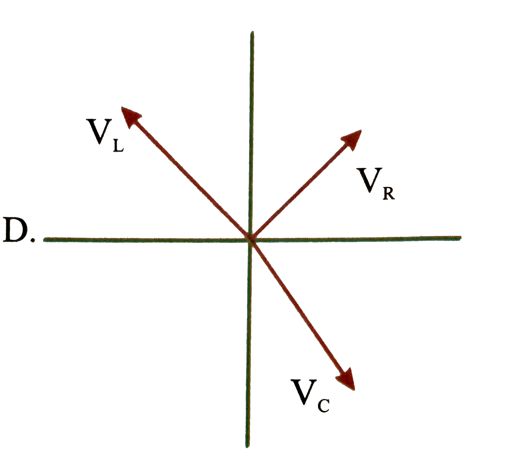
In the figure, which of the phasor diagrams represents RLC circuit driven at resonance?
A
B
C
D
Video Solution
Text Solution
The correct Answer is:C
At resonance, VL=VC also VL and VC are in opposite phase. A series LCR circuit containing a resistance of 120 has an angular resonance frequency. At resonance, voltage across resistance and inductance are 60V and 40V
|
Updated on:21/07/2023
Topper's Solved these Questions
- BOOK - NARAYNACHAPTER - ALTERNATING CURRENTEXERCISE - LEVEL - VI120videos
ALTERNATING CURRENT
- BOOK - NARAYNACHAPTER - ALTERNATING CURRENTEXERCISE - LEVEL - I (H.W)23videos
ALTERNATING CURRENT
- BOOK - NARAYNACHAPTER - ALTERNATING CURRENTEXERCISE - LEVEL - IV NCERT Based Questions15videos
ALTERNATING CURRENT
- BOOK - NARAYNACHAPTER - ATOMIC PHYSICSEXERCISE - LEVEL-II (H.W)14videos
ATOMIC PHYSICS
Similar Questions
Knowledge Check
- Question 1 - Select One
The series RLC circuit in resonance is called:
ASelector circuitBrejector circuitCamplifier circuitDoscillator circuit - Question 2 - Select One
In parallel resonant circuit, at resonance
Acurrent is maximum and impedance is maximumBcurrent is maximum and impedance is minimumCcurrent is minimum and impedance is maximumDcurrent is minimum and pmpedance is minimum - Question 3 - Select One
In series resonant circuit, at resonance,
AZ=√R2+(XL−XC)2BZ=XL−XCCZ=RDZ=XC
Draw the circuit diagram to represent the circuit shown below.
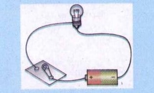 View Solution
Time Period || Phasor Diagram
View SolutionDraw the circuit diagram to represent the circuit shown infigure.
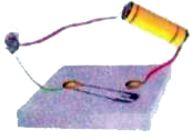 View Solution
Use a phasor diagram to represent the sine waves in the following Figure.
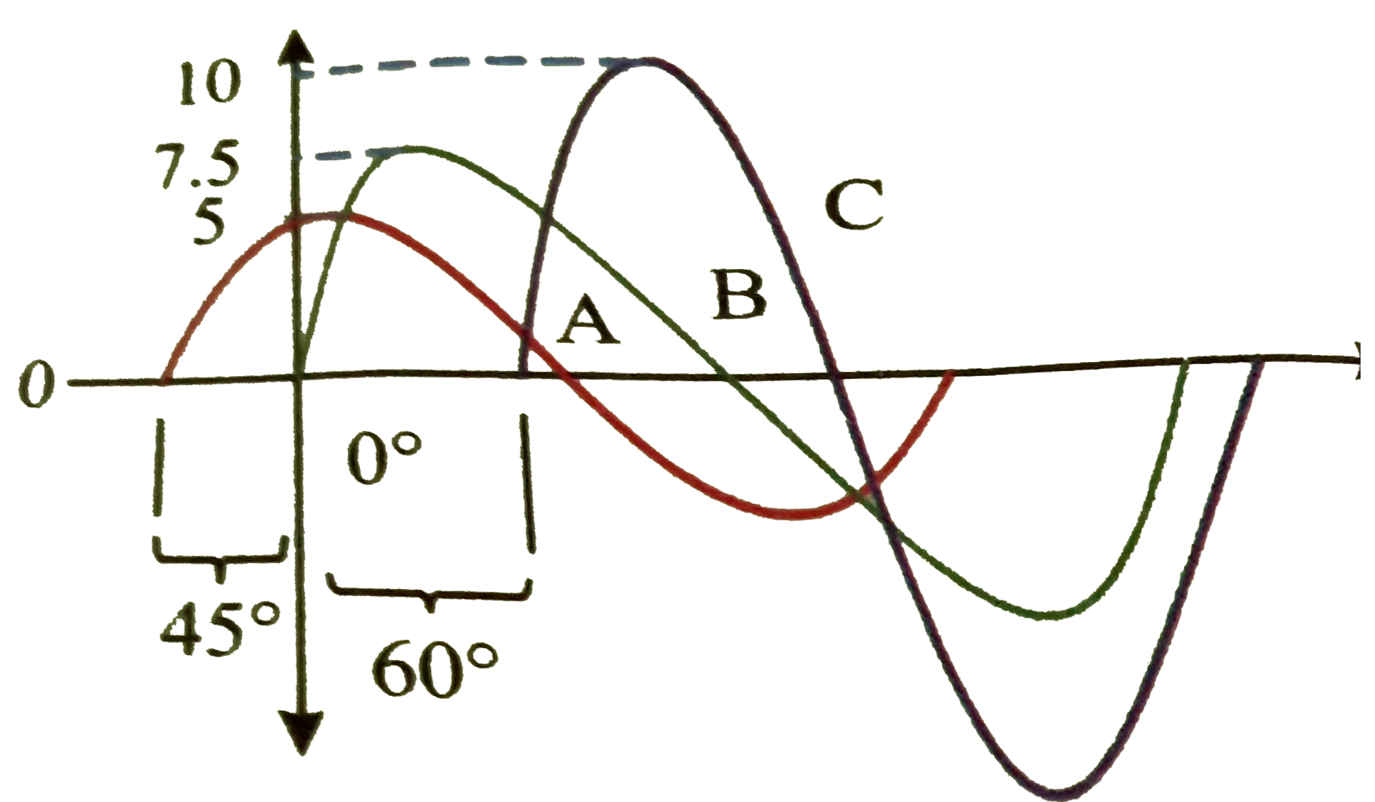 View Solution
In resonant circuit, at resonant frequency
View Solution
