A diode is a device that conducts in one direction only. Figure (a) shows the symbol for a diode. When terminal A is at higher potential than B, the diode conducts, it means current flows from A to B. No current flows if B is kept at higher potential. Find the potential difference between terminals C and D after the switch (S) is closed in the circuit shown in Figure (b).
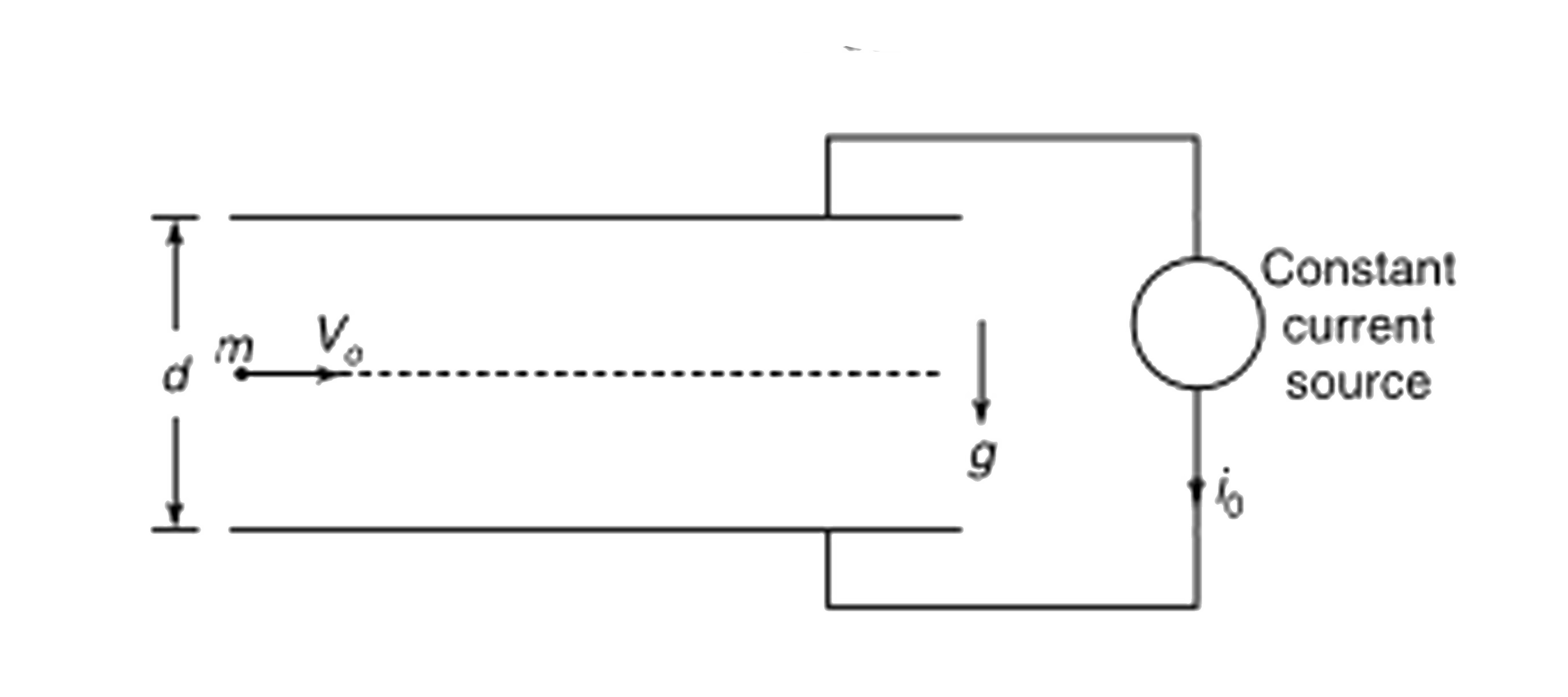
The correct Answer is:40 V
Step by step video, text & image solution for A diode is a device that conducts in one direction only. Figure (a) shows the symbol for a diode. When terminal A is at higher potential than B, the diode conducts, it means current flows from A to B. No current flows if B is kept at higher potential. Find the potential difference between terminals C and D after the switch (S) is closed in the circuit shown in Figure (b). by Physics experts to help you in doubts & scoring excellent marks in Class 12 exams.
Topper's Solved these Questions
Similar Questions
A resistance R and a capacitor having capaci- tance C are connected to an alternating source having emf v=V0sin(ωt).It is given that ω=1√3RC
(a) Plot the variation of power supplied by the source as a function of time. Mark the maximum and minimum values of power in the graph.
(b) How does the plot change if capacitor is removed and only R remains connected to the source?
(c) Plot the graph when only C remains connected to source and R is removed.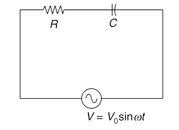 01:50View Solution
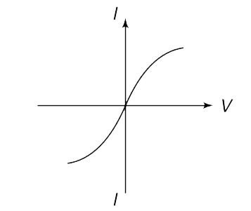
The current-voltage graph for a resistor is as shown in the figure. Is it right to say that resistance decreases as the current through it increases ?
 04:03View Solution
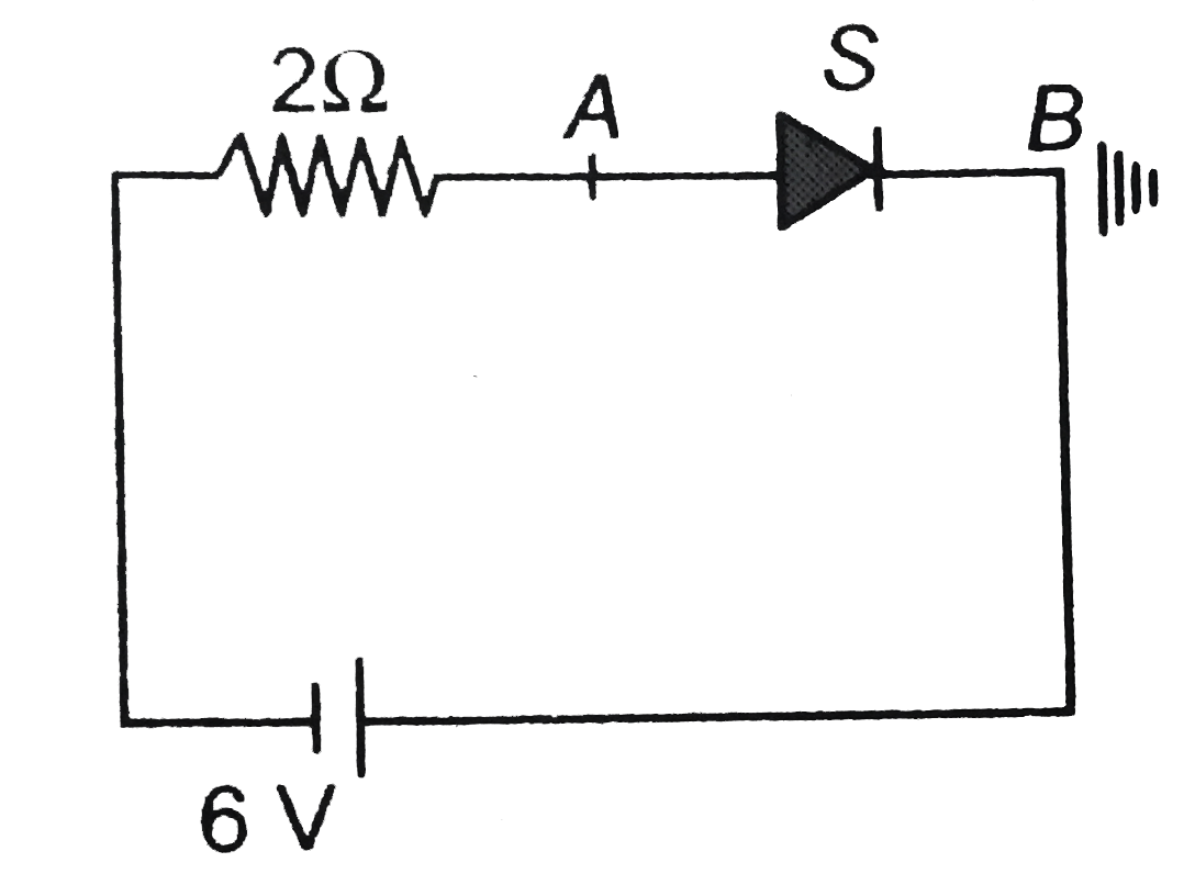
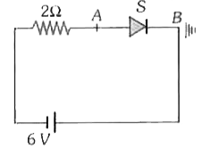
The diode shown in the circuit is a silicon diode. The potential difference between the points A and B will be
 05:37View Solution
Two junction diodes, one of germanium (Ge) and other of silicon (Si) are connected as shown in fig to a battery of 12 V and a load resistance 10 kOmega . The germanium diode conducts at 0.3 V and silicon diode at 0.7 V . When current flows in the circuit, the potential of terminal Y will be .
10:59View Solution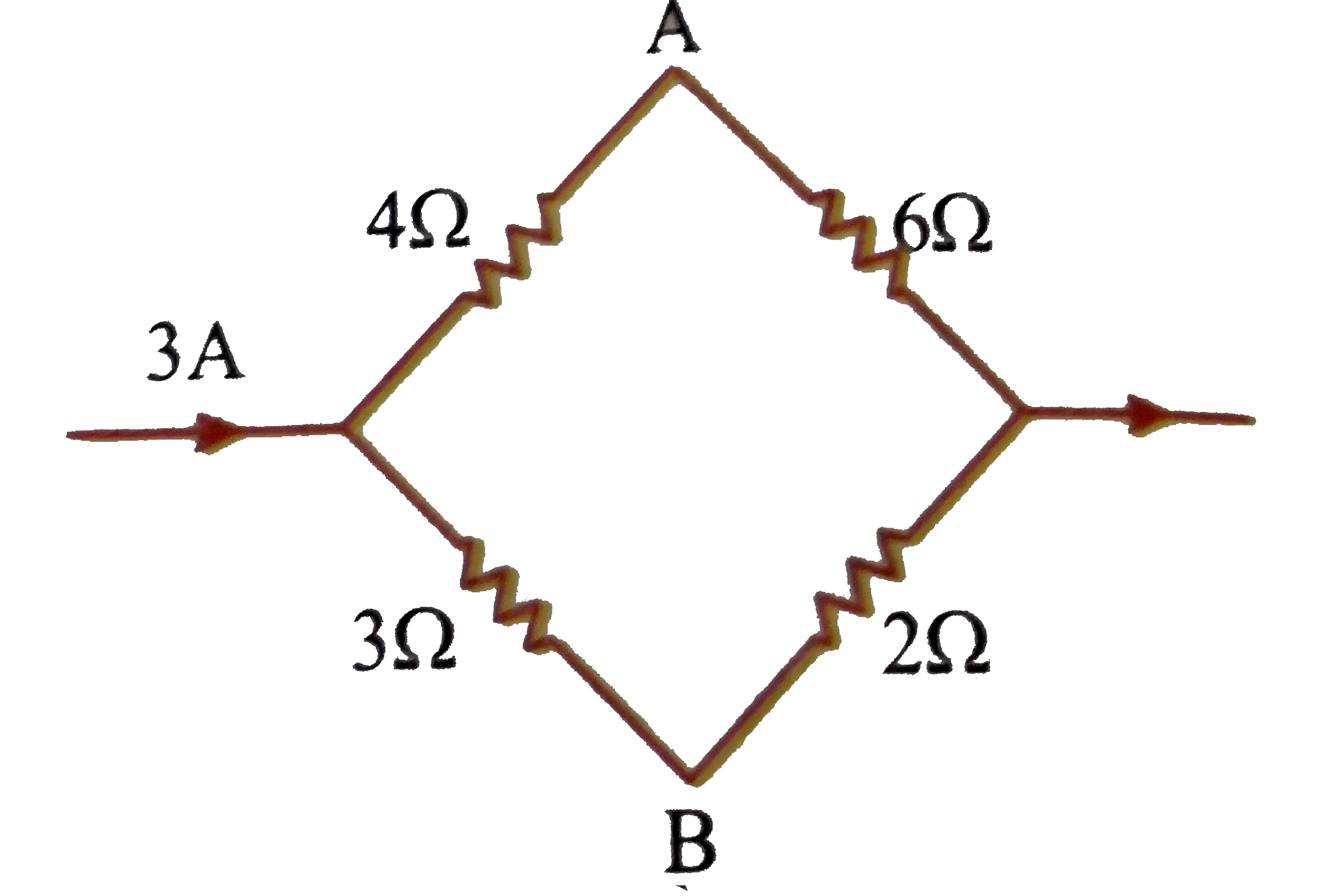
A current of 3A flows in a circuit shown in the figure. The potential difference between A and b is01:50View SolutionIn the circuit shown in figure points a, b and c are maintained at constant (but may be different) potentials. When a resistance is connected between a and b no current flows through it, when the same resistance is connected between b and c current flows from c to b.
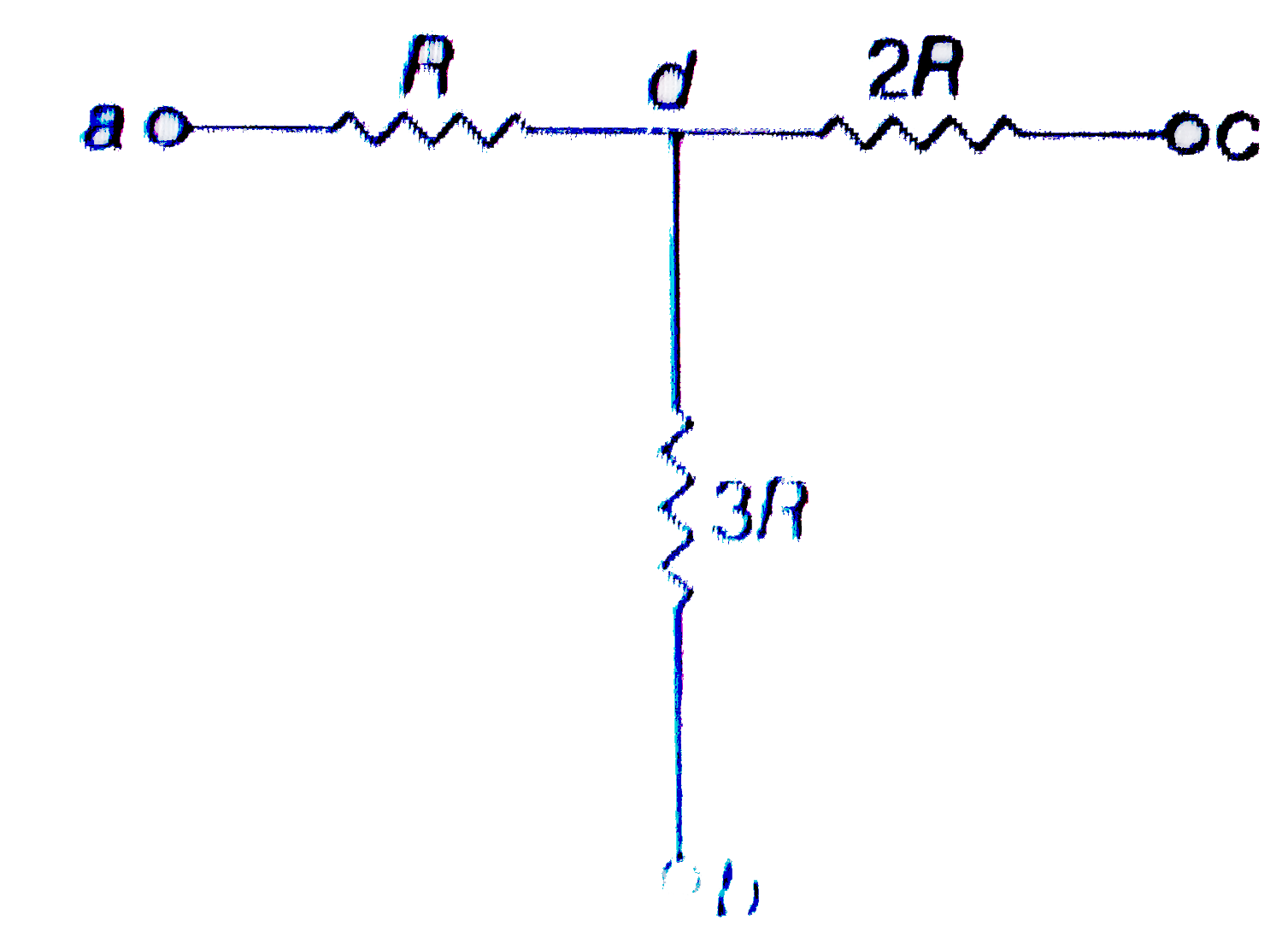
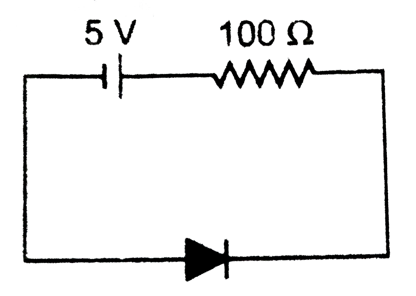
When only three resistance shown in figure are in the circuit03:36View SolutionFind the current through the circuit and the potential difference across the diode shown in fig. The drift current for the diode is 20muA
02:08View SolutionIn the circuit shown in figure , the diode is ideal The potential difference between A and B is
02:47View SolutionIn the circuit shown if current for the diode is 20 muA , the potential difference across the diode is
04:07View Solutionचित्र में प्रदर्शित डायोड में बहने वाली अपवाह धारा 20μA है। परिपथ में नेट धारा तथा डायोड के सिरों का विभवान्तर ज्ञात कीजिये।
 02:49View Solution
Find the equivalent resistance of the network shown in figure between point A and B when the p-n junction diode is ideal and:
(i) A is at higher potential.
(ii) B is at higher potential
 03:06View Solution
एक सिलिकॉन डायोड परिपथ चित्र में दिखाया गया है। बिन्दु A एवं B के बीच विभवान्तर होगा
 View Solution
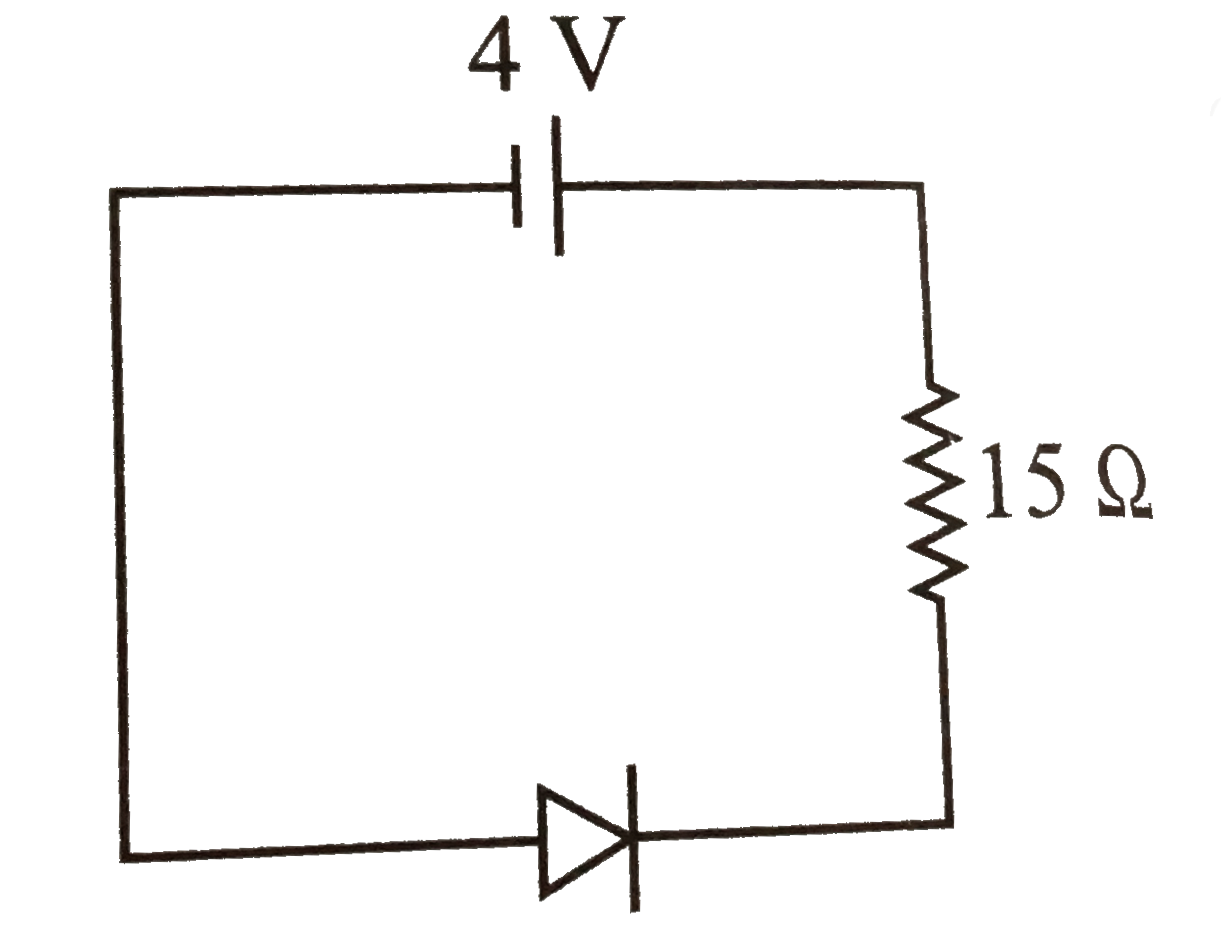
In the circuit shown if current for the diode is 20μA, the potential difference across the diode is02:46View SolutionTwo junction diodes, one of germanium (Ge) and other of silicon (Si) are connected as shown in fig to a battery of 12V and a load resistance 10kOmega . The germanium diode conducts at 0.3V and silicon diode at 0.7V. When current flows in the circuit, the potential of terminal Y will be
02:54View SolutionThe diode shown in the circuit is a silicon diode. The potential difference between the points A and B will be
02:52View Solution

