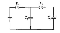
How does the total energy stored in the capacitors in the circuit shown in the figure change when first switch K1 is closed (process-1) and then switch K2 is also closed (process-2), Assume that all capacitor were initially uncharged?
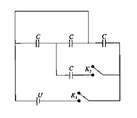
Increases in process-1
Increases in process-2
Decreases in process-2
Magnitude of change in process -2 is less than that in process-1
The correct Answer is:A, B, D
Equivalent circuit
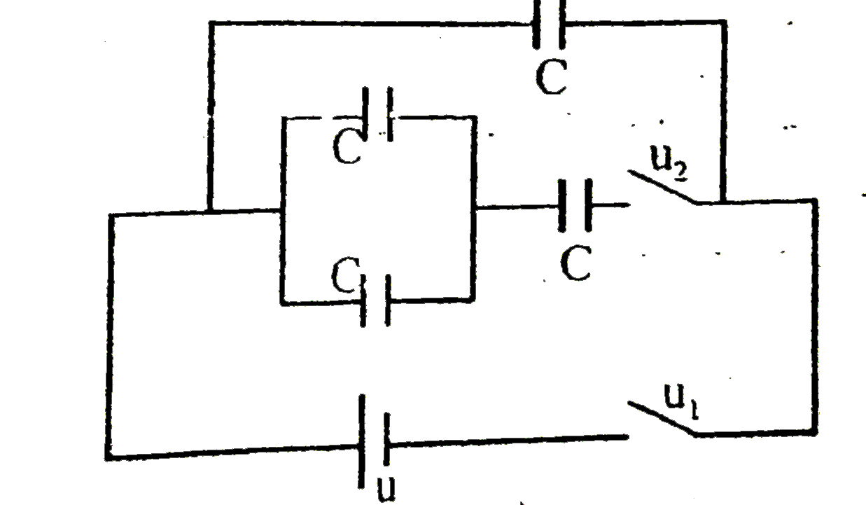
equivalent capacitance =5C3
When k2 is closed no increasing in energy
when k1 is closed E=12cqV2=125C3V2=5CV26
Topper's Solved these Questions
- BOOK - BANSALCHAPTER - MASTER PRACTICE PROBLEMEXERCISE - Subjective107videos
MASTER PRACTICE PROBLEM
- BOOK - BANSALCHAPTER - MASTER PRACTICE PROBLEMEXERCISE - Additional topic70videos
MASTER PRACTICE PROBLEM
- BOOK - BANSALCHAPTER - MASTER PRACTICE PROBLEMEXERCISE - Reasoning75videos
MASTER PRACTICE PROBLEM
- BOOK - BANSALCHAPTER - FLUID MECHANICSEXERCISE - PYQS AIEEE10videos
FLUID MECHANICS
- BOOK - BANSALCHAPTER - SEMICONDUCTORSEXERCISE - CBSE Question32videos
SEMICONDUCTORS
Similar Questions
Knowledge Check
- Question 1 - Select One
In the circuit shown in fig. when the switch is closed, the capacitor charges with a time constant
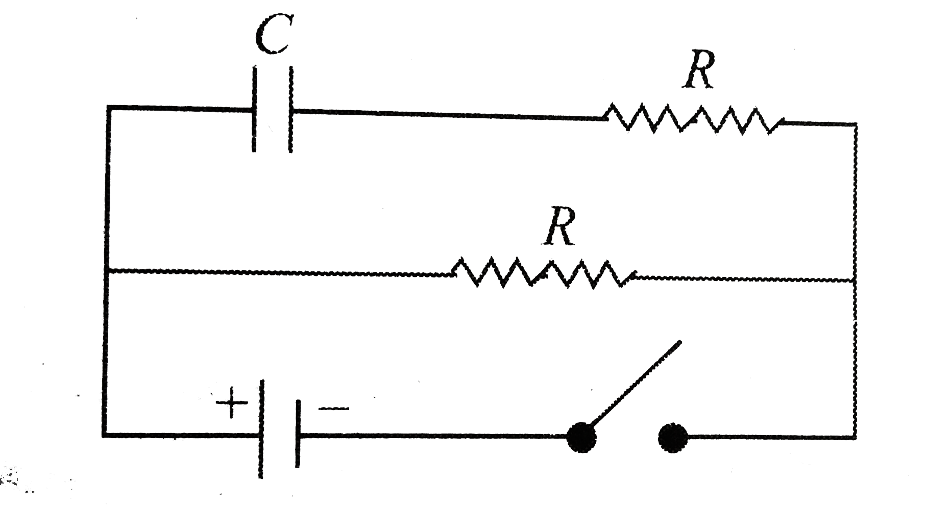 ARCB2 RCC12RCDRC log2
 - Question 2 - Select One
In the circuit shown in the figure, if switches S1 and S2 have been closed for a long time, then charge on the capacitor.
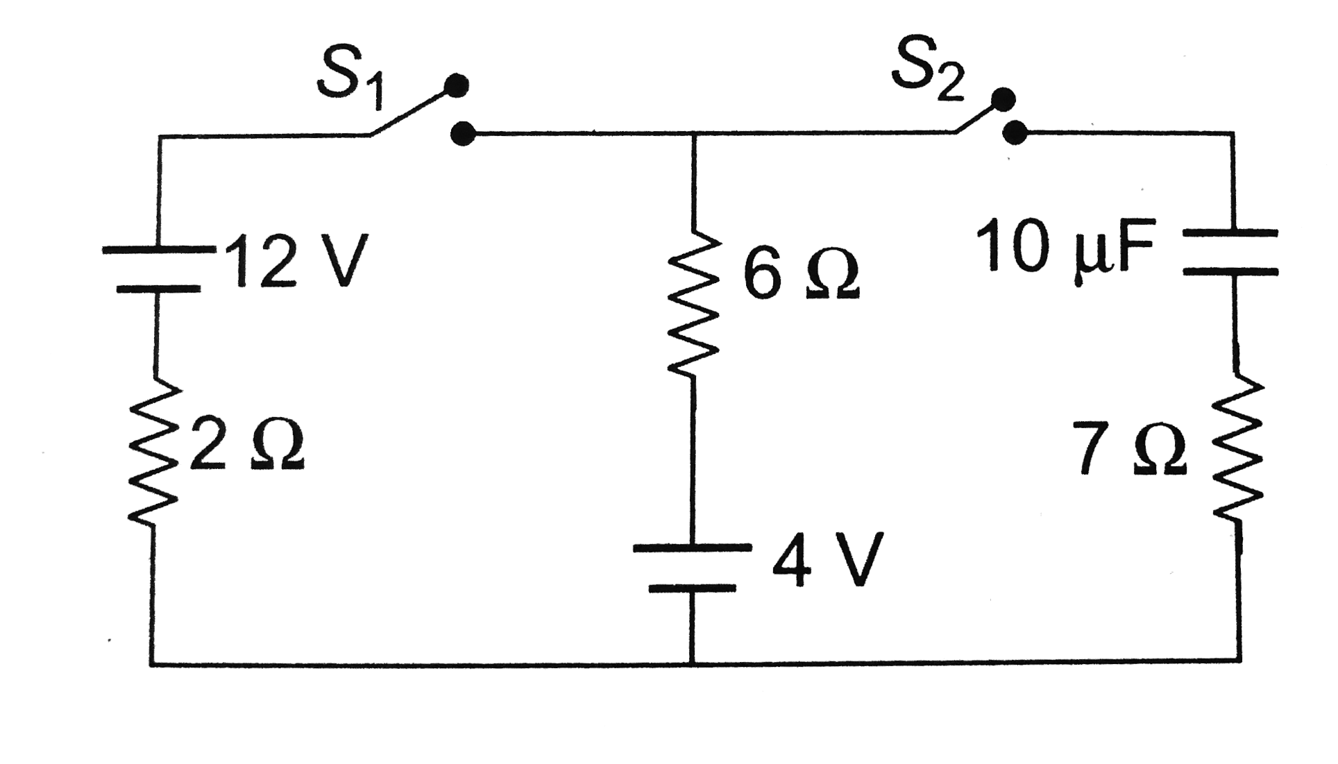 Ais 100μCBincreases to 200μC if one third of the gap of the capacitor's plates is filled with a dielectric (K=2) of same areaCboth (a) and (b) aboveDcharge on the capacitor remains unchanged if one third of the gap of the capacitor's plates is filled with a dielectric (K=2) of same area.
 - Question 3 - Select One
The two capacitors in the circuit shown in figure are initially uncharged and then connected as shown and switch is closed. What is the potential difference across 3μF capacitor?
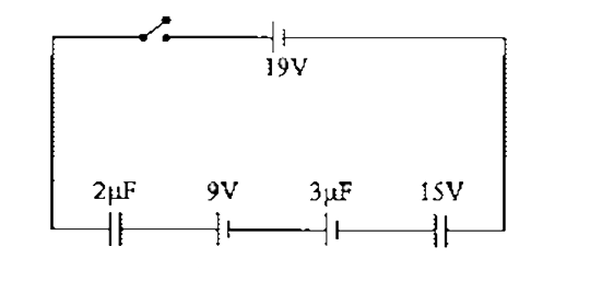 A30VB10VC25VDNone of these
In the given circuit, the initial charges on the capacitors are shown in the figure. The charge flown through the switches S1andS2 respectively after closing the switches are
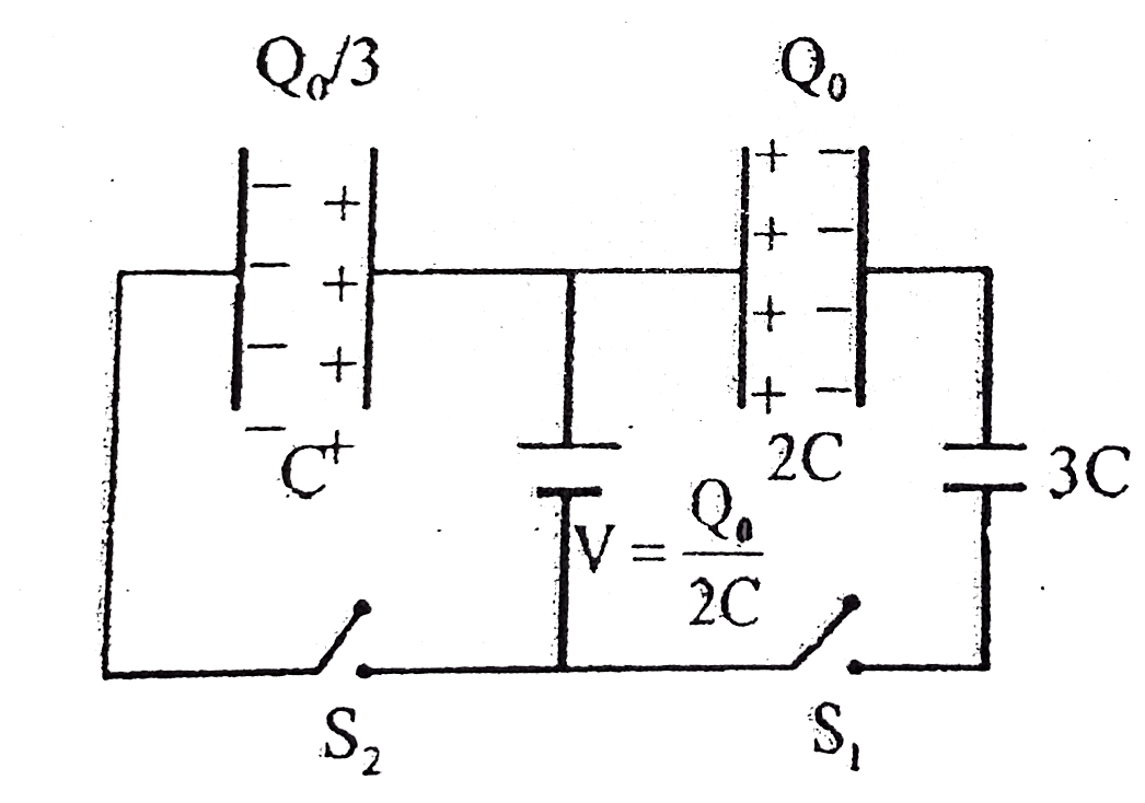 View Solution
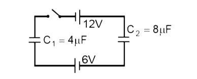
In the circuit shown initially C1,C2are uncharged. After closing the switch
 View Solution
In the circuit shown in the figure, the capacitor C is charged to a potential Vo. The heat generated in the circuit when the switch S is closed, is
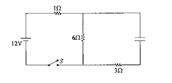
View SolutionIn the circuit shown in figure-3.348 when the switch is closed, the initial current through the 1Ω resistor just after closing the switch is
 View Solution
In the circuit shown in figure initially the switch is opened. The switch is closed now.
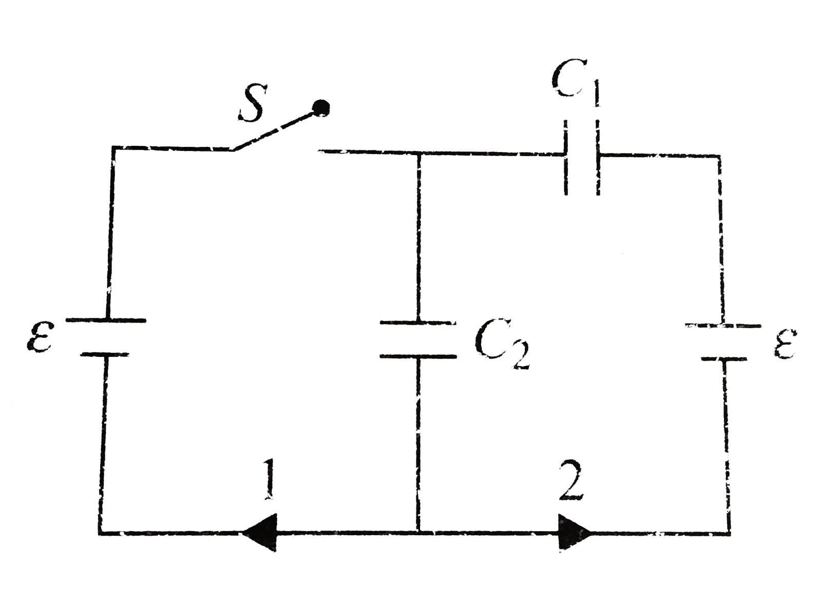
The charge that will flow in direction 1 isView Solution


