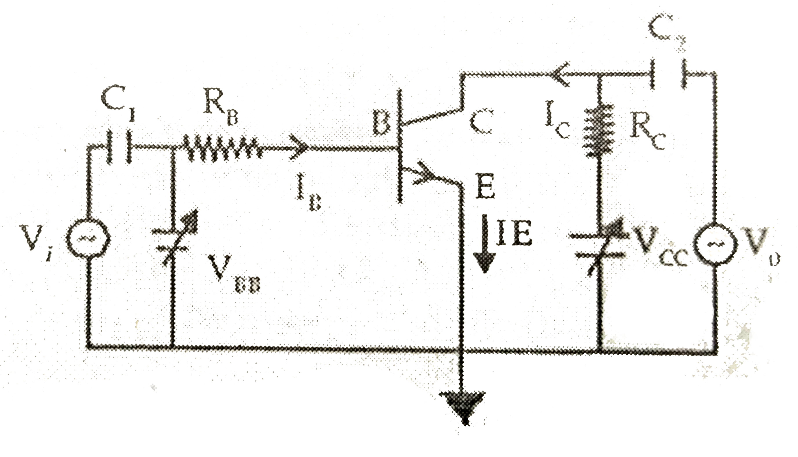
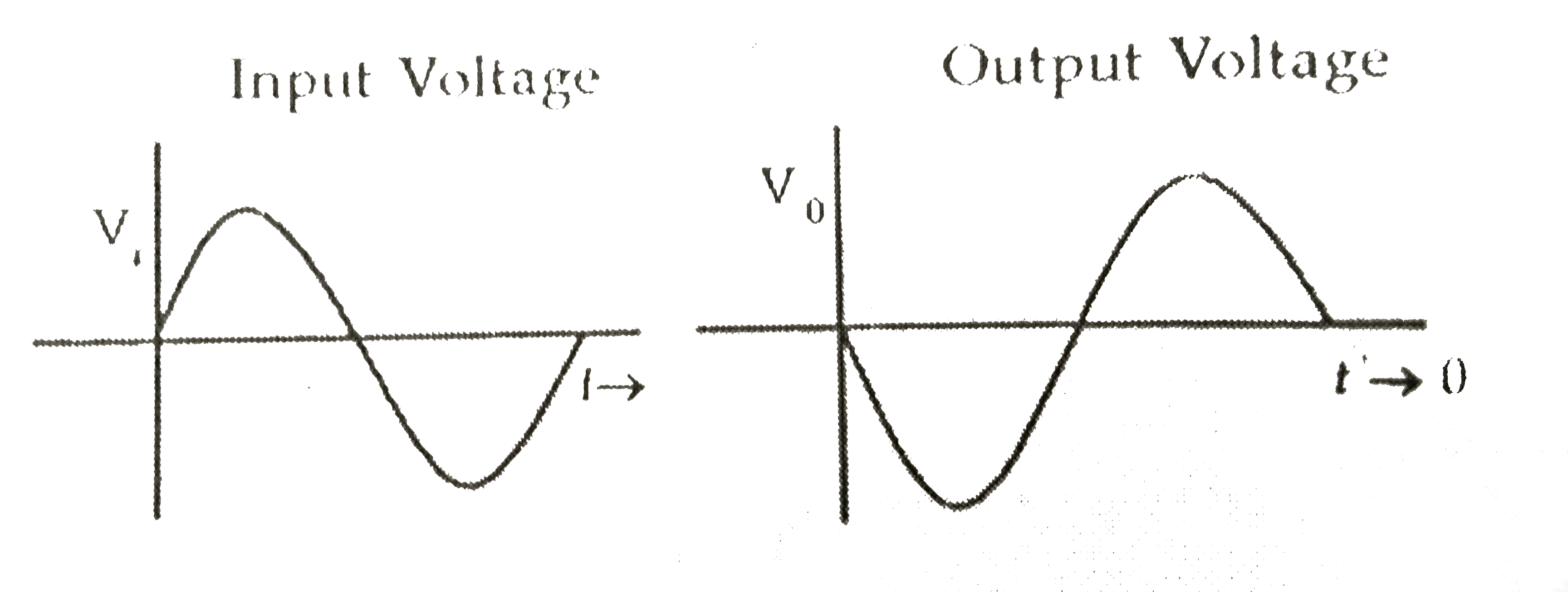
Draw a labelled circuit diagram of n - p - n germanium transistor in common emitter configuration. Explain briegfly , how this transistor is used as a voltage amplifier.
Transistor as an amplifier is based on the principle that a weak input signal given to a base region produces an amplified out signal in the collector region.
The input voltage signal is connected between base and emitter through a capacitor which filters d .c voltage from going towards a . c input source . The output is taken from the collector resistance . The capacitor filters the dc voltage from the output signal .
Applying kirchhoff 's second law on input loop
. . . (i)
Applying Kirchhoff 's second law on output loop
. . . (ii)
From equation (i) , . . . (iii)
Subtracting (i) from (iii) ,

Change in collector current . . . (iv)
Where ,
From (ii) and (iv) , Voltage gain

Negative sign shows that input and output signals differ in phase by radian (out of phase).
Topper's Solved these Questions
- XII BOARDSBOOK - XII BOARDS PREVIOUS YEARCHAPTER - XII BOARDSEXERCISE - SECTION - D
6 Videos
- XII BOARDSBOOK - XII BOARDS PREVIOUS YEARCHAPTER - XII BOARDSEXERCISE - SECTION - E
6 Videos
- XII BOARDSBOOK - XII BOARDS PREVIOUS YEARCHAPTER - XII BOARDSEXERCISE - [SET -III, OUTSIDE DELHI]
5 Videos
- SAMPLE PAPER 2019BOOK - XII BOARDS PREVIOUS YEARCHAPTER - SAMPLE PAPER 2019EXERCISE - SECTION D
6 Videos
Similar Questions
Draw a labelled circuit diagram of n - p - n germanium transistor in common emitter configuration. Explain briefly, how this transistor is used as a voltage amplifier.
View SolutionDraw a labelled circuit diagram of a transistor acting as a common emitter amplifier. What is meant by phase reversal?
View Solution
Knowledge Check
A transistor is used in the common emitter mode as an amplifier . Then
Athe base-emitter junction is reverse biasedBbase-collected junction is reverse biasedCthe input single is connected in series with the voltage applied to bias the base emitter junction.Dall of theseIf a transistor is used in common -emitter mode as an amplifier,then
Athe base -collector junction is forward biasedBthe base -emitter junction is reverse biasedCthe input signal is connected in series with the voltage applied to the base -emitter junctionDthe input signal is connected in series with the voltage applied to the base -collector junctionIn the following common emitter configuration, and n-p-n transistor with current gain β=100 is used. The output voltage of the amplifier will be
 A10 mVB0.1 VC1.0 VD10 V
With the help of a labelled circuit diagram, explain how an n-p-n transistor can be used as an amplifier in common-emitter configuration. Explain how the input and output voltages are out of phase by 180 for a common-emitter transistor amplifier.
View SolutionWith a neat labelled diagram, explain the actionn of npn transistor in common base configuration
View SolutionWith the help of a labelled circuit diagram, explain how an n-p-n transistor can be used as an amplifier in common-emitter configuration. Explain how the input and output voltages are out of phase by 1800 for a common-emitter transistor amplifier.
View SolutionDraw the labelled circuit diagram of a common-emitter transistor amplifier : Explain clearly how the input and output signals are in opposite phase.
View SolutionDraw a circuit diagram of n−p transistor amplifier in CE configuration. Under what condition does the transistor acts as an amplifier?
View Solution
