The potential difference (Vp−VQ) between the points P and Q in the part of a circuit as shown in figure is _PHY_E05_110_Q01.png)
A
6V
B
9V
C
−12V
D
12V
Video Solution
|
Answer
Step by step video & image solution for The potential difference (V_p-V_Q) between the points P and Q in the part of a circuit as shown in figure is by Physics experts to help you in doubts & scoring excellent marks in Class 12 exams.
Updated on:21/07/2023Topper's Solved these Questions
Similar Questions
Knowledge Check
The potential difference (VA−VB) between the point A and B in the given figure is :
 A+6VB+9VC−3VD−8V
The potential difference between the points P and Q in the adjoining circuit will be-
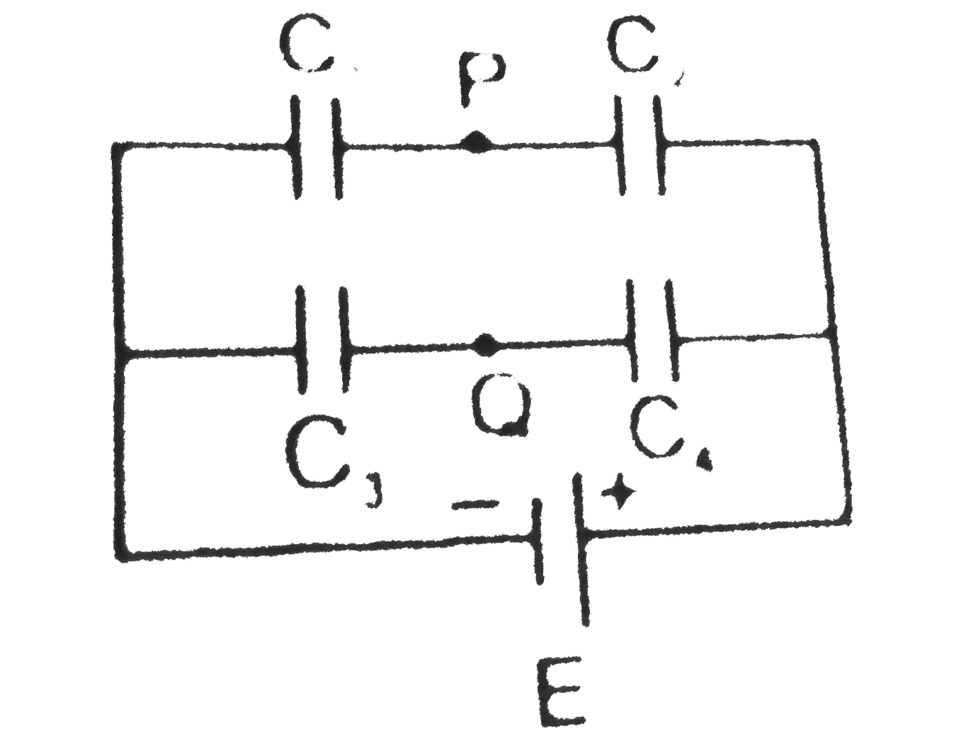 A(C1C4−C2C3)E(C1+C3)(C2+C4)BC2C3EC1C2(C3+C4)CC2C3−C1C4E(C1+C2)(C3+C4)D(C2C3−C1C4)E(C1+C2+C3+C4)
The potential difference (VA−VB) between the point A and B as shown in the figure is
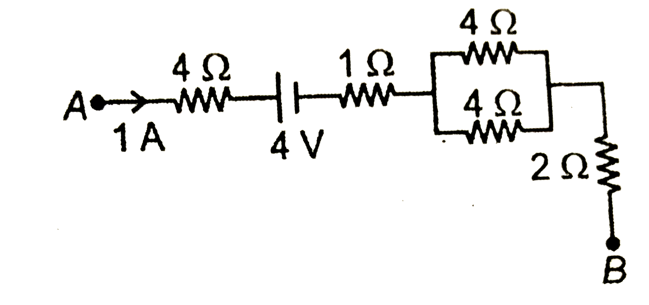 A9VB8VC15VD13V
The net resistance between points P and Q in the circuit shown in figure is
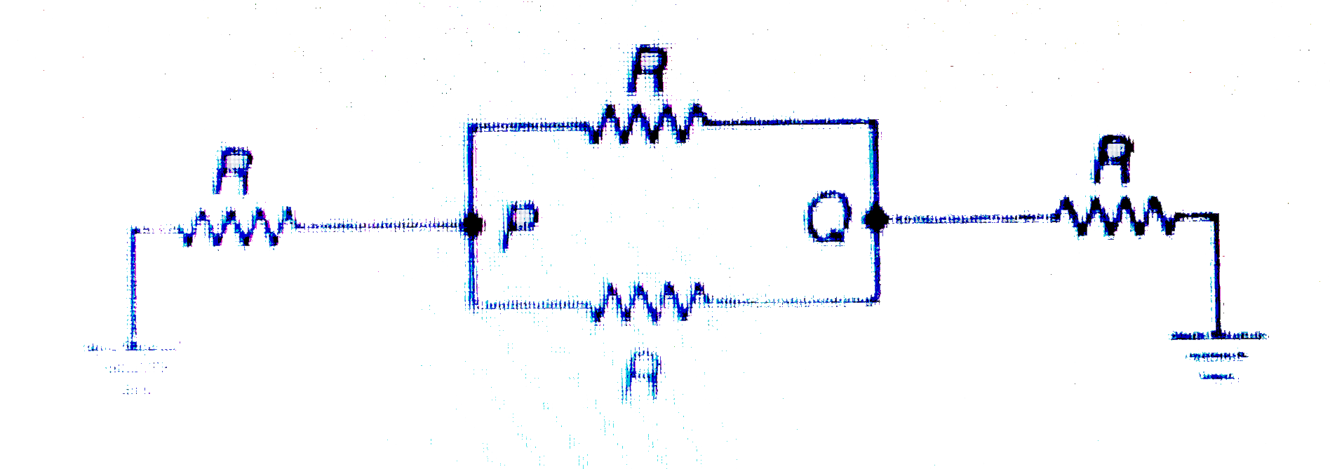
View SolutionThe potential difference VA−VB between points A and B for the circuit segment shown in figure at the given instant is
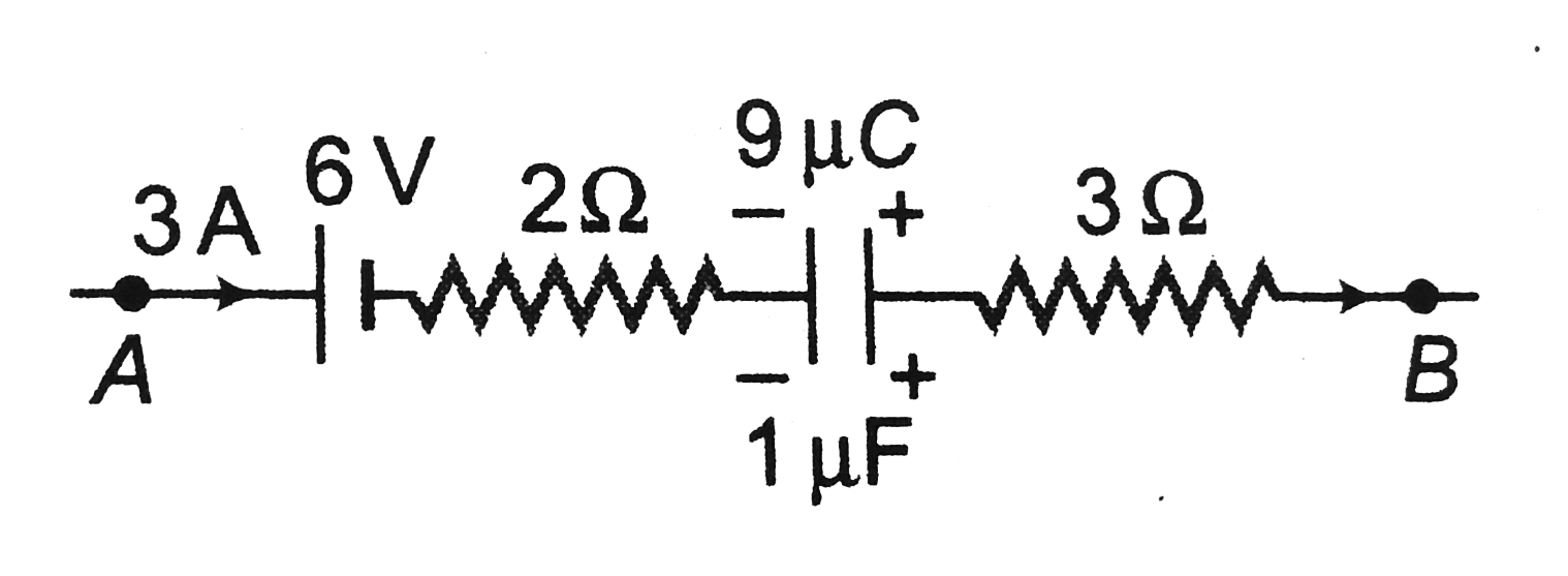
View SolutionPotential difference between the points P and Q in the electric circuit shown is

View SolutionWhat is the potential difference between the points A and B in the circuit diagram shown in figure ?
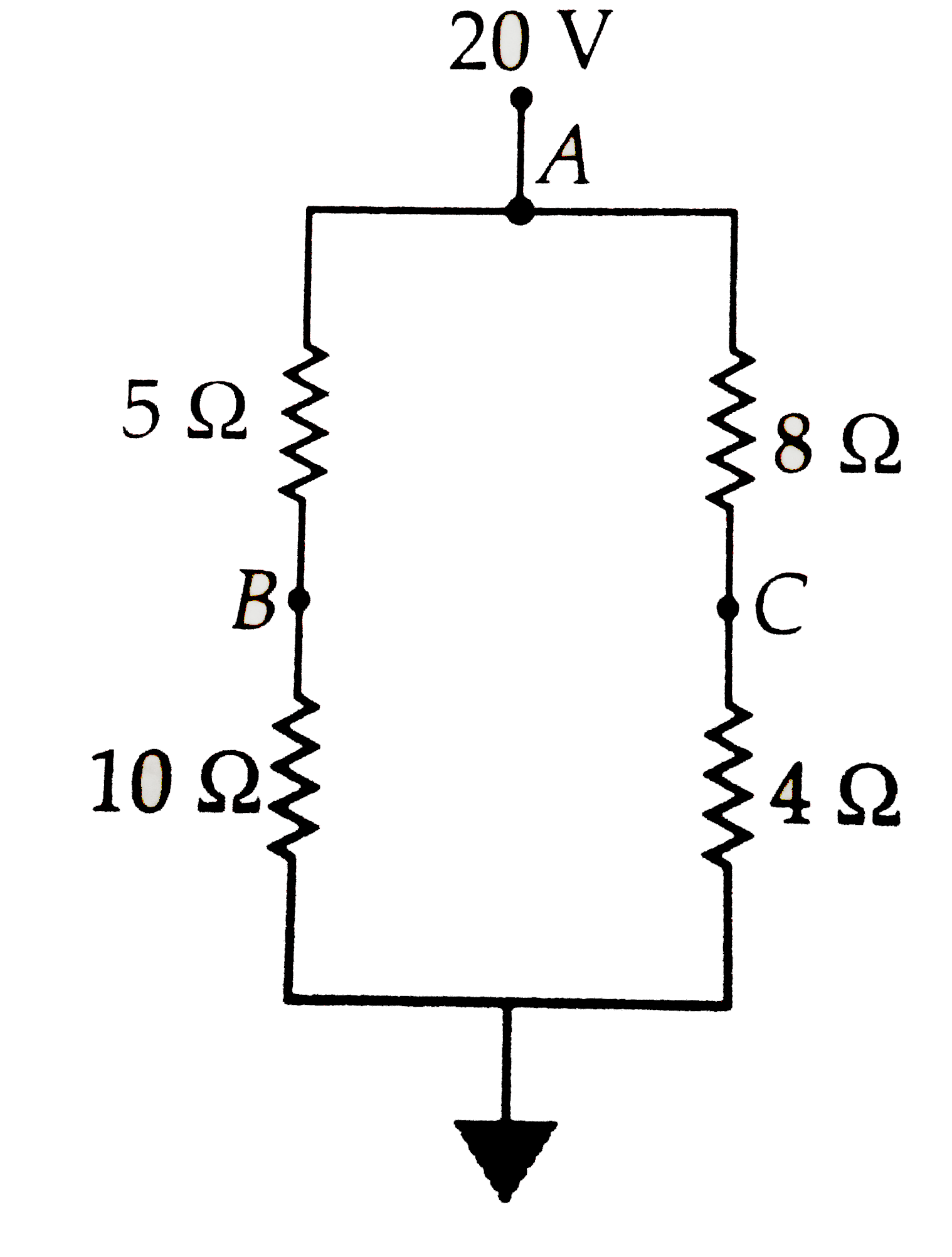
View SolutionThe potential difference between the points A and B in the following circuit shown in the figure:-
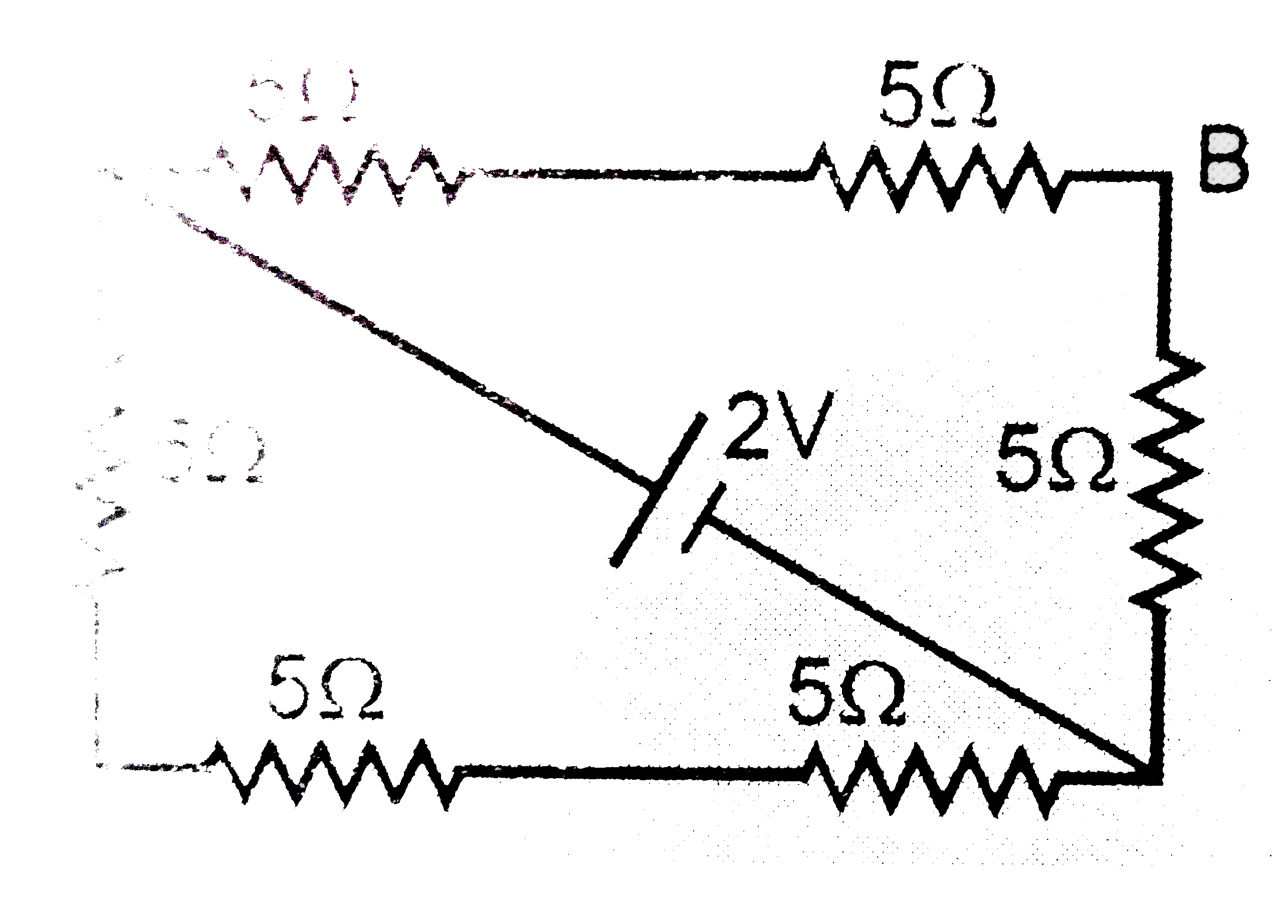
View Solution


