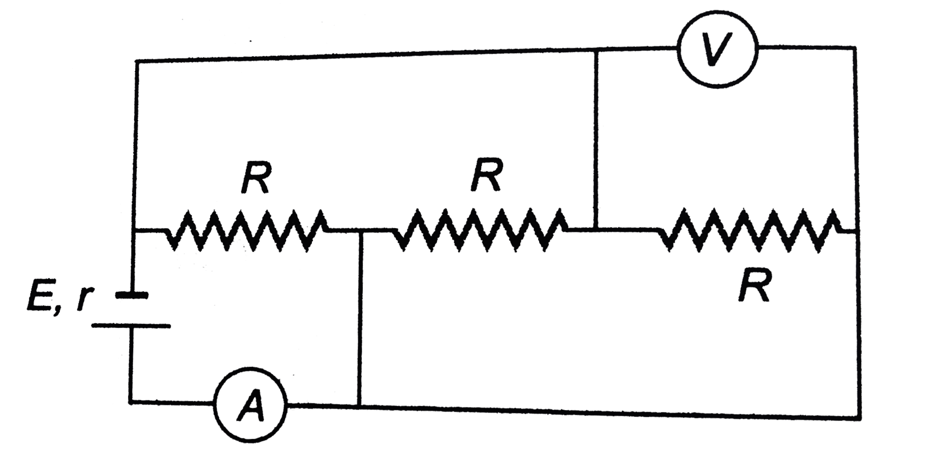
In the circuit shown, A and V are ideal ammeter and voltmeter respectively. Reading of the voltmeter will beSolution in Marathi
2 V
1 V
0.5 V
zero
Step by step video & image solution for In the circuit shown, A and V are ideal ammeter and voltmeter respectively. Reading of the voltmeter will be by Physics experts to help you in doubts & scoring excellent marks in Class 12 exams.
Similar Questions
A circuit is shown in the figure. The ratio of readings of ideal voltmeter to reading of ideal ammeter is
03:00View SolutionThe reading of ammeter and voltmeter in the circuit shown in the diagram are 4 A and 20 V respectively. The meter is ideal if R is:
02:45View SolutionAssertion : In the circuit shown in figure ammeter and voltmeter are non-ideal when positions of ammeter and voltmeter are changed, reading of ammeter will increase while of voltmeter will decrease. Reason : Resistance of an ideal ammeter is zero while that of an ideal voltmeter is infinite.
03:11View SolutionIn the circuit shown in figure ammeter and voltmeter are ideal. If E=4 V,R=9Omega and r=1Omega then readings of ammeter and voltmeter are
04:12View SolutionIn the circuit shown, A and V are ideal ammeter and voltmeter respectively. Reading of the voltmeter will be
01:11View SolutionIn the circuit shown in figure ammeter and voltmeter are ideal. If E=4V,R=9Ω and r=1Ω then readings of ammeter and voltmeter are
 03:45View Solution
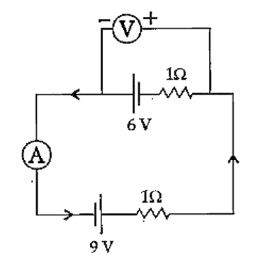
In the following circuit, determine the reading of ideal voltmeter (V) and ideal ammeter (A).
 03:56View Solution

