In figure C1=C5=8.4μF and C2=C3=C4=4.2μF.The applied potential is Vab=220V
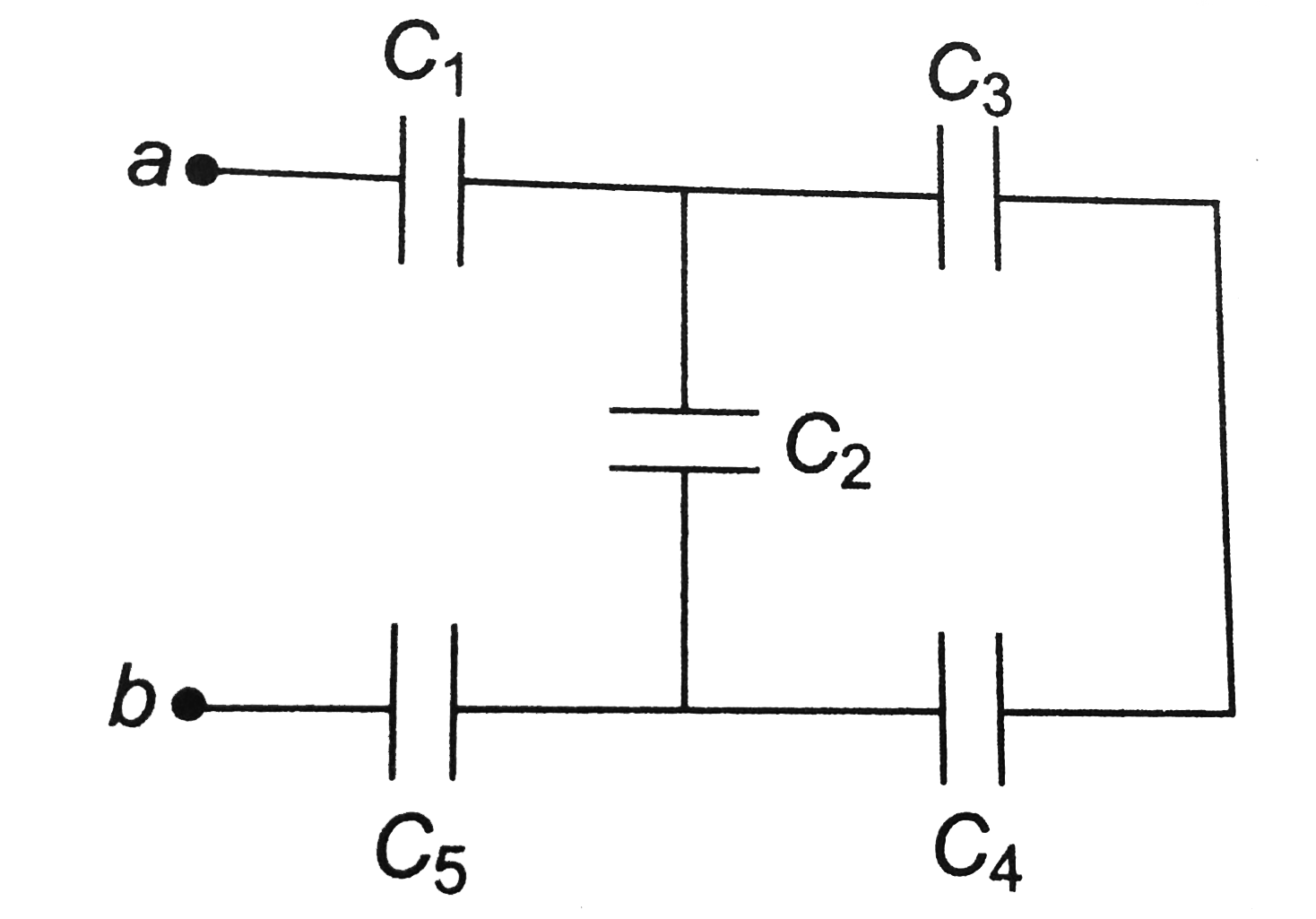
(a) What is the equivalent capacitance of the network between points a and b?
(b) Calculate the charge on each capacitor and the potential difference across each capacitor.
Video Solution
Text Solution
The correct Answer is:A
a. Simple series and paralle grouping of capacitor.
b. qnet=CnetV
=(2.5×10⁻⁶)(220)
=5.5×10⁻⁴C
C1,C5 and equivalent of other three capacitors are in series. Hence, charges across them are same
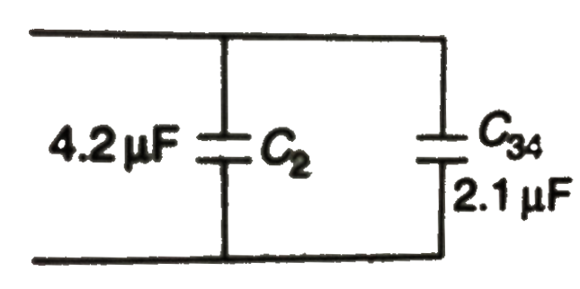
qtotal will distribute between C2 and C34 in direct ratio of capacitance.
∴q2q34=4.22.1=21
∴q2=23(5.5×10⁴)=3.7×10I−4C
q32=13(5.5×10⁻⁴)=1.8×10⁻⁴C
for finding PD across any capacitor use the equation
C=qV
|
Topper's Solved these Questions
- CAPACITORSBOOK - DC PANDEY ENGLISHCHAPTER - CAPACITORSEXERCISE - OBJECTIVE_TYPE
1 Video
- CAPACITORSBOOK - DC PANDEY ENGLISHCHAPTER - CAPACITORSEXERCISE - OBJECTIVE_TYPE
1 Video
- ATOMSBOOK - DC PANDEY ENGLISHCHAPTER - ATOMSEXERCISE - MEDICAL ENTRANCES GALLERY
42 Videos
- COMMUNICATION SYSTEMBOOK - DC PANDEY ENGLISHCHAPTER - COMMUNICATION SYSTEMEXERCISE - Subjective
11 Videos
Similar Questions
Knowledge Check
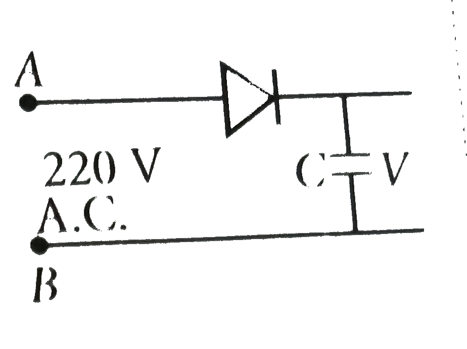
A 220 V ac supply is connected between points A and B as shown 220 V in figure. What will be the potential AC difference V across the capacitor?
 A220 VB110 VC0 VD200√2V
A capacitor or capacitance C1 is charge to a potential V and then connected in parallel to an uncharged capacitor of capacitance C2. The fianl potential difference across each capacitor will be
AC1VC1+C2BC2VC1+C2C1+C2C1D1−C2C1
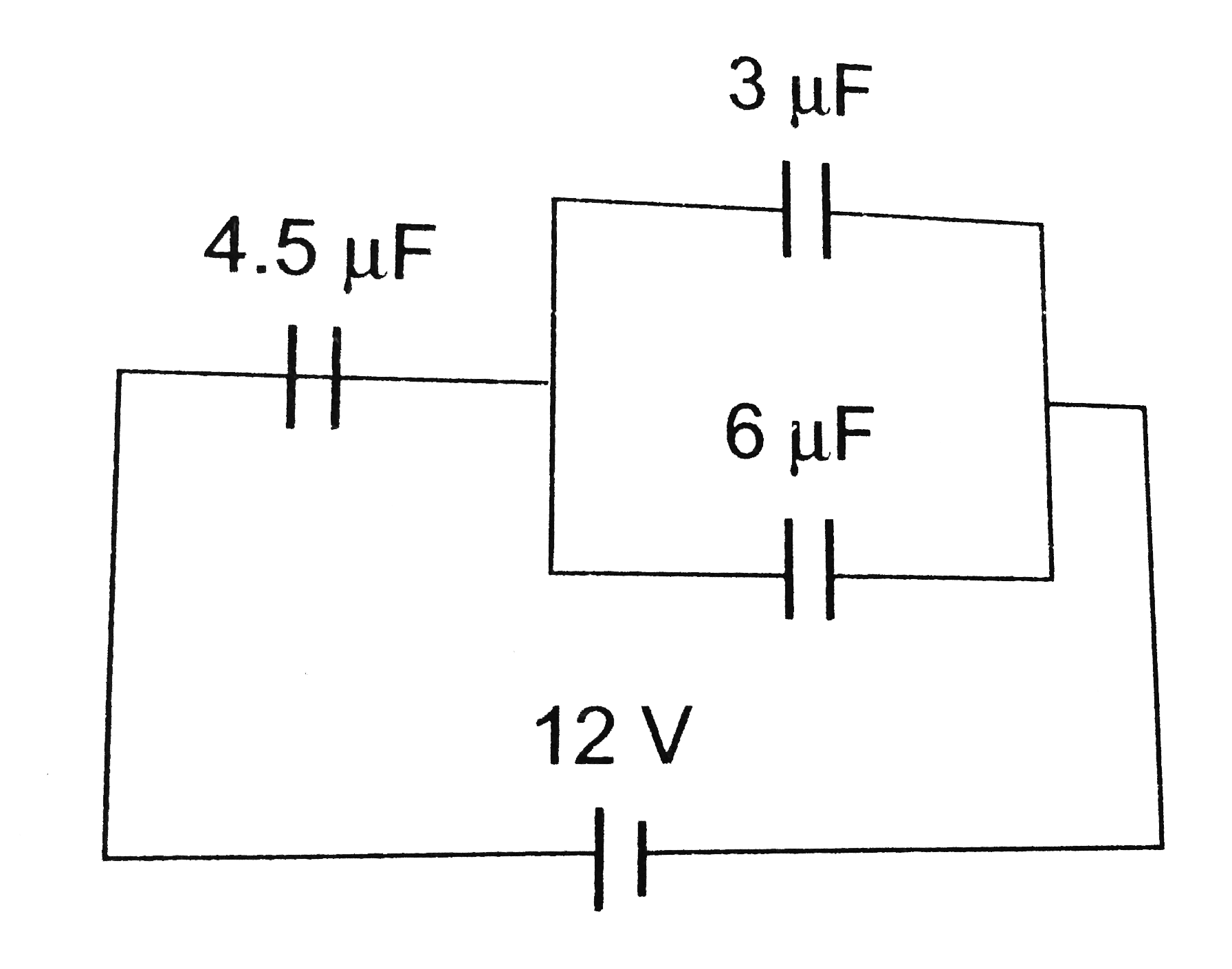
In the circuit shown in the figure, the potential difference across the 4.5μF capacitor is
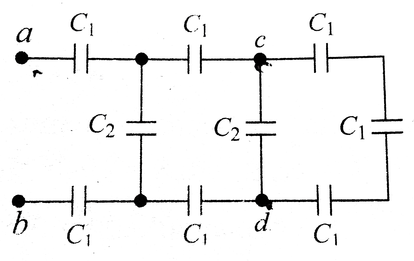
View SolutionIn each capacitance C1 is 6.0μF, and each capacitance C2 is 4.0μF.
 .
.
The equivalent capacitance of the netwok between ponts a and b is.
View SolutionA 220 V A supply is connected between points A and B in figure. What will be the potential difference V across the capacitor?
View SolutionIn the circuit shown in the figure, the potential difference across the 4.5μF capacitor is

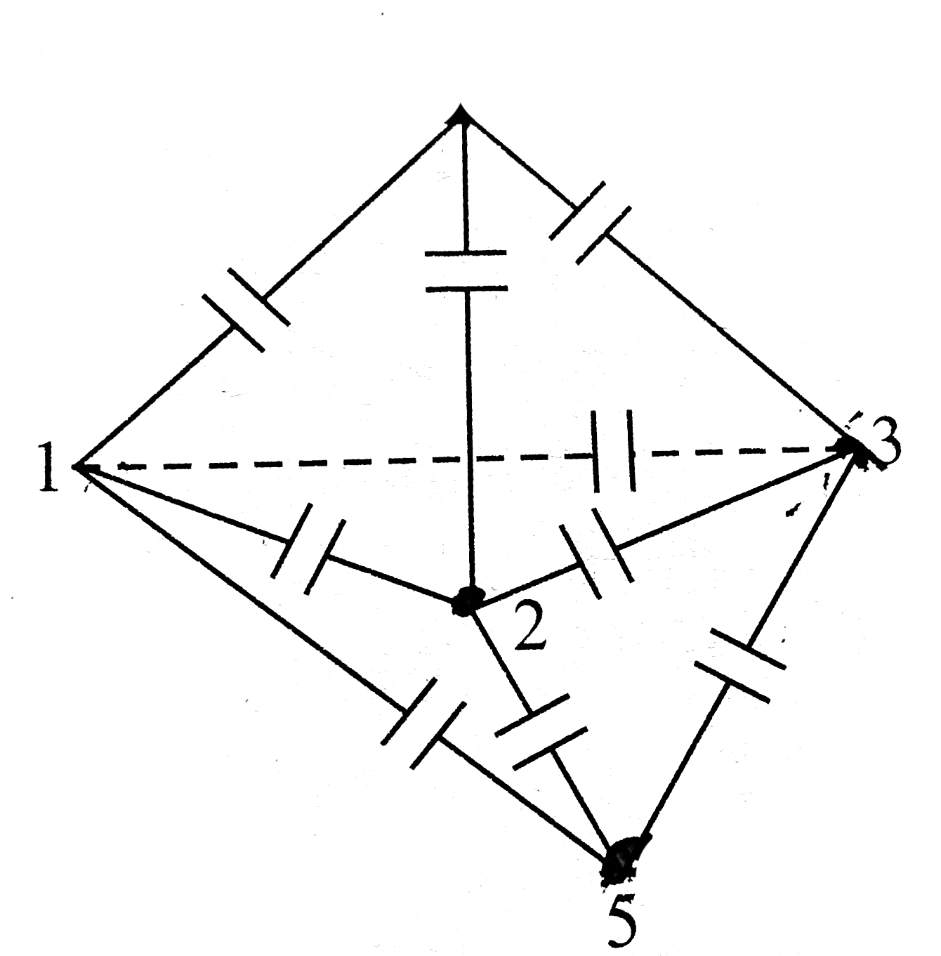
View SolutionEach capacitor has cpacitance C.
 .
.
The equivalent capacitance between 4 and 5 is .
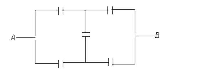
View SolutionEach capacitor shown in the figure is 2μF. Then the equivalent capacitance between points A and B is
View Solution
