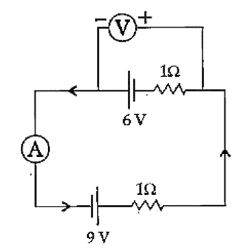
Which of the following wiring diagrams could be used to experimentally determine R using ohm's law? Assume an ideal voltmeter and an ideal ammeter.
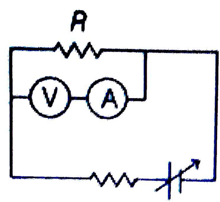
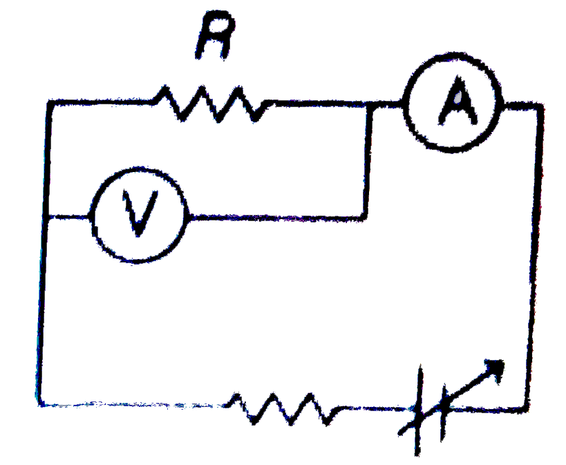
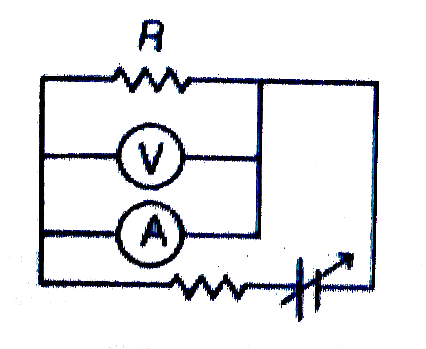
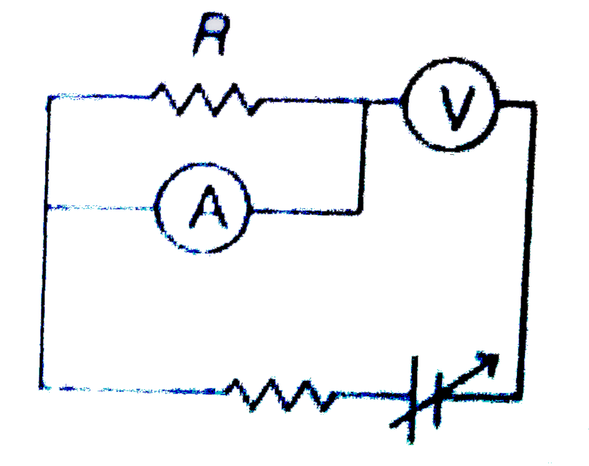
The correct Answer is:B
To determine the resistance R using Ohm's law experimentally, we need to set up a circuit that allows us to measure both the current flowing through the resistor and the voltage across it. Here’s a step-by-step solution:
Step 1: Understand Ohm's Law
Ohm's law states that V=I⋅R, where:
- V is the voltage across the resistor,
- I is the current flowing through the resistor,
- R is the resistance.
To determine R, we need to measure V and I.
Step 2: Set Up the Circuit
1. Connect the Resistor: Place the resistor R in the circuit.
2. Connect the Ammeter: Connect an ideal ammeter in series with the resistor. This allows us to measure the current I flowing through the resistor.
3. Connect the Voltmeter: Connect an ideal voltmeter in parallel with the resistor. This allows us to measure the voltage V across the resistor.
Step 3: Measure Voltage and Current
- Turn on the power supply and adjust it to a known value.
- Record the current I displayed on the ammeter.
- Record the voltage V displayed on the voltmeter.
Step 4: Calculate Resistance
Using the values obtained from the measurements:
R=VI
This formula gives us the resistance R of the resistor based on the measured voltage and current.
Step 5: Repeat Measurements
To ensure accuracy, repeat the measurements for different voltage settings and calculate R each time. The average value can provide a more reliable result.
Conclusion
The wiring diagram that connects the voltmeter in parallel and the ammeter in series with the resistor is the correct setup to experimentally determine R using Ohm's law.
---
Ohm's law states that V=I⋅R, where:
- V is the voltage across the resistor,
- I is the current flowing through the resistor,
- R is the resistance.
1. Connect the Resistor: Place the resistor R in the circuit.
2. Connect the Ammeter: Connect an ideal ammeter in series with the resistor. This allows us to measure the current I flowing through the resistor.
3. Connect the Voltmeter: Connect an ideal voltmeter in parallel with the resistor. This allows us to measure the voltage V across the resistor.
- Turn on the power supply and adjust it to a known value.
- Record the current I displayed on the ammeter.
- Record the voltage V displayed on the voltmeter.
Using the values obtained from the measurements:
R=VI
This formula gives us the resistance R of the resistor based on the measured voltage and current.
To ensure accuracy, repeat the measurements for different voltage settings and calculate R each time. The average value can provide a more reliable result.
The wiring diagram that connects the voltmeter in parallel and the ammeter in series with the resistor is the correct setup to experimentally determine R using Ohm's law.
Topper's Solved these Questions
Similar Questions
Knowledge Check
Which of the following apparatus is used to determine the Young's modulus of the material of a gives given wires?
ASearleBsonometerCMetre bridgeDResonance tube
Express which of the following set ups can be used to verify
ohm's law?
View SolutionWhich of the following diagrams (figure) depicts ideal gas behaviour?
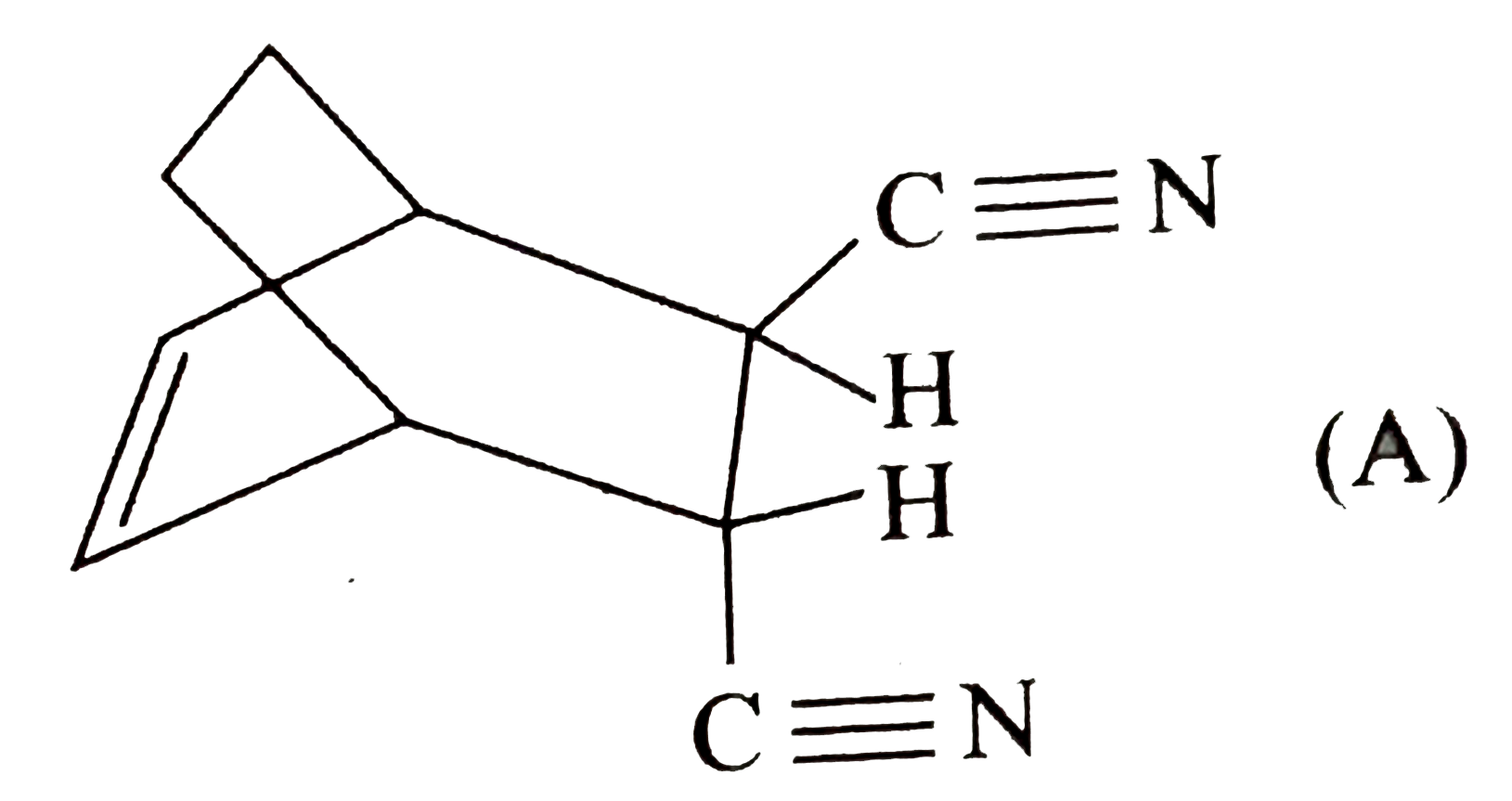
View SolutionWhich of the following dienes an dienophiles could be used to synthesise the following compound (A) ?
View SolutionWhich of the following techniques cannot be used to determine the genetic defect of an embryo?
View SolutionWhich of the following is used to determine the rate of transpiration in plants
View SolutionWhich of the following circuits gives the correct value of resistance, when computed by using R=(V/I) where V and I are voltmeter and ammeter reading, respectively? The meters are not ideal.
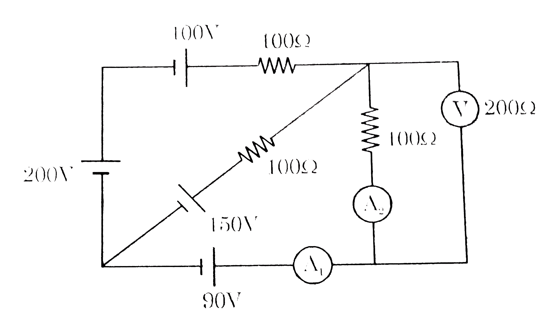
View SolutionWhich of the following options are CORRECT (ammeters are ideal).
View Solution

