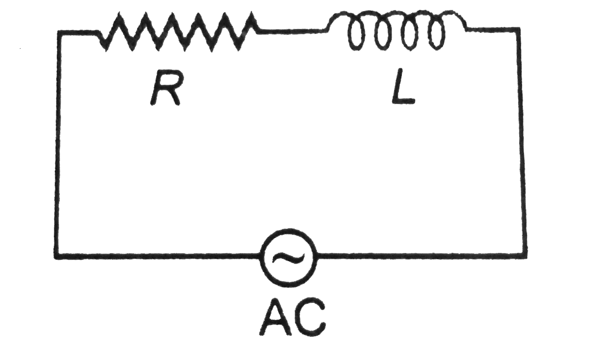
Find the voltage across the various elements, i.e., resistance, capacitance and inductance which are in series and having values 1000Ω,1μF and 2.0 H respectively . Given emf as,
V = 100sqrt2 sin 1000 t V
To solve the problem of finding the voltage across the various elements (resistor, capacitor, and inductor) in a series circuit, we will follow these steps:
Given Data:
- Resistance, R=1000Ω
- Capacitance, C=1μF=1×10⁻⁶F
- Inductance, L=2.0H
- EMF, V=100√2sin(1000t)
Step 1: Determine the RMS Voltage
The peak voltage V0 is given as 100√2. The RMS voltage Vrms can be calculated using the formula:
Vrms=V0√2
Substituting the value of V0:
Vrms=100√2√2=100V
Step 2: Calculate the Reactance of Capacitor and Inductor
The angular frequency ω can be derived from the sine function:
ω=1000rad/s
Capacitive Reactance XC:
XC=1ωC=11000×1×10−6=1000Ω
Inductive Reactance XL:
XL=ωL=1000×2=2000Ω
Step 3: Calculate the Total Impedance Z
The total impedance Z in a series circuit is given by:
Z=√R2+(XL−XC)2
Substituting the values:
Z=√10002+(2000−1000)2=√10002+10002=√2×10002=1000√2Ω
Step 4: Calculate the RMS Current Irms
Using Ohm's law for AC circuits:
Irms=VrmsZ
Substituting the values:
Irms=1001000√2=1001414.21≈0.0707A
Step 5: Calculate the Voltage across each element
Voltage across the Resistor VR:
VR=Irms×R=0.0707×1000=70.7V
Voltage across the Inductor VL:
VL=Irms×XL=0.0707×2000=141.4V
Voltage across the Capacitor VC:
VC=Irms×XC=0.0707×1000=70.7V
Final Results:
- Voltage across the Resistor, VR=70.7V
- Voltage across the Inductor, VL=141.4V
- Voltage across the Capacitor, VC=70.7V
- Resistance, R=1000Ω
- Capacitance, C=1μF=1×10⁻⁶F
- Inductance, L=2.0H
- EMF, V=100√2sin(1000t)
The peak voltage V0 is given as 100√2. The RMS voltage Vrms can be calculated using the formula:
Vrms=V0√2
Substituting the value of V0:
Vrms=100√2√2=100V
The angular frequency ω can be derived from the sine function:
ω=1000rad/s
XC=1ωC=11000×1×10−6=1000Ω
XL=ωL=1000×2=2000Ω
The total impedance Z in a series circuit is given by:
Z=√R2+(XL−XC)2
Substituting the values:
Z=√10002+(2000−1000)2=√10002+10002=√2×10002=1000√2Ω
Using Ohm's law for AC circuits:
Irms=VrmsZ
Substituting the values:
Irms=1001000√2=1001414.21≈0.0707A
Voltage across the Resistor VR:
VR=Irms×R=0.0707×1000=70.7V
VL=Irms×XL=0.0707×2000=141.4V
VC=Irms×XC=0.0707×1000=70.7V
- Voltage across the Resistor, VR=70.7V
- Voltage across the Inductor, VL=141.4V
- Voltage across the Capacitor, VC=70.7V
Similar Questions
Find the voltage across the various elements, i.e., resistance, capacitance and inductance which are in series and having values 1000Ω,1μF and 2.0H, respectively. Given emf is
V=100√2sin1000t voltView SolutionFind the potential difference across resistance, capacitance and inductance in series LCR circuit where L=2.0H,C=1μFandR=100Ω. The applied emf has the form V=100√2sin(1000t)
View SolutionIn a series LCR the voltage across resistance, capacitance and inductance is 10V each. If the capacitance is shor t circulated, the voltage across the inducatance will be
View SolutionA circuit contains resistance R and an inductance L in series. An alternating voltage V=V0sinωt is applied across it. The currents in R and L respectively will be
 .View Solution
A circuit contains resistance R and an inductance L in series. An alternating voltage V=V0sinωt is applied across it. The currents in R and L respectively will be
 .View Solution
In a series LCR circuit the rms voltage across the inductance , capacitance and resistance are respectively 4 V, 8 V and 5 V . The RMS voltage of the AC source in the circuit is
View SolutionIn a series resonant circuit, the ac, voltage across resistance R, inductance L and capacitance are 5V, 10V and 10V, respectively. The ac. voltage applied to the circuit will be
View SolutionA capacitor of capacitance 100μF and a coil of resistance 50Ω and inductance 0.5H are connected in series with a110V,50HzAC source. Find the rms value of the current.
View SolutionIn the circuit shown E,F,G and H are cells of emf 2V,1V,3V and 1V respectively and their internal resistance are 2Ω,1Ω,3Ω and 1Ω respectively.
 View Solution
In the circuit shown E,F,G and H are cells of emf 2V,1V,3V and 1V respectively and their internal resistance are 2Ω,1Ω,3Ω and 1Ω respectively.
 View Solution

