Phasor Diagram
Step by step video solution for Phasor Diagram by Physics experts to help you in doubts & scoring excellent marks in Class 12 exams.
Updated on:21/07/2023Similar Questions
An ac source of voltage V=V0sinωt is connected to a series combination of L, C and R. Use the phasor diagram to obtain expressions for impedance of the circuit and phase with the voltage. What is circuit in this condition called?
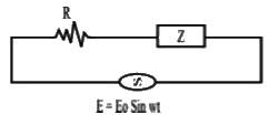
View SolutionAnalternating voltage E=E0sinωt is applied to a circuit containıng a resistor R connected in series with a black box. The current in the circuit is found to be =I0sin(ωt+π/4).

Draw the corresponding phasor diagram and find the impedance in tems of R.
View Solution
Knowledge Check
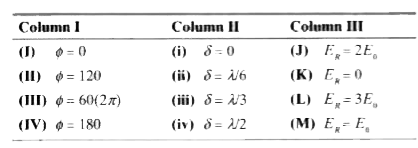
The amplitudes of two coherent waves are vector quanti- ties. In the given table, Column I shows the phase differ ence between two coherent waves, Column II shows the path difference between them and Column III shows their resultant amplitudes.

When is the phasor diagram at primary maxima?A(I) (iii) (M)B(III) (ii) (K)C(I) (i) (L)D(I) (iii) (J)The amplitudes of two coherent waves are vector quanti- ties. In the given table, Column I shows the phase differ ence between two coherent waves, Column II shows the path difference between them and Column III shows their resultant amplitudes.

When is the phasor diagram at secondary maxima?A(III) (i) (L)B(IV) (i) (J)C(III) (iv) (J)D(IV) (iv) (M)
An a.c. source, of voltage V=Vmsinωt , is applied across a series LCR circuit. Draw the phasor diagram for the circuit when the
(i) capacitive reactance exceeds the inductive reactance,
(ii) inductive reactance exceeds the capacitive reactance.
View SolutionA source of a.c. voltage V=Vmsinωt is connected to a series combination of a capacitor C and a resistor R. Draw the phasor diagram and use it to obtain the expression for (i) impedance of the circuit, and (ii) phase angle.
View SolutionA sinusoidally alternating emf is applied to an LCR series circuit . (i) Define the impedance of the circuit . (ii) Obtain the expressions for the impedance and the phase difference between the emf and current from the phasor diagram. (iii) Discuss the behaviour of the circuit for different relative values of the two reactances in the circuit.
View Solutiona) Derive the expression for the current flowing in an ideal capacitor and its reactance when connected to an ac source of voltage V=V0sinωt
b) Draw its phasor diagram.
c) If resistance is added in series to capacitor what changes will occur in the current flowing in the circuit and phase angle between voltage and current.
View Solution(a) An AC source of voltage V=V0sinωt is connected across a series combination of an inductor a capacitor and a resistor . Use the phasor diagram to obtain the expression for the impedance of the circuit and phase angle between the voltage and the current.
(b) A capacitor of unknown capacitance a resistor of 100 Ω and an inductor of self - inductance L =(4/π2) henry are in series connected to an AC source of 200 V and 50 Hz . Calculate the value of the capacitance and the current that flows in the circuit when the current is in phase with the voltage .
View SolutionA device X is connected across an a.c. source of voltage V=Vmsinωt. The current through X is given asI=I∘sin(ωt+π2)
(a) Identify the device X and write the expression for its reactance.
(b) Draw graphs showing variation of voltage and current with time over one cycle of a.c. for X.
(C) How does the reactance of the device X vary with frequency of the a.c. ? Show this variation graphically.
(d) Draw the phasor diagram for the device X.
View Solution
