The figure below shown a battery with emf 15 V in a circuit with R1=30(Ω),R3=20(ΩandL=3.0H. The switch S is initially in the open position and is then closed at time t = 0. Then the graph which shows the correct variation of current through battery after switch S is closed

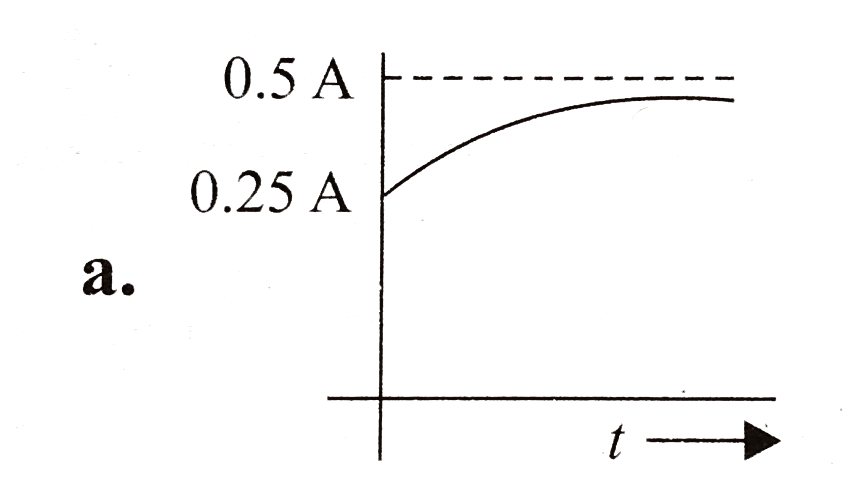
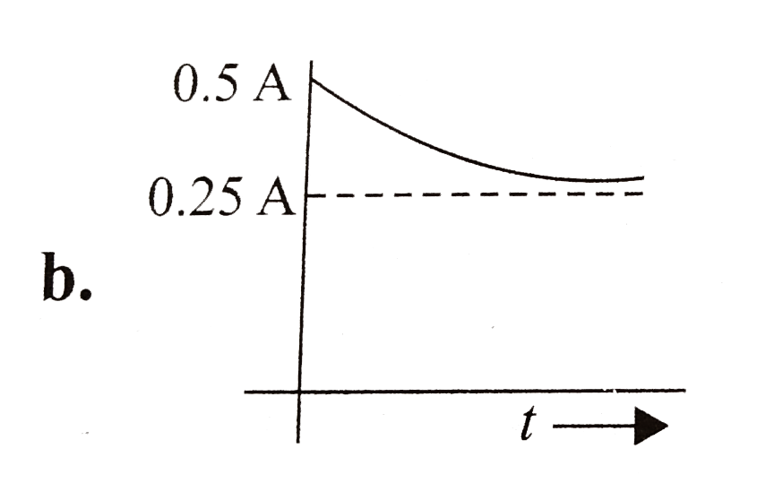
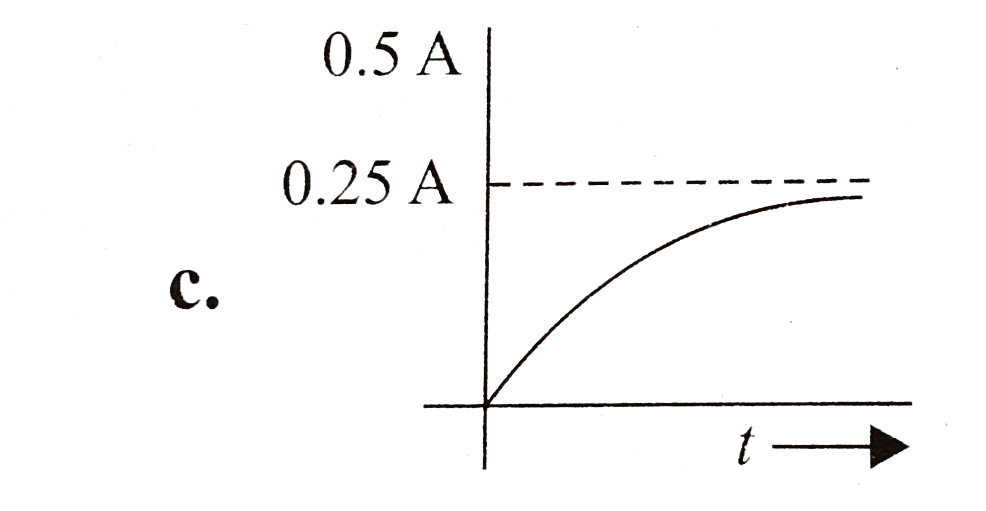

The correct Answer is:A
Initially no current in the inductor, so initial current
(i1)=15R1+R2+R3=0.25A
In steady state, no current in R2andR3. So final current through battery: I2=15R1=0.5A.
Topper's Solved these Questions
- BOOK - CENGAGE PHYSICS ENGLISHCHAPTER - MISCELLANEOUS VOLUME 5EXERCISE - Multiple Correct34videos
MISCELLANEOUS VOLUME 5
- BOOK - CENGAGE PHYSICS ENGLISHCHAPTER - MISCELLANEOUS VOLUME 5EXERCISE - Linked Comprehension84videos
MISCELLANEOUS VOLUME 5
- BOOK - CENGAGE PHYSICS ENGLISHCHAPTER - MISCELLANEOUS VOLUME 3EXERCISE - True and False3videos
MISCELLANEOUS VOLUME 3
- BOOK - CENGAGE PHYSICS ENGLISHCHAPTER - NUCLEAR PHYSICSEXERCISE - ddp.5.514videos
NUCLEAR PHYSICS
Similar Questions
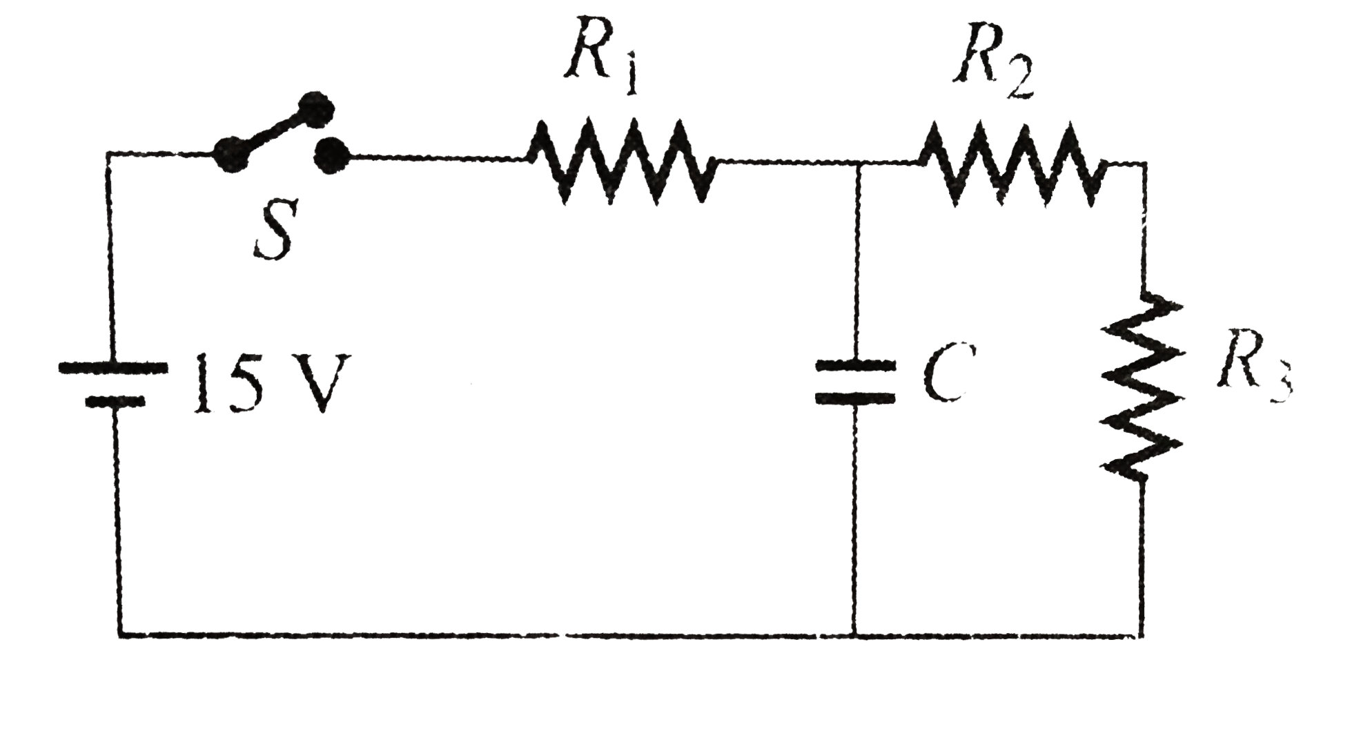
Figure shows a battery with emf 15 V in a circuit with R1=30Ω,R2=10Ω,R3=20Ω and capacitance C=10μF. The switch S is initially in the open position and is then closed at time t= 0. What will be the fimal steady - state charge on capacitor?
 View Solution
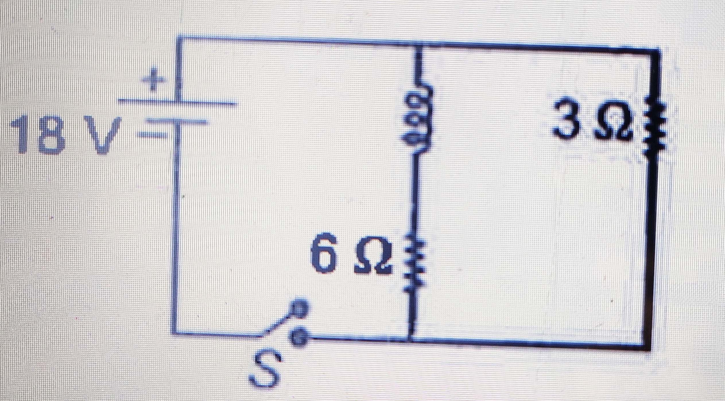
In the following circuit the value of current i through the battery just after switch S is closed is
 View Solution
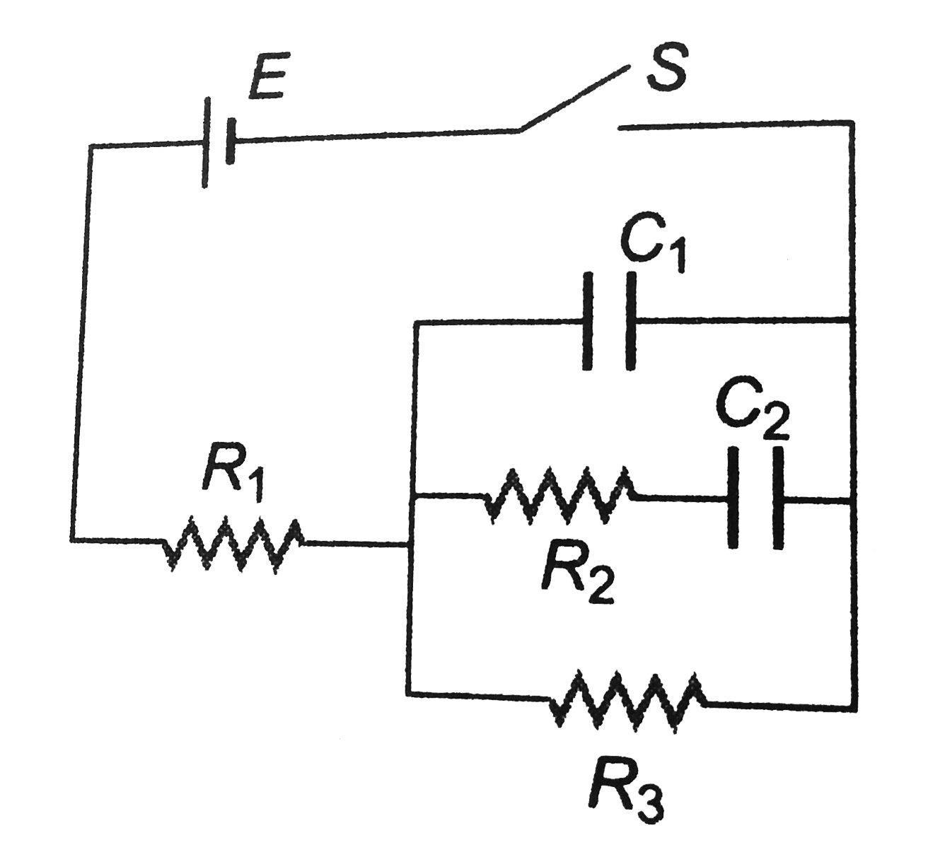
In the circuit diagram the current through the battery immediately after the switch S is closed is
 View Solution
Consider the circuit shown in figure. The current through the battery a long time after the switch S is closed is:
 View Solution
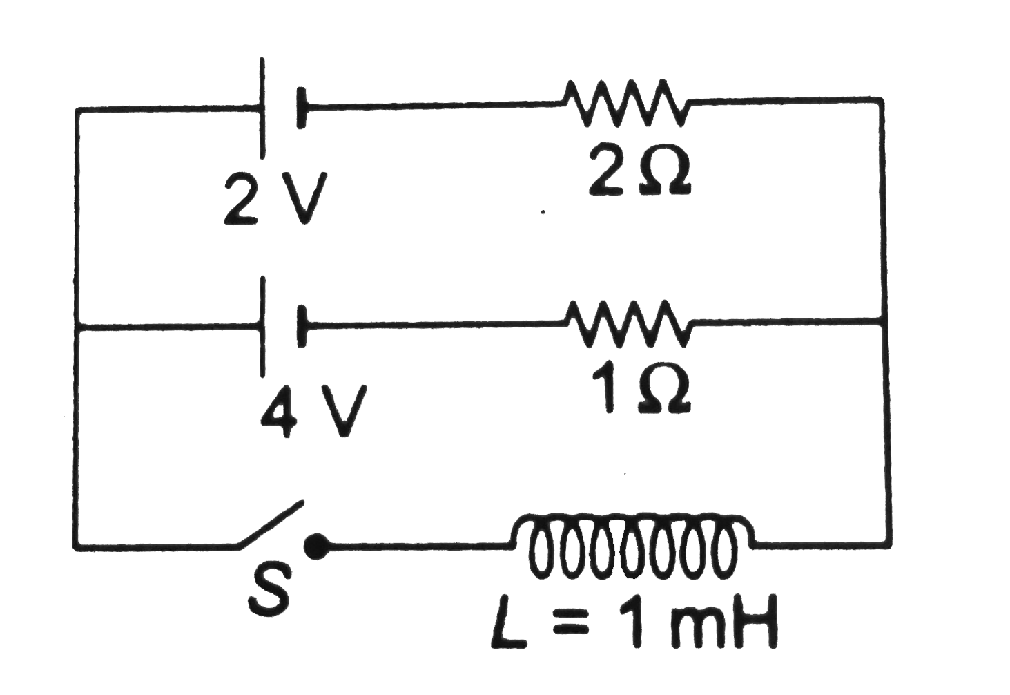
In the circuit shown, switch S is closed at time t=0. Find the current through the inductor as a function of time t.
 View Solution
Switch is closed at t=0 then the current in the circuit at t=L2R is
_PHY_E06_157_Q01.png) View Solution
View SolutionIn the given circuit, the switch S is closed at time t=0 then select the correct statement for current l in resistance PQ as shown in the figure
_PHY_E05_091_Q01.png) View Solution
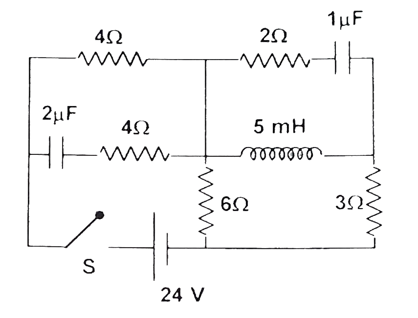
View SolutionIn the circuit shown, the switch 'S' is closed at t=0. Then the current through the battery steady state reached is
 View Solution
Consider the situation shown in figure. The switch S is open for a long time and then closed.

Find the charge flown through the battery when the switch S is closed.View SolutionIn the circuit shown in figure switch S is closed at time t=0. The charge which passes through the battery in one time constant is
 View Solution

