Consider the circuit shown. The switch is closed at t = 0. Currents in various branches are marked. Which of the following is correct?
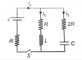
At t=0,l=ε3R,l2=ε6R,l3=ε6R
At t=0,l=ε3R,l3=ε3R
At t=∞,l1=ε2R,l2=ε4R,l3=ε4R
At t=∞,l,=ε2R,l2=ε2R
The correct Answer is:B, D
Step by step video & image solution for Consider the circuit shown. The switch is closed at t = 0. Currents in various branches are marked. Which of the following is correct? by Physics experts to help you in doubts & scoring excellent marks in Class 12 exams.
Updated on:21/07/2023Topper's Solved these Questions
- ELECTROMAGNETIC INDUCTIONBOOK - AAKASH INSTITUTE ENGLISHCHAPTER - ELECTROMAGNETIC INDUCTIONEXERCISE - Assignment (SECTION - D)
6 Videos
- ELECTROMAGNETIC INDUCTIONBOOK - AAKASH INSTITUTE ENGLISHCHAPTER - ELECTROMAGNETIC INDUCTIONEXERCISE - Assignment (SECTION - E)
8 Videos
- ELECTROMAGNETIC INDUCTIONBOOK - AAKASH INSTITUTE ENGLISHCHAPTER - ELECTROMAGNETIC INDUCTIONEXERCISE - Assignment (SECTION - B)
22 Videos
- ELECTRIC CHARGES AND FIELDS BOOK - AAKASH INSTITUTE ENGLISHCHAPTER - ELECTRIC CHARGES AND FIELDS EXERCISE - comprehension
3 Videos
- ELECTROMAGNETIC WAVESBOOK - AAKASH INSTITUTE ENGLISHCHAPTER - ELECTROMAGNETIC WAVESEXERCISE - ASSIGNMENT SECTION - D Assertion-Reason Type Questions
25 Videos
Similar Questions
In the circuit shown, the switch is closed at t=0, the currents I1,I2 and I3 are
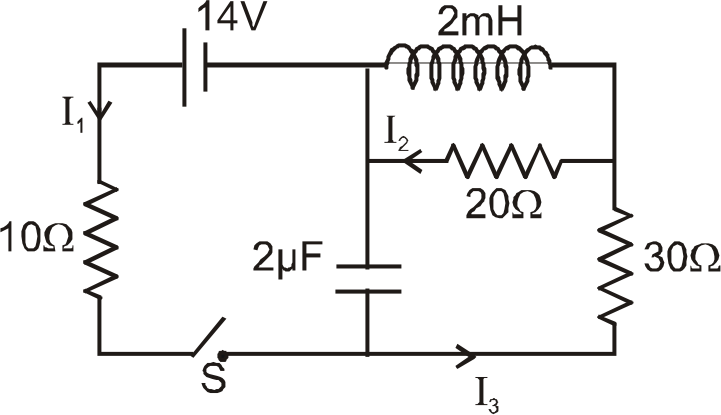
View SolutionIn the circuit shown, the switch is closed at t=0. Select the correct alternative(s)
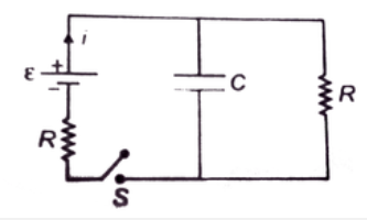
View Solution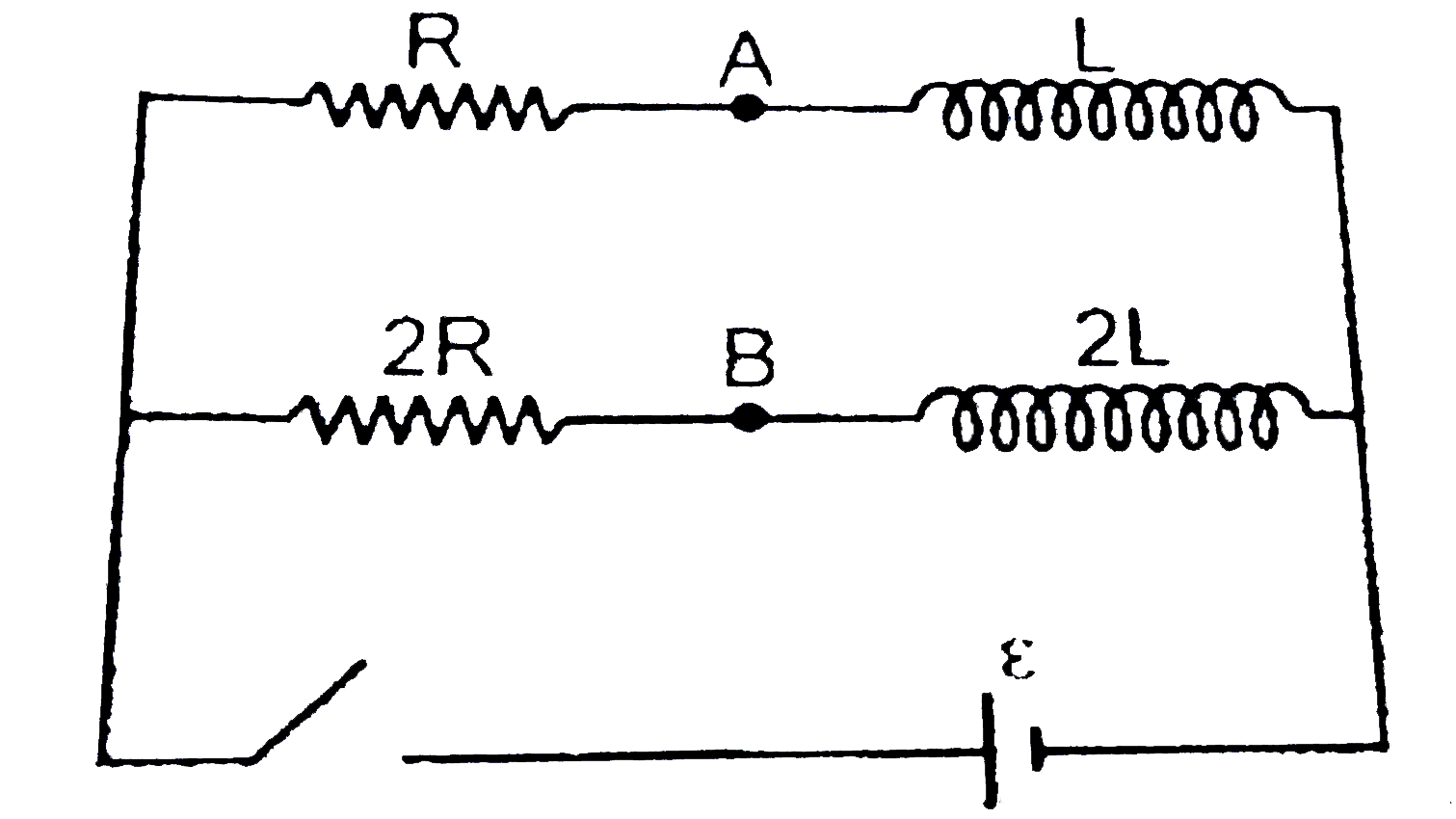
In given LR circuit the switch S is closed at time t=0 then
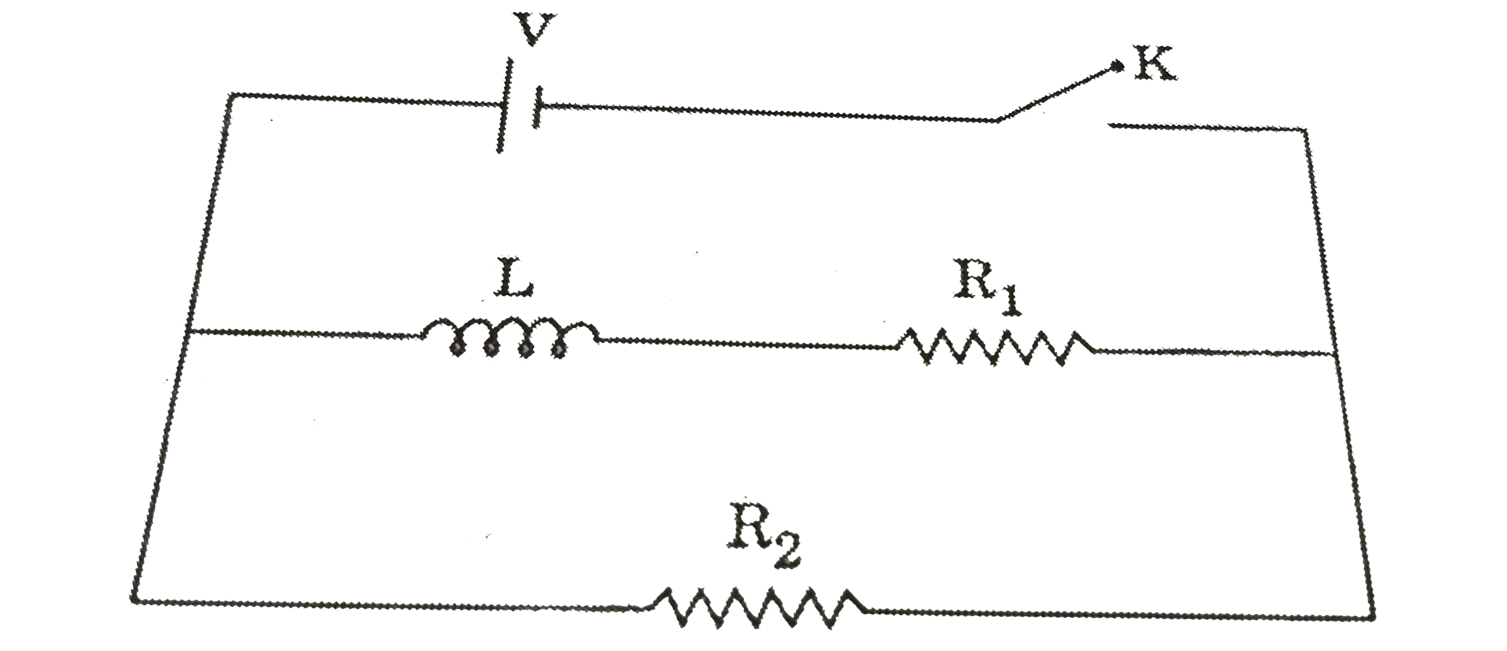
View SolutionIn the circuit shown below, the key K is closed at t = 0. The current through the battery is
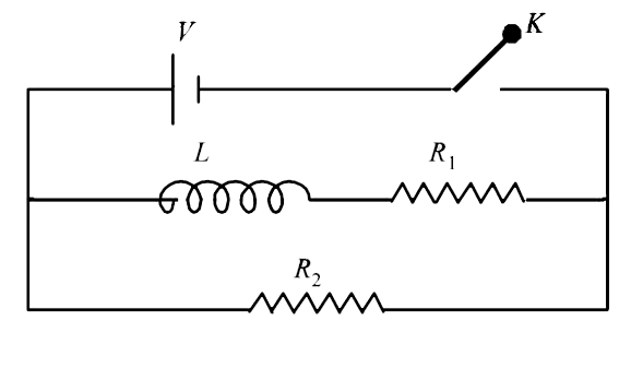
View SolutionIn the circuit shown below, the key K is closed at t =0. The current through the battery is
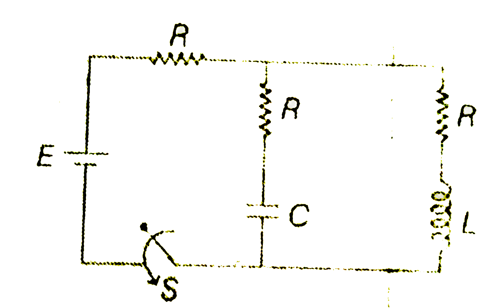
View SolutionIn the circuit as shown in the figure, switch S is added at t=0. Then:
View Solution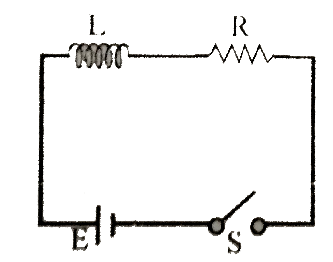
In the LR circuit as shown in figure, te switch is closed at t=0, mark the incorrect statement of the following
View SolutionIn the circuit shown in figure switch S is closed at time t=0
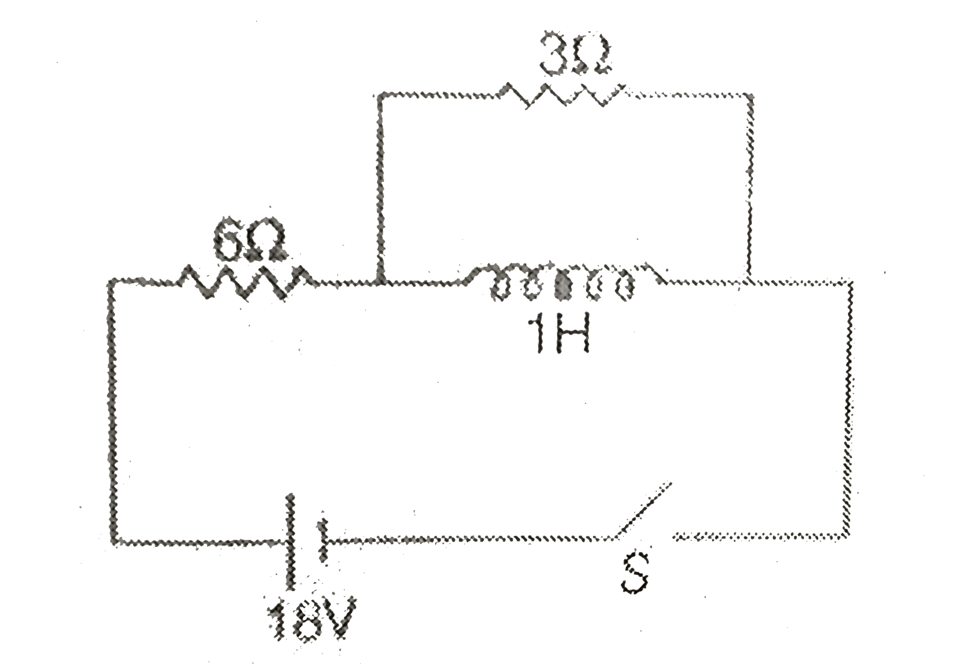
Current I from the battery at time t is given by
View SolutionIn the circuit shown, the switch 'S' is closed at t=0. Then the current through the battery steady state reached is
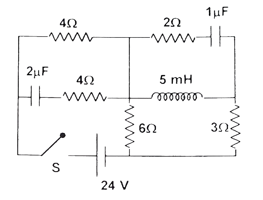
View SolutionIn the circuit shown in figure the switch S is closed at t = 0. A long time after closing the switch
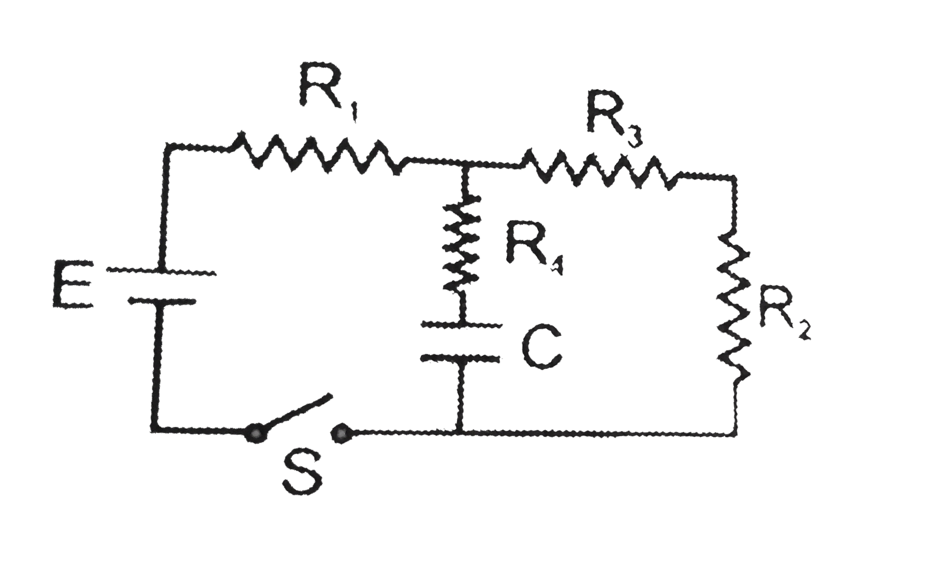
View Solution
