For inputs (A, B) and output(Y) of the following gate can be expressed as
A⊕B
A.B
A+B
¯¯¯A+¯¯¯B
The correct Answer is:A
To solve the problem, we need to analyze the logic gates involved and express the output Y in terms of inputs A and B. Let's break it down step by step.
Step 1: Identify the Gates
We have five gates in the circuit, and we will analyze each gate one by one. We will denote them as Gate 1, Gate 2, Gate 3, Gate 4, and Gate 5.
Step 2: Analyze Gate 1
For Gate 1, the input is B and B′ (where B′ is the NOT operation on B). The output for this gate can be expressed as:
Y1=B′
This means the output of Gate 1 is the complement of B.
Hint: Remember that the output of a NOT gate is the inverse of the input.
Step 3: Analyze Gate 2
For Gate 2, the input is A′ (where A′ is the NOT operation on A). The output for this gate can be expressed as:
Y2=A′
This means the output of Gate 2 is the complement of A.
Hint: A NOT gate only has one input and outputs the opposite value.
Step 4: Analyze Gate 3
For Gate 3, the input is A⋅B′ (AND operation between A and B′). The output for this gate can be expressed as:
Y3=A⋅B′
This means the output of Gate 3 is true when A is true and B is false.
Hint: The AND gate outputs true only when both inputs are true.
Step 5: Analyze Gate 4
For Gate 4, the input is A′⋅B (AND operation between A′ and B). The output for this gate can be expressed as:
Y4=A′⋅B
This means the output of Gate 4 is true when A is false and B is true.
Hint: Again, remember that the AND gate requires both inputs to be true for the output to be true.
Step 6: Combine Outputs from Gate 3 and Gate 4
Now, we need to combine the outputs from Gate 3 and Gate 4 to get the final output Y. The output Y can be expressed as:
Y=Y3+Y4=(A⋅B′)+(A′⋅B)
This is the expression for the output in terms of inputs A and B.
Hint: The '+' symbol represents the OR operation, which outputs true if at least one of the inputs is true.
Step 7: Final Output Expression
The final output expression can be simplified to:
Y=A⋅B′+A′⋅B
This expression represents the XOR operation, which is true when either A or B is true, but not both.
Hint: Recognize that this expression corresponds to the XOR logic gate.
Conclusion
The output Y for the given inputs A and B can be expressed as:
Y=A⊕B
where ⊕ denotes the XOR operation.
We have five gates in the circuit, and we will analyze each gate one by one. We will denote them as Gate 1, Gate 2, Gate 3, Gate 4, and Gate 5.
For Gate 1, the input is B and B′ (where B′ is the NOT operation on B). The output for this gate can be expressed as:
Y1=B′
This means the output of Gate 1 is the complement of B.
For Gate 2, the input is A′ (where A′ is the NOT operation on A). The output for this gate can be expressed as:
Y2=A′
This means the output of Gate 2 is the complement of A.
For Gate 3, the input is A⋅B′ (AND operation between A and B′). The output for this gate can be expressed as:
Y3=A⋅B′
This means the output of Gate 3 is true when A is true and B is false.
For Gate 4, the input is A′⋅B (AND operation between A′ and B). The output for this gate can be expressed as:
Y4=A′⋅B
This means the output of Gate 4 is true when A is false and B is true.
Now, we need to combine the outputs from Gate 3 and Gate 4 to get the final output Y. The output Y can be expressed as:
Y=Y3+Y4=(A⋅B′)+(A′⋅B)
This is the expression for the output in terms of inputs A and B.
The final output expression can be simplified to:
Y=A⋅B′+A′⋅B
This expression represents the XOR operation, which is true when either A or B is true, but not both.
The output Y for the given inputs A and B can be expressed as:
Y=A⊕B
where ⊕ denotes the XOR operation.
Topper's Solved these Questions
- SEMICONDUCTOR ELECTRONICS (MATERIAL, DEVICES AND SIMPLE CIRUITS )BOOK - AAKASH INSTITUTE ENGLISHCHAPTER - SEMICONDUCTOR ELECTRONICS (MATERIAL, DEVICES AND SIMPLE CIRUITS )EXERCISE - Assignment section -C (Previous years type question)
110 Videos
- SEMICONDUCTOR ELECTRONICS (MATERIAL, DEVICES AND SIMPLE CIRUITS )BOOK - AAKASH INSTITUTE ENGLISHCHAPTER - SEMICONDUCTOR ELECTRONICS (MATERIAL, DEVICES AND SIMPLE CIRUITS )EXERCISE - Assignment SECTION - D (Assertion & reason type Question)
10 Videos
- SEMICONDUCTOR ELECTRONICS (MATERIAL, DEVICES AND SIMPLE CIRUITS )BOOK - AAKASH INSTITUTE ENGLISHCHAPTER - SEMICONDUCTOR ELECTRONICS (MATERIAL, DEVICES AND SIMPLE CIRUITS )EXERCISE - Assignment section -A (Objective Type Question)
43 Videos
- RAY OPTICS AND OPTICAL INSTRUMENTSBOOK - AAKASH INSTITUTE ENGLISHCHAPTER - RAY OPTICS AND OPTICAL INSTRUMENTSEXERCISE - ASSIGNMENT (SECTION - D)
16 Videos
- SEMICONDUCTOR ELECTRONICS: MATERIALS, DEVICES AND SIMPLE CIRCUITSBOOK - AAKASH INSTITUTE ENGLISHCHAPTER - SEMICONDUCTOR ELECTRONICS: MATERIALS, DEVICES AND SIMPLE CIRCUITSEXERCISE - Assignment (Section-D (Assertion and reason))
5 Videos
Similar Questions
Knowledge Check
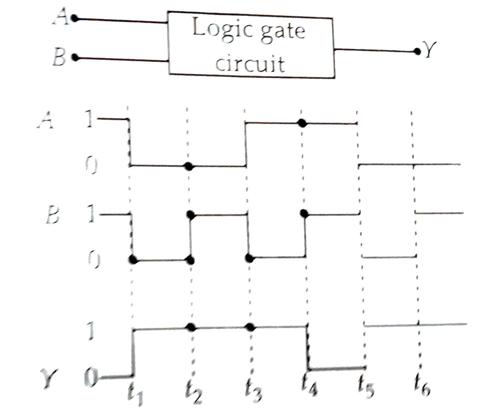
The following figure shows a logic gate circuit with two inputs A and B and the output Y. The voltage waveforms of A,B and Y are as given :

The logic gate isANOR gateBOR gateCAND gateDNAND gate

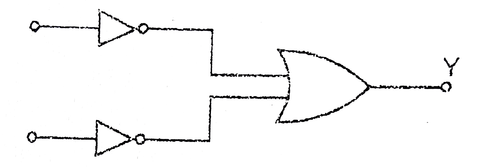
The output Y for the following logic gate circuit will be-
View SolutionWhich of the following is the boolean expression for XOR gate?
View SolutionThe following figure shows a logic gate circuit with two inputs A and B output C. The voltage waveforms of A,B and C are as shown in second figure given below :-
_E01_436_Q01.png)
The logic circuit gate is :-
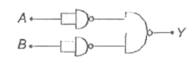
View SolutionOutput Y of the gate shown in figure

View SolutionThe output of OR gate is 1
View SolutionThe output of OR gate is 1
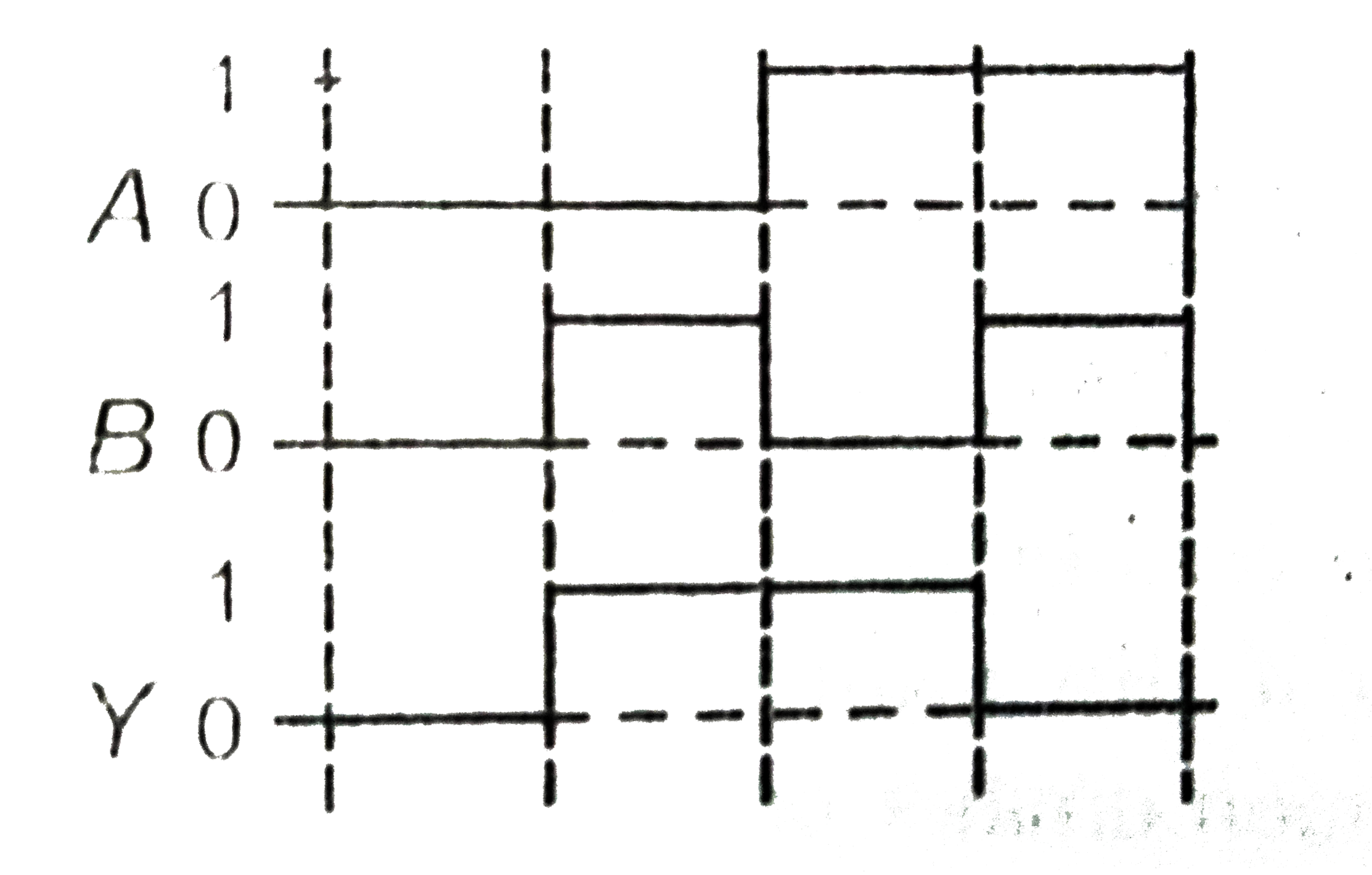
View SolutionThere is a gate with two inputs A and B, and one output Y. using the input and output wave forms identify the gate

View Solution


