Calculate the current l in the following circuit, if all the diodes are ideal. All resistances are 200Ω
Zero
1A
2A
4A
The correct Answer is:B
To calculate the current I in the given circuit with ideal diodes and resistances of 200Ω, we can follow these steps:
1. Identify the Circuit Configuration:
- The circuit consists of multiple branches with diodes and resistors. The resistors are all 200Ω, and we have a voltage supply of 200V.
2. Determine the State of the Diodes:
- Since the diodes in branches GH and CD are reverse-biased, they do not conduct current. Therefore, we can ignore these branches for the current calculation.
- The only branch that conducts current is branch EF, where the diode is forward-biased.
3. Apply Ohm's Law:
- Ohm's Law states that V=I×R, where V is voltage, I is current, and R is resistance.
- We will use this law to find the current through the conducting branch (EF).
4. Calculate the Current:
- The voltage across the conducting branch EF is 200V.
- The resistance in this branch is 200Ω.
- Using Ohm's Law, we can rearrange it to find the current:
I=VR=200V200Ω=1A
5. Conclusion:
- The current I in the circuit is 1A.
Final Answer:
The current I in the circuit is 1A.
- The circuit consists of multiple branches with diodes and resistors. The resistors are all 200Ω, and we have a voltage supply of 200V.
- Since the diodes in branches GH and CD are reverse-biased, they do not conduct current. Therefore, we can ignore these branches for the current calculation.
- The only branch that conducts current is branch EF, where the diode is forward-biased.
- Ohm's Law states that V=I×R, where V is voltage, I is current, and R is resistance.
- We will use this law to find the current through the conducting branch (EF).
- The voltage across the conducting branch EF is 200V.
- The resistance in this branch is 200Ω.
- Using Ohm's Law, we can rearrange it to find the current:
I=VR=200V200Ω=1A
- The current I in the circuit is 1A.
The current I in the circuit is 1A.
Topper's Solved these Questions
- SEMICONDUCTOR ELECTRONICS (MATERIAL, DEVICES AND SIMPLE CIRUITS )BOOK - AAKASH INSTITUTE ENGLISHCHAPTER - SEMICONDUCTOR ELECTRONICS (MATERIAL, DEVICES AND SIMPLE CIRUITS )EXERCISE - Assignment section -C (Previous years type question)
110 Videos
- SEMICONDUCTOR ELECTRONICS (MATERIAL, DEVICES AND SIMPLE CIRUITS )BOOK - AAKASH INSTITUTE ENGLISHCHAPTER - SEMICONDUCTOR ELECTRONICS (MATERIAL, DEVICES AND SIMPLE CIRUITS )EXERCISE - Assignment SECTION - D (Assertion & reason type Question)
10 Videos
- SEMICONDUCTOR ELECTRONICS (MATERIAL, DEVICES AND SIMPLE CIRUITS )BOOK - AAKASH INSTITUTE ENGLISHCHAPTER - SEMICONDUCTOR ELECTRONICS (MATERIAL, DEVICES AND SIMPLE CIRUITS )EXERCISE - Assignment section -A (Objective Type Question)
43 Videos
- RAY OPTICS AND OPTICAL INSTRUMENTSBOOK - AAKASH INSTITUTE ENGLISHCHAPTER - RAY OPTICS AND OPTICAL INSTRUMENTSEXERCISE - ASSIGNMENT (SECTION - D)
16 Videos
- SEMICONDUCTOR ELECTRONICS: MATERIALS, DEVICES AND SIMPLE CIRCUITSBOOK - AAKASH INSTITUTE ENGLISHCHAPTER - SEMICONDUCTOR ELECTRONICS: MATERIALS, DEVICES AND SIMPLE CIRCUITSEXERCISE - Assignment (Section-D (Assertion and reason))
5 Videos
Similar Questions
Calculate the current flows through resistance 2Ω.
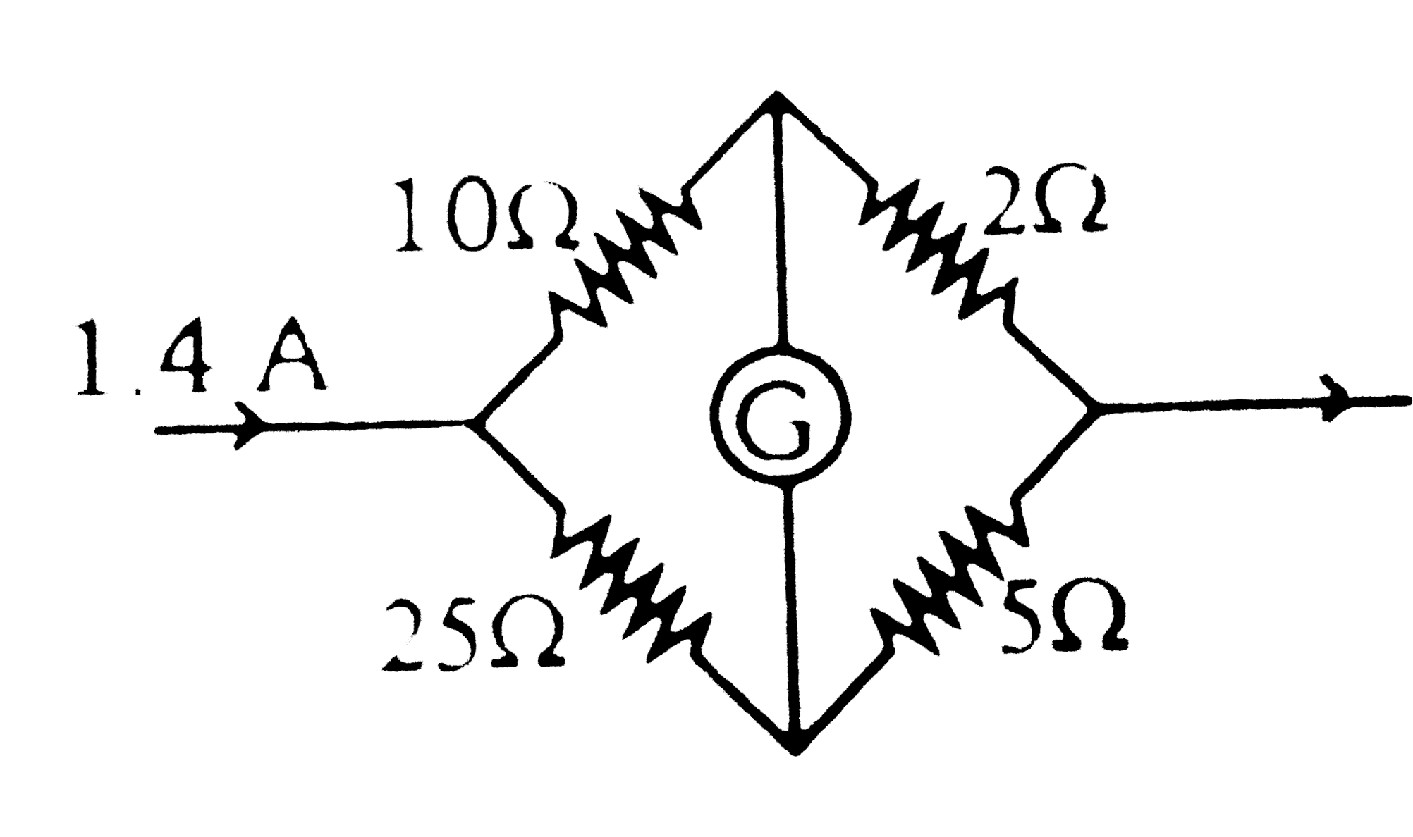
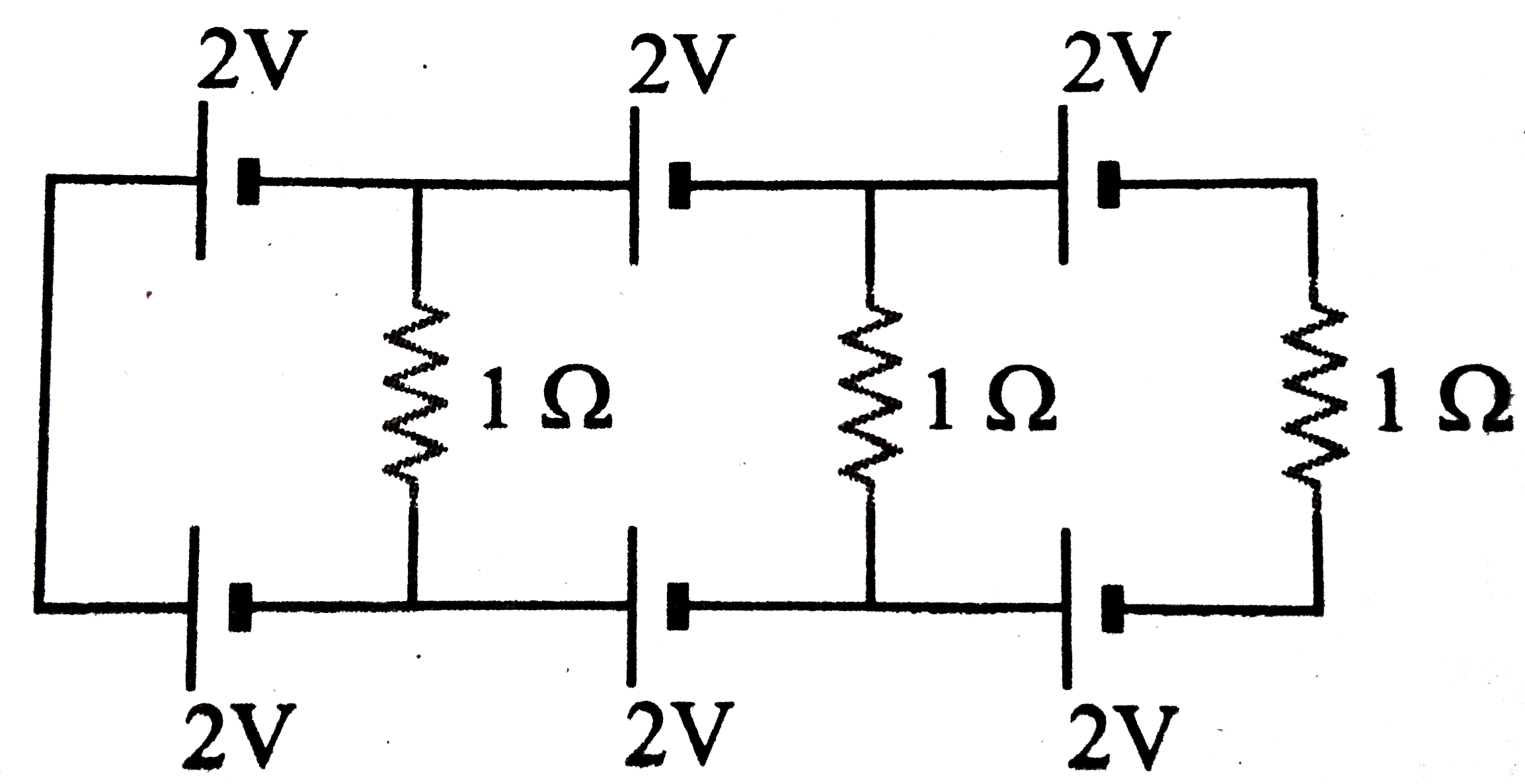
View SolutionIn the following circuit the current in each resistance is
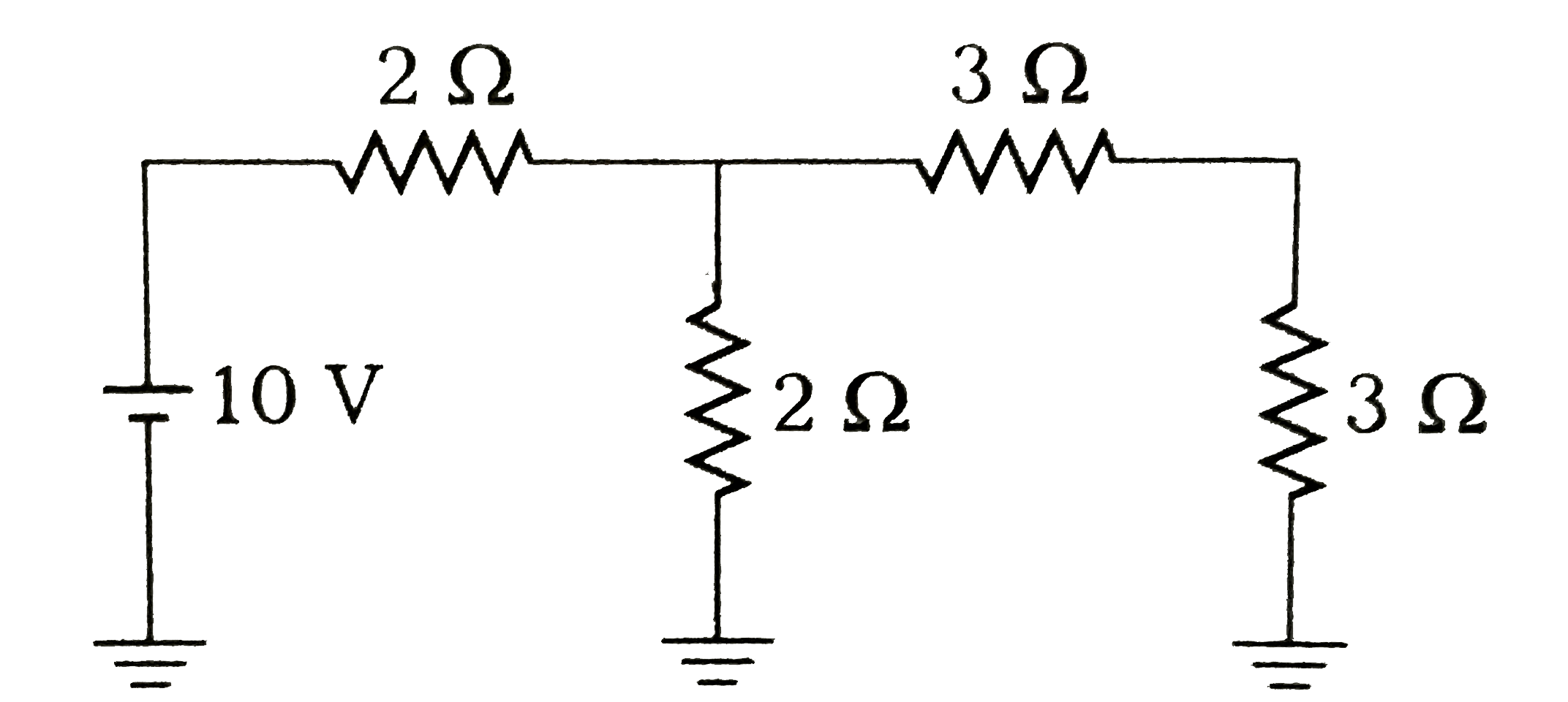
View SolutionIn the circuit shown, the current in 3Ω resistance is
View SolutionIn the following circuit the current flowing through zener diode is
View SolutionDetermine the current supplied by the battery in the circuit as shown

(ii) Find currents in resistance 2Ω and 4Ω.
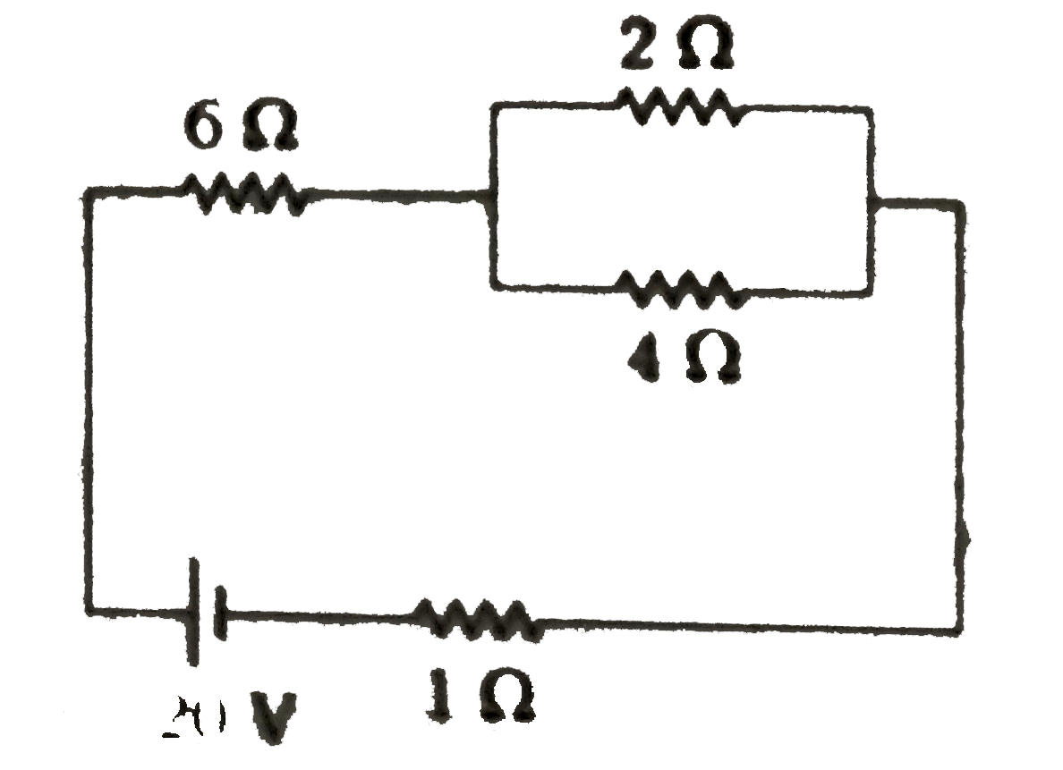
View SolutionIn the circuit shown in figure , all the cells are ideal . The currnet through 2Ω resistor is
View SolutionIn the circuit of the figure, treat diode as ideal, current in the 4Ω resistor is
View SolutionA P−N junction diode can withstand currents up to 10mA. Under forward bias, The diode has a potential drop of 0.5V across it which is assumed to be independent of current. The maximum voltage of the battery used to forward bias the diode when a resistance of 200Ω is connected in series with it is
View SolutionAn AC voltage source is applied across an R-C circuit. Angular frequency of the source is ω, resistance is R and capacitance is C. The current registered is I. If now the frequency of source is changed to ω2 (but maintaining the same voltage), the current in the circuit is found to be two third. calculate the ratio of reactance to resistance at the original frequency ω .
View SolutionIn the circuit in figure, the current flowing 5Ω resistance is :
View Solution
