n resistances each of resistance R are joined with capacitors of capacity C (each) and a battery of emf E as shown in the figure. In steady state condition ratio of charge stored in the first and last capacitor is :

n:1
(n−1):(n+1)
(n2+1):(n2−1)
1:1
The correct Answer is:D
Step by step video & image solution for n resistances each of resistance R are joined with capacitors of capacity C (each) and a battery of emf E as shown in the figure. In steady state condition ratio of charge stored in the first and last capacitor is : by Physics experts to help you in doubts & scoring excellent marks in Class 12 exams.
Updated on:21/07/2023Topper's Solved these Questions
- CAPACITANCEBook:RESONANCE ENGLISHChapter:CAPACITANCEExercise:Exercise - 3
Explore 26 Videos
- CAPACITANCEBook:RESONANCE ENGLISHChapter:CAPACITANCEExercise:High Level Problems
Explore 16 Videos
- CAPACITANCEBook:RESONANCE ENGLISHChapter:CAPACITANCEExercise:Exercise - 1
Explore 79 Videos
- ATOMIC PHYSICSBook:RESONANCE ENGLISHChapter:ATOMIC PHYSICSExercise:Advanved level problems
Explore 17 Videos
- COMMUNICATION SYSTEMSBook:RESONANCE ENGLISHChapter:COMMUNICATION SYSTEMSExercise:Exercise 3
Explore 13 Videos
Similar Questions
The capacitors shown in figure. Is in steady state. The energy stored in the capacitor is

View SolutionFor the circuit arrangement shown in figure, in the steady state condition charge on the capacitor is
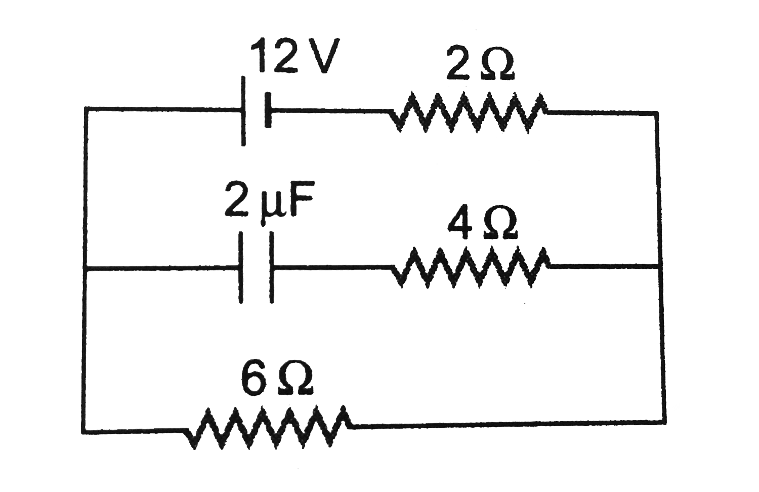
View SolutionIn the circuit shown in figure charge stored in the capacitor of capacity 5μf is

View SolutionA capacitor of 8 F is connected as shown in the figure. At steady state Charge on the plates of the capacitor
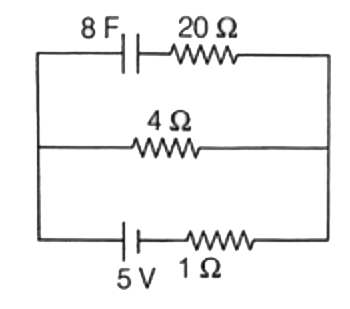
View SolutionIn the circuit shown in the figure, in steady state:
The charge on 5μF capacitor is
View SolutionThree capacitors of capacitance C1=3μf,C2=6μfandC3=10μf, are connected to a 10V battery as shown in Figure 3 below
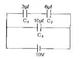
Calculate:
Equivalent capacitance
View SolutionIn the steady state of the circuit shown in the figure the ratio of energy stored in the inductor to th energy stored in the capacitor is 1000000.
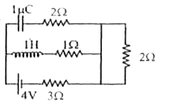
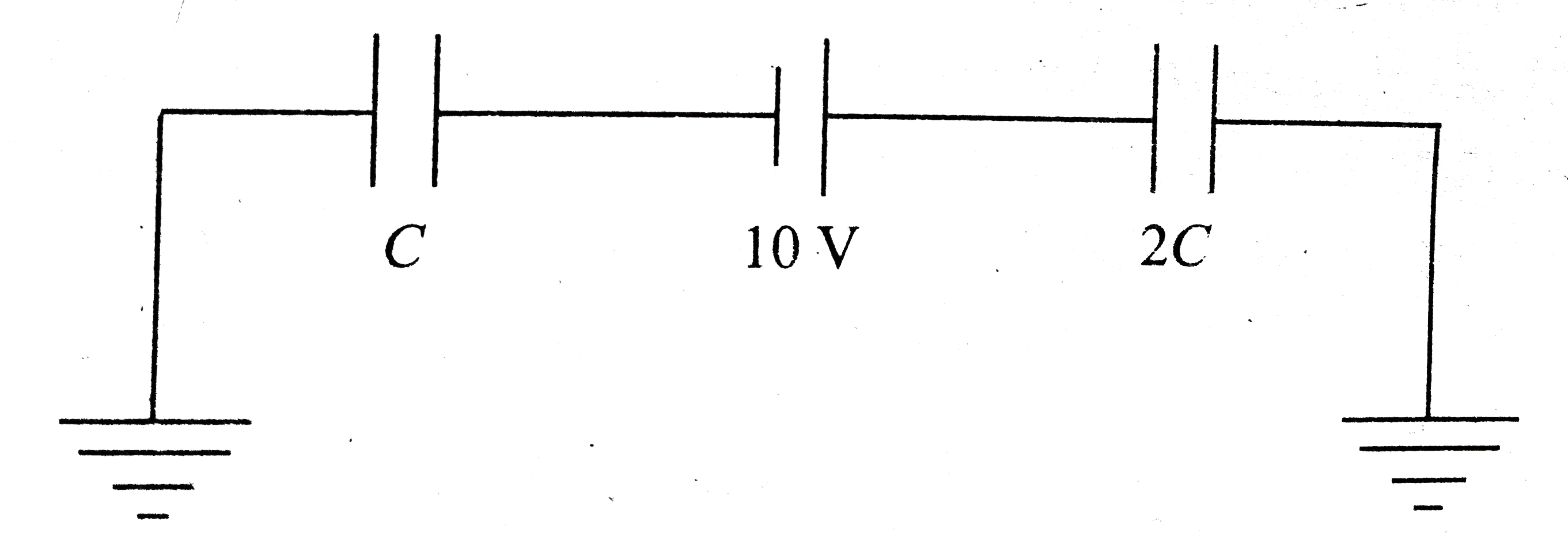
View SolutionIn the ciruit shown in, C=6μF. The charge stored in the capacitor of capacity C is
 .
.
View SolutionIn the ciruit shown in, C=6μF. The charge stored in the capacitor of capacity C is
 .
.
View SolutionIn the circuit shown in figure find
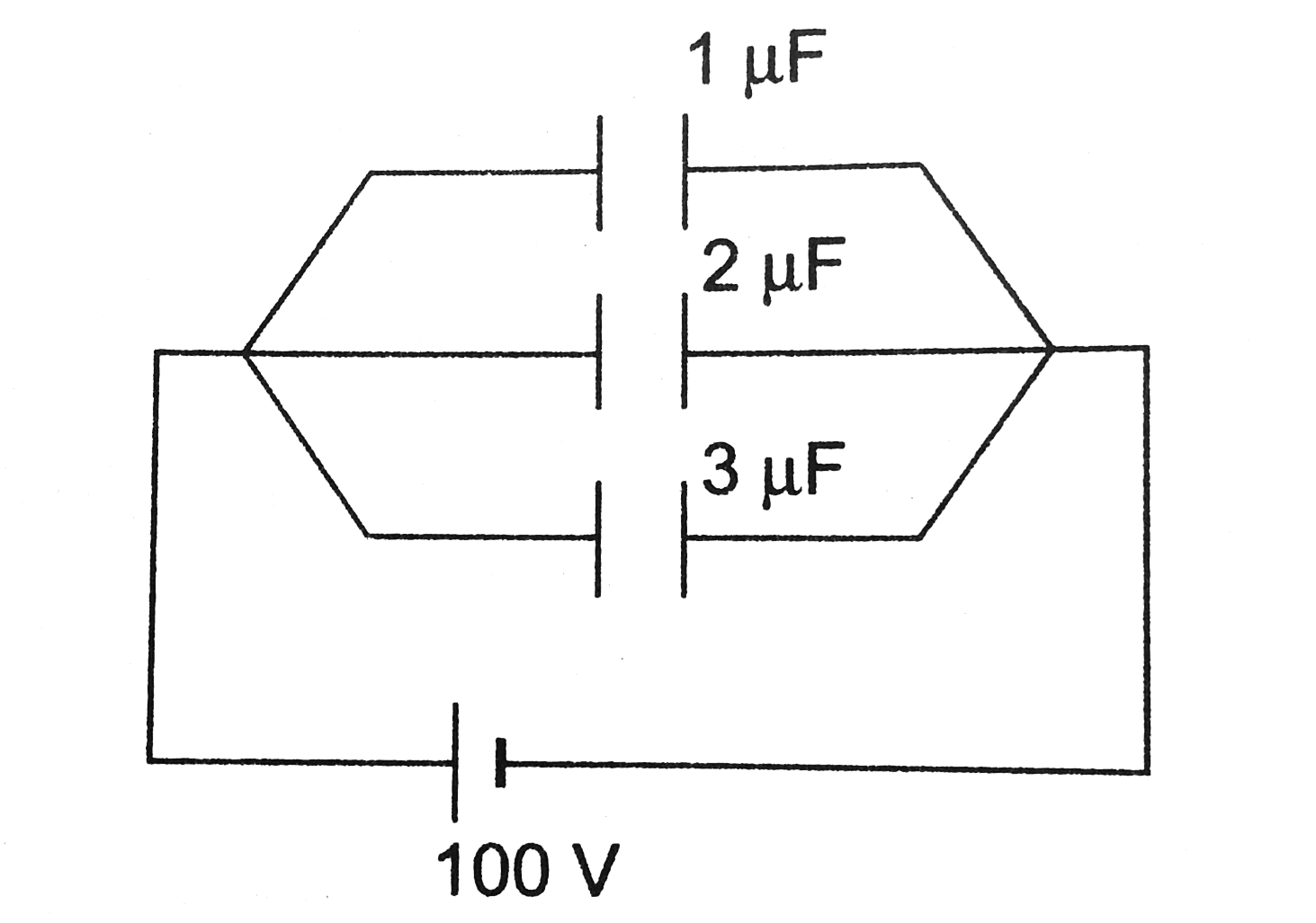
a. the equivalent capacitance and
b. the charge stored in each capacitor.
View Solution