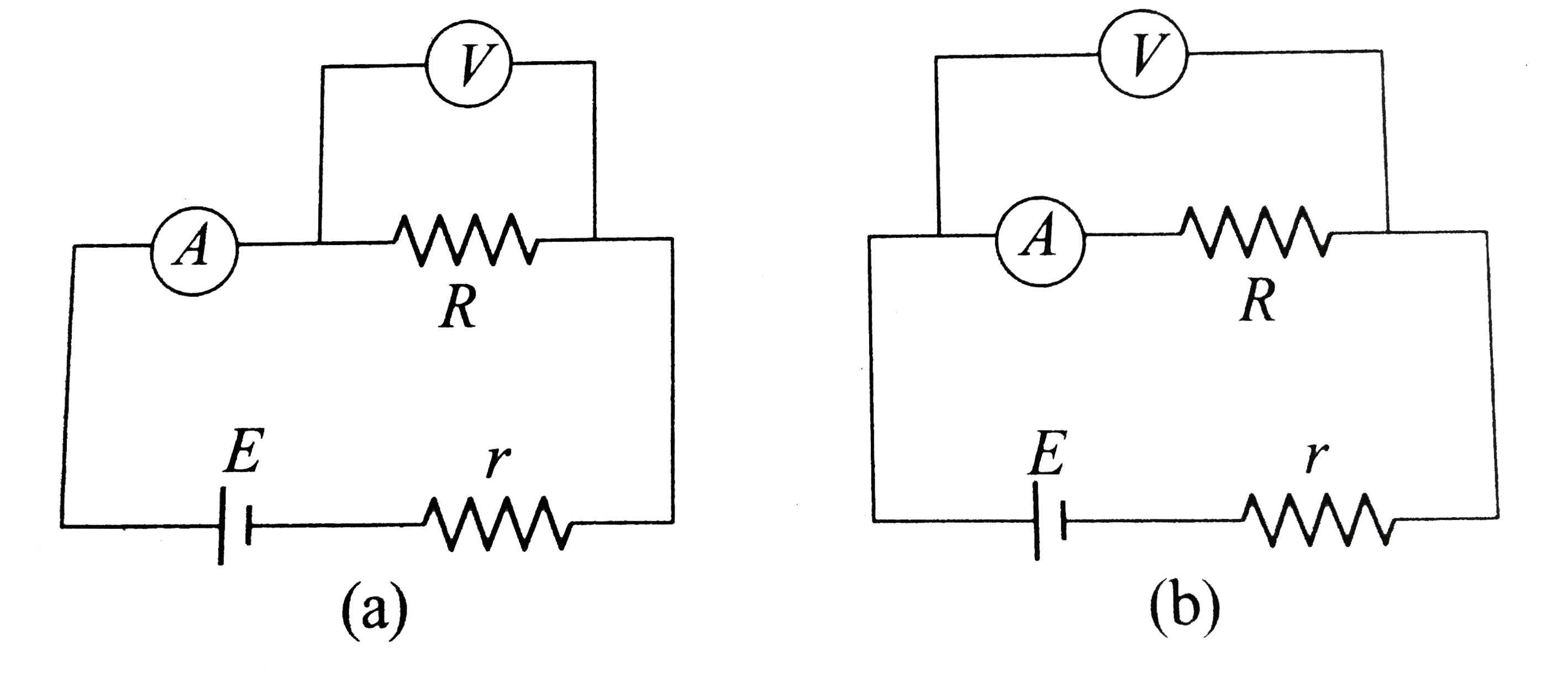
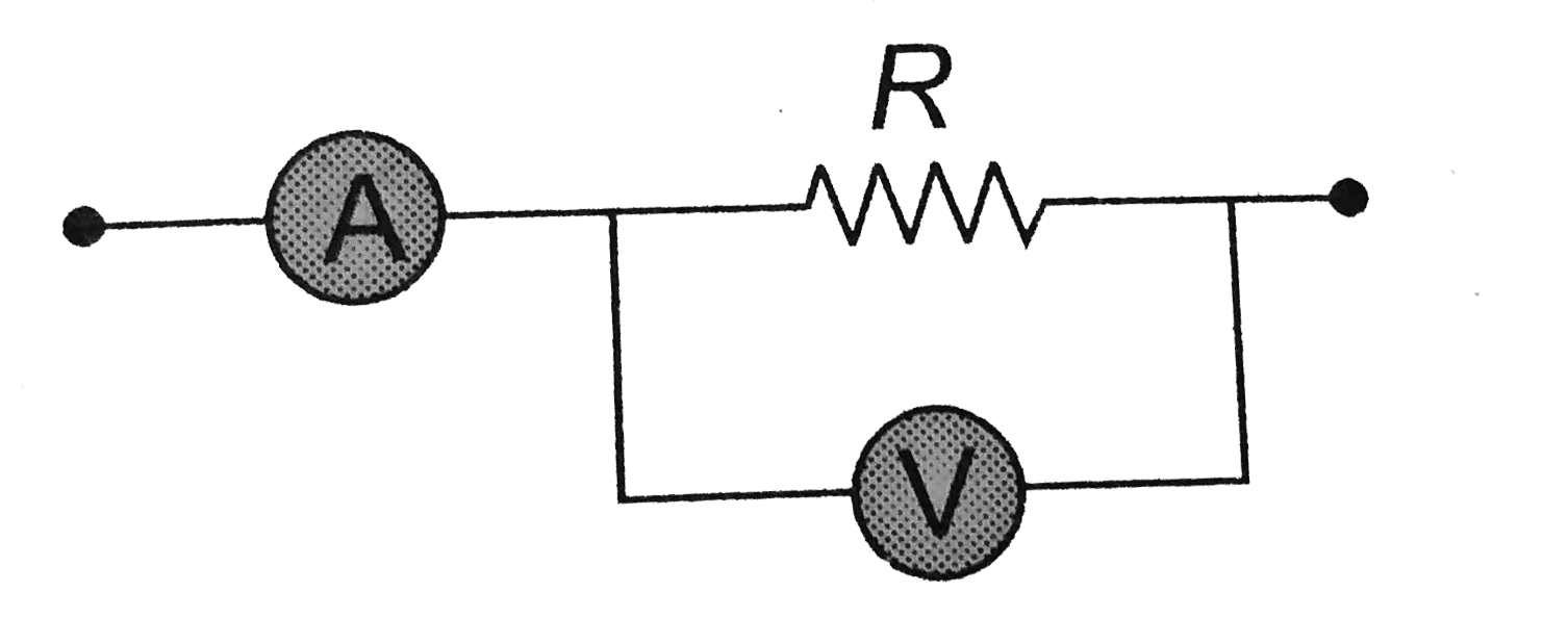
The value of resistance of an unknown resistor is calculated using the formula R=V/I where V and I are the readings of the voltmeter and the ammeter, respectivley. Consider the circuits below. The internal resistances of the voltmeter and the ammeter (RVandRG,respectively) are finite and nonzero.
 ,
,
Let RAandRB be the calculated values in the two cases A and B , respectively.
If the resistance of voltmeter is RV=1kΩ and the percentage error in the measurement of R (the value of R is nearly 10Ω)is
R>RA
R<RA
R=RA
dependent upon E and r
RA=R.RvR+Rv<R
Topper's Solved these Questions
- BOOK - VMC MODULES ENGLISHCHAPTER - DC CIRCUITEXERCISE - LEVEL-2 DAILY TUTORIAL SHEET-410videos
DC CIRCUIT
- BOOK - VMC MODULES ENGLISHCHAPTER - DC CIRCUITEXERCISE - LEVEL-2 DAILY TUTORIAL SHEET-510videos
DC CIRCUIT
- BOOK - VMC MODULES ENGLISHCHAPTER - DC CIRCUITEXERCISE - LEVEL-2 DAILY TUTORIAL SHEET-210videos
DC CIRCUIT
- BOOK - VMC MODULES ENGLISHCHAPTER - CURRENT ELECTRICITYEXERCISE - IN-CHAPTER EXERCISE-F10videos
CURRENT ELECTRICITY
- BOOK - VMC MODULES ENGLISHCHAPTER - DYNAMICS OF A PARTICLEEXERCISE - JEE Advance (Archive) Level - II (SINGLE OPTION CORRECT TYPE )31videos
DYNAMICS OF A PARTICLE
Similar Questions
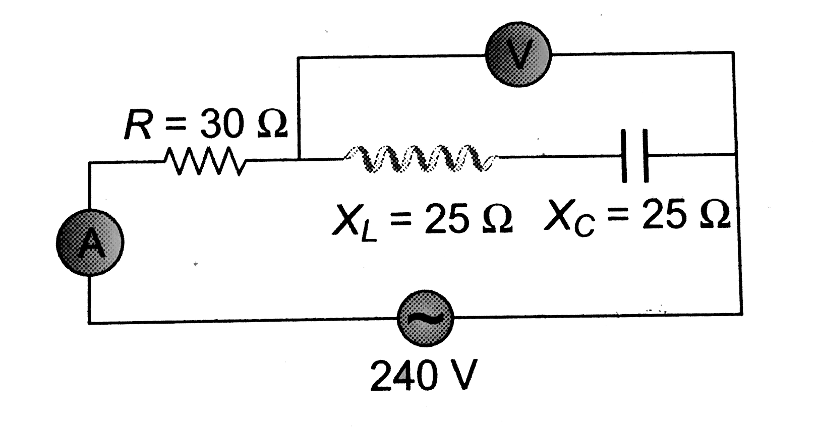
In the circuit shown in figure neglecting source resistance, the voltmeter and ammeter reading will respectively be
 View Solution
In the circuit shown in figure neglecting source resistance the voltmeter and ammeter reading will respectively, will be
 View Solution
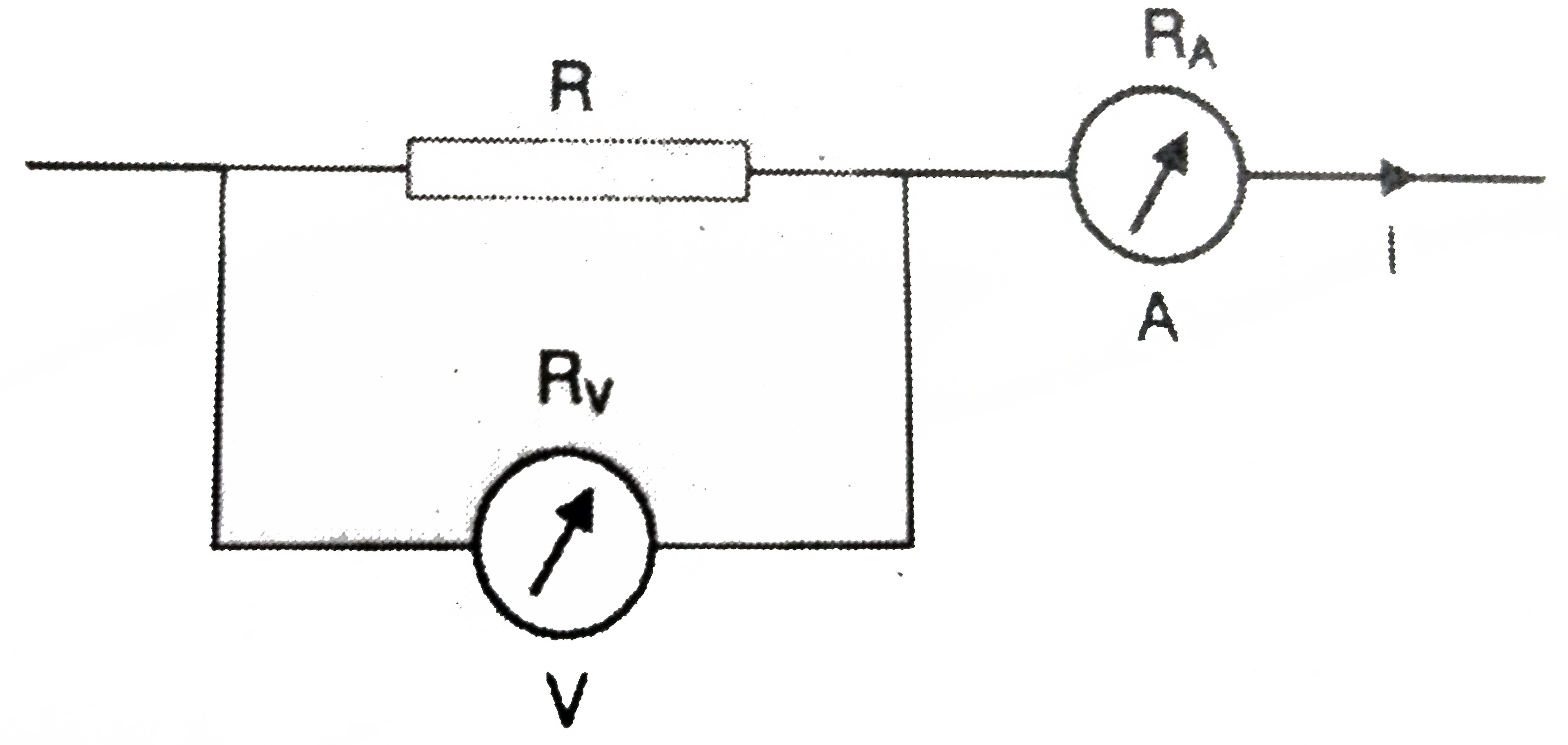
Let V and I be the readings of the voltmeter and the ammeter respectively as shown in the figure. Let RV and RA be their corresponding resistancce Therefore,
 View Solution
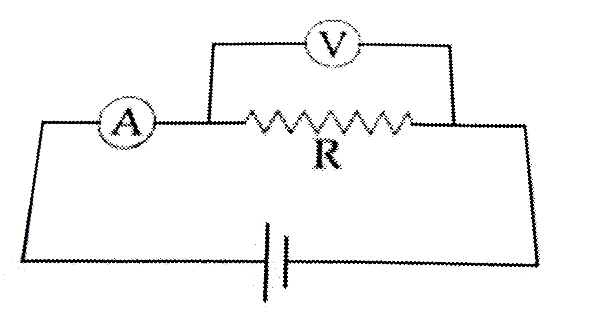
The actual value of resistance R, shown in the figure is 30Ω. This is measured in an experiment as shown using the standard formula R=VI, where V and I are the readings of the voltmeter and ammeter, respectively. If the measured value of R is 5% less, then the internal resistance of the voltmeter is
 View Solution
In the series L-C-R circuit , the voltmeter and ammeter readings are respectively
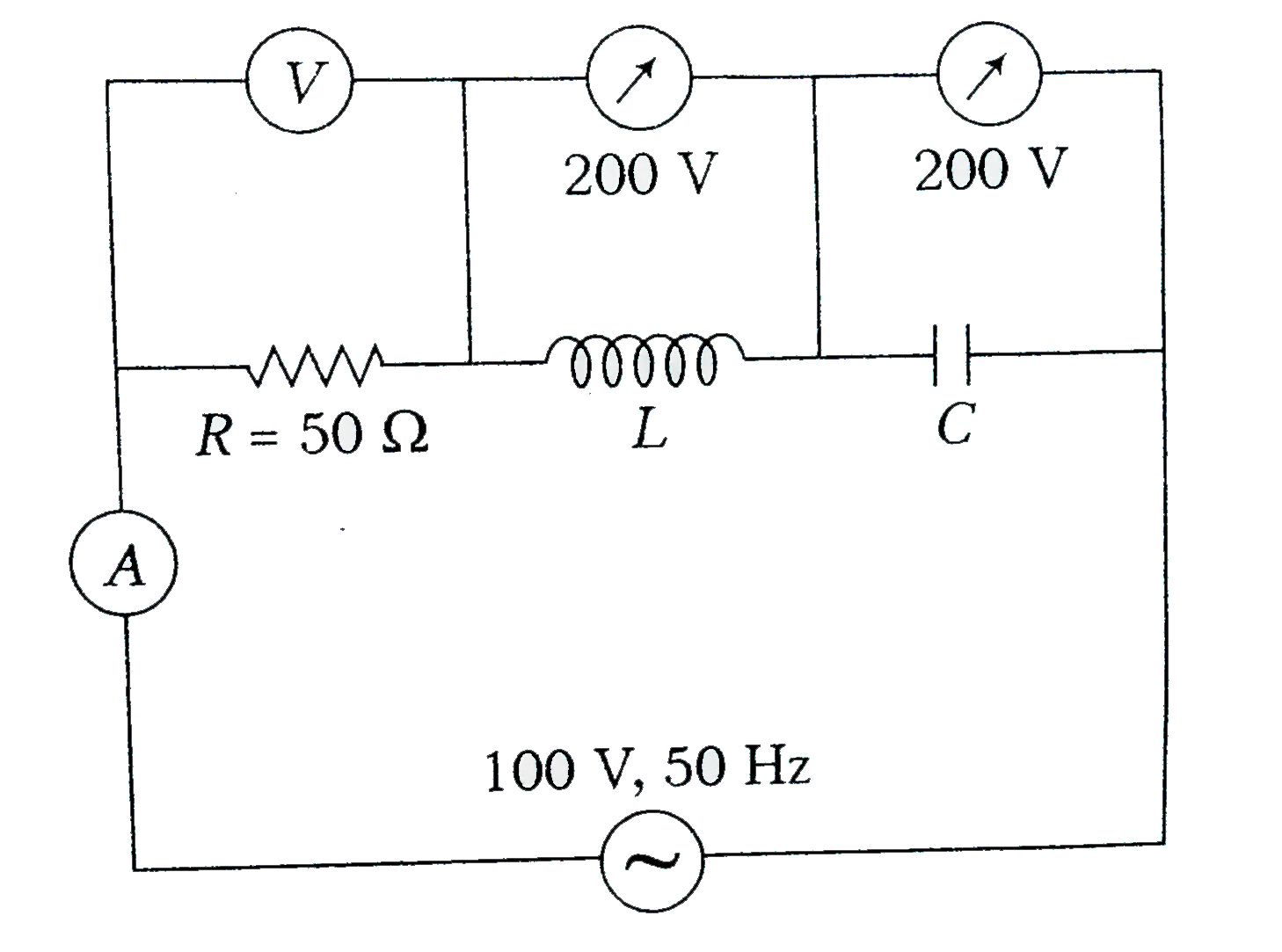 View Solution
In the series L-C-R circuit , the voltmeter and ammeter readings are
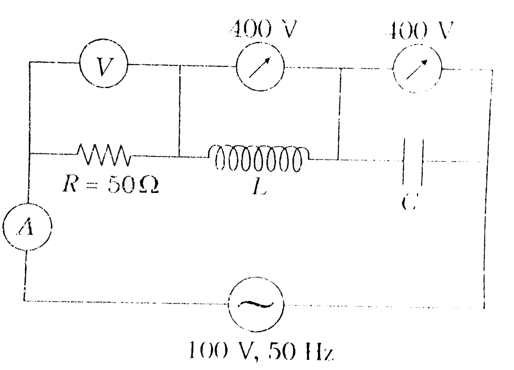 View Solution
In the series L-C-R circuit , the voltmeter and ammeter readings are
 View Solution
The ammeter A reads 2A and the voltmeter V reads 20V, the value of resistance R is (Assuming finite resistance's of ammeter and voltmeter)
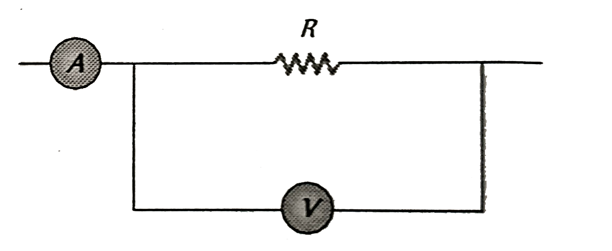 View Solution
If the resistance R1 is increased , how will the readings of the ammeter and voltmeter change?
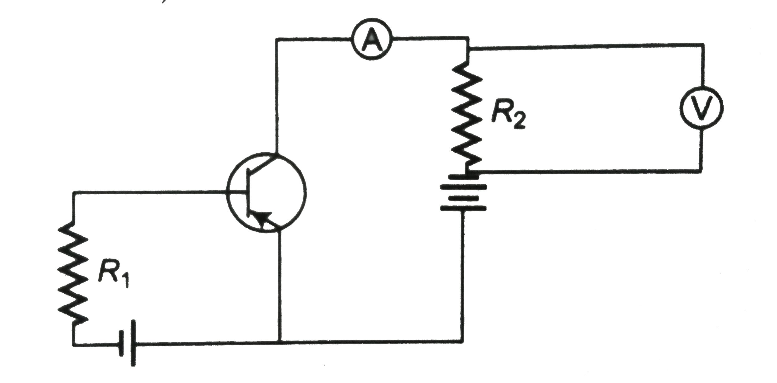 View Solution
In the circuit shown the reading of ammeter and voltmeter are 4A and 20V respectively. The meters are non ideal, then R ia
 View Solution

