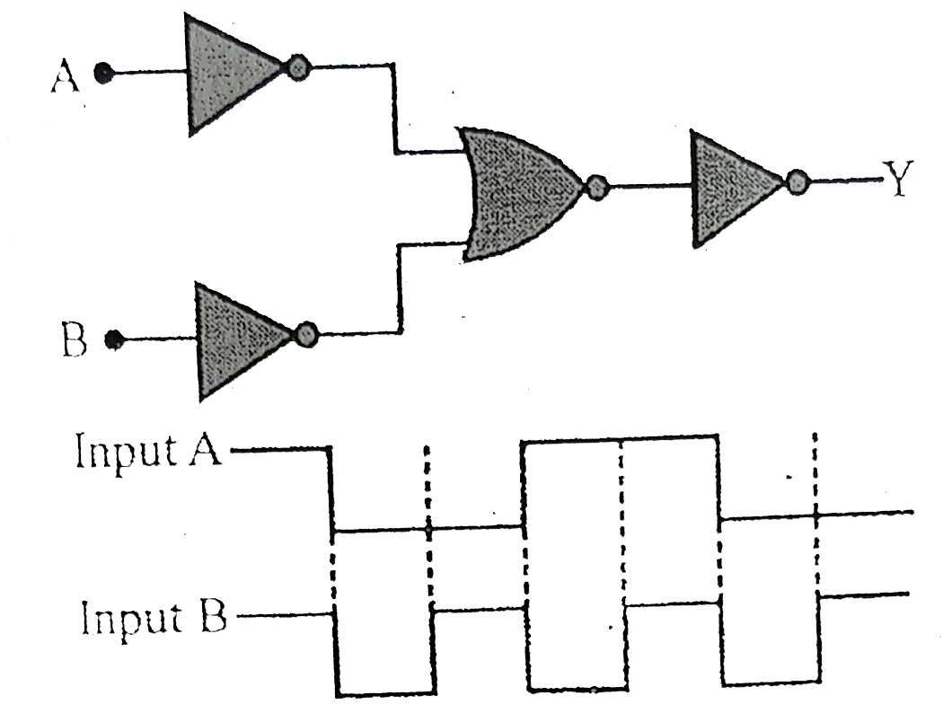
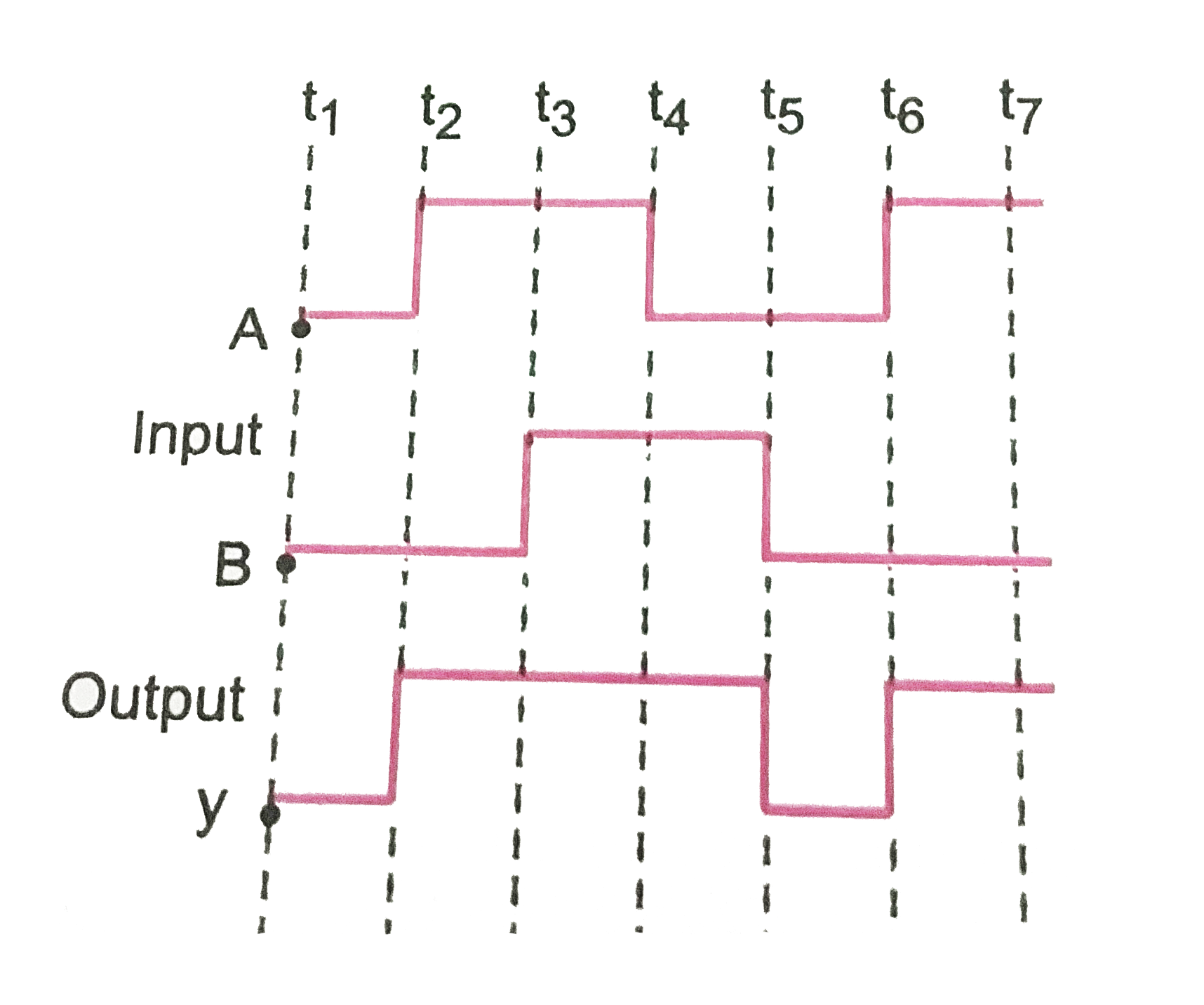
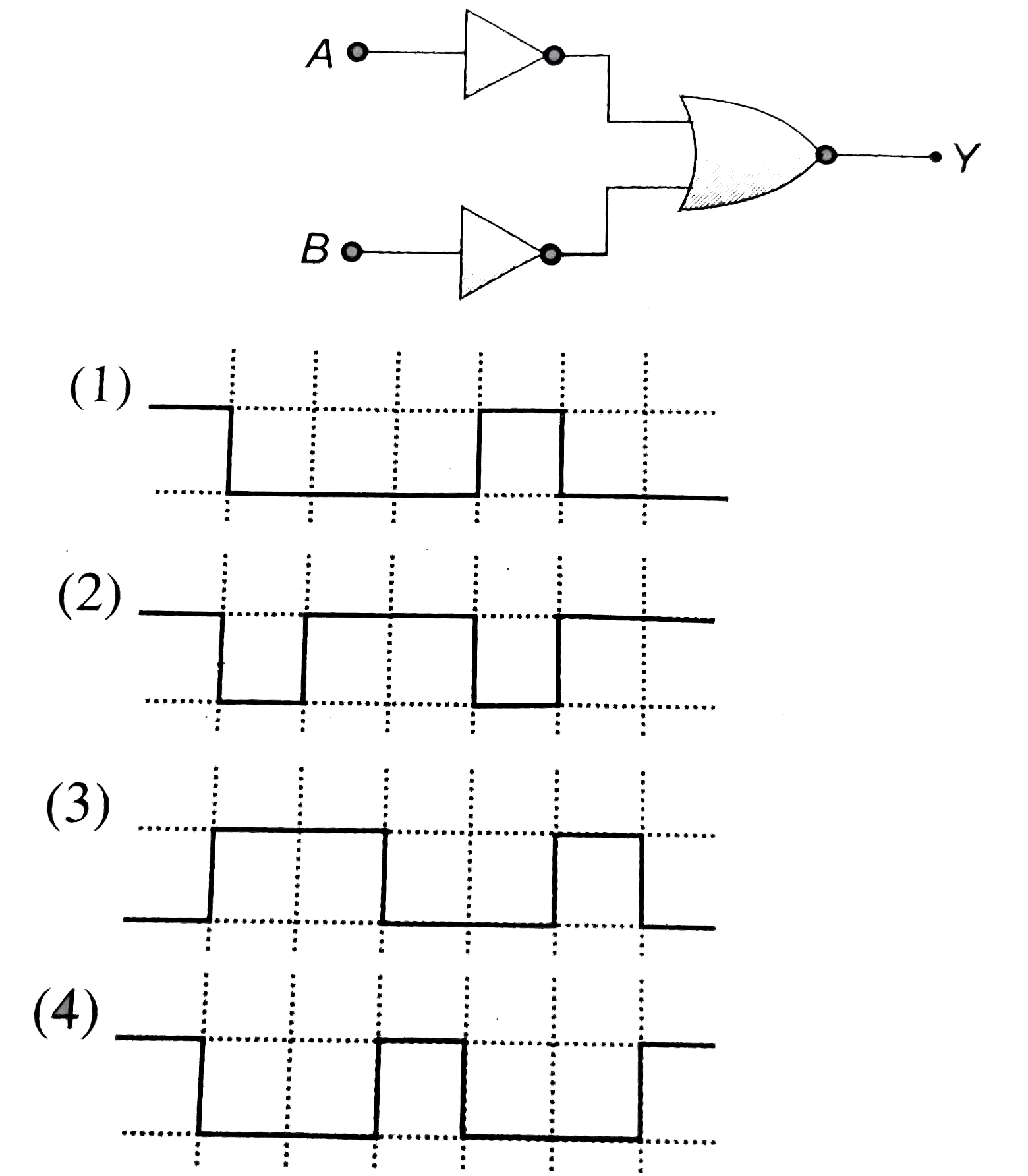
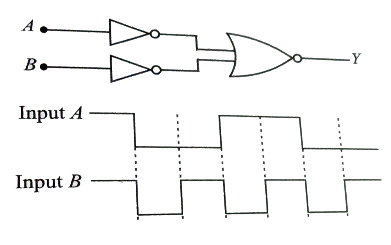
The logic circuit shown has the input waveforms 'A' and 'B' as shown. Pick out the CORRECT output waveform:-
 Solution in Gujrati


The correct Answer is:A
Output equation y=¯¯¯A+¯¯¯B=¯¯¯A.¯¯¯B
Topper's Solved these Questions
- TEST PAPERSBOOK - ALLEN CHAPTER - TEST PAPERSEXERCISE - Part-1 Physics
15 Videos
- TEST PAPERSBOOK - ALLEN CHAPTER - TEST PAPERSEXERCISE - part-2 physics
73 Videos
- TEST PAPERSBOOK - ALLEN CHAPTER - TEST PAPERSEXERCISE - PAPER 2
60 Videos
- TEST PAPER 4BOOK - ALLEN CHAPTER - TEST PAPER 4EXERCISE - PHYSICS
45 Videos
- UNIT & DIMENSIONS, BASIC MATHS AND VECTOR BOOK - ALLEN CHAPTER - UNIT & DIMENSIONS, BASIC MATHS AND VECTOR EXERCISE - Exercise (J-A)
7 Videos
Similar Questions
A quantity of 2 mole of helium gas undergoes a thermodynamic process, in which molar specific heat capacity of the gas depends on absolute temperatureT , according to relation:
C=3RT4T0
where T0 is initial temperature of gas. It is observed that when temperature is increased. volume of gas first decrease then increase. The total work done on the gas until it reaches minimum volume is :-
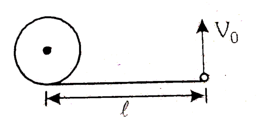
View SolutionA bead is connected with a fixed disc of radius R by an inextensible massless string in a smooth horizontal plane. If the bead is pushed with a velocity v0 prependicular to the string, the bead moves in a curve and consequently collapses on the disc. Then
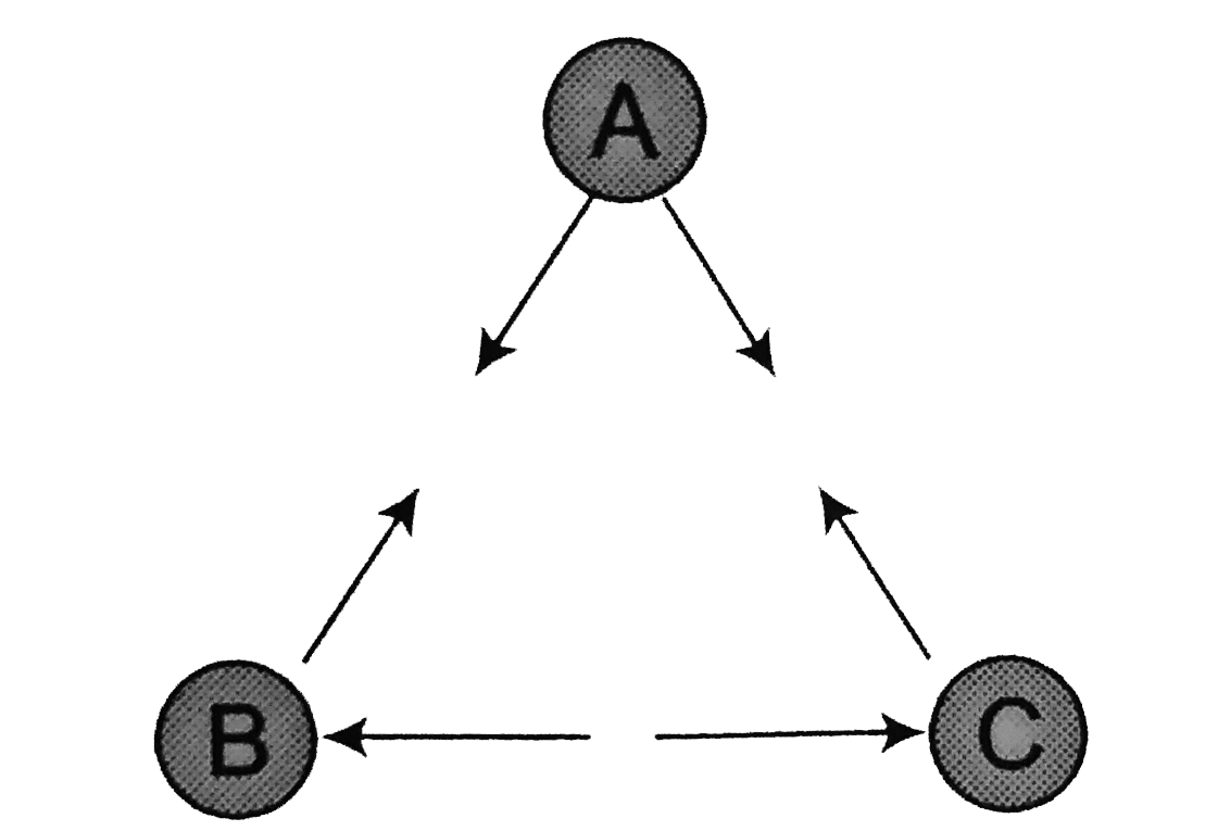
View SolutionThe diagram shows the arrangement of three small uniformally charged spheres, A,B and C. The arrow indicate the direction of the electrostatic forces acting between the spheres (for example, the left arrow on sphere A indicates the electronstatic force on sphere A due to sphere B). At least two of the spheres are positively charged. Which sphere, if any, could be negatively charged?
View SolutionTwo forces, each of magnitude F have a resultant of the same magnitude F. The angle between the two forces is
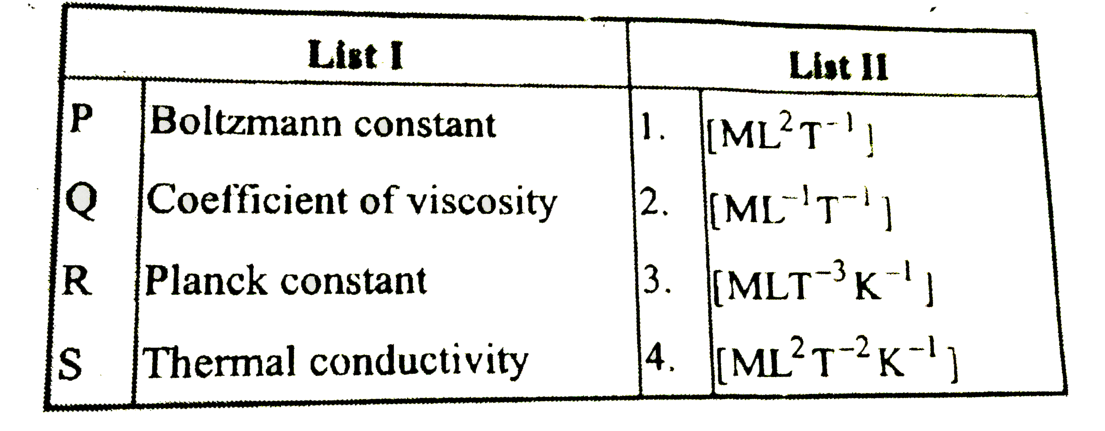
View SolutionMatch List I with List II and select the correct answer using the codes given below the lists :
View SolutionDrawn the output waveform at X, using thye given inputs A and B for the logic circuit shown in Fig. Also identify the logic operation performed by this circuit.

View SolutionThe Fig shown input waveforms A and B to a logic gate. Draw the output waveform for an OR gate. Write the truth table for this logic gate and draw its logic symbol.
View SolutionThe logic circuit shown belows has the input waveforms 'A' and 'B' as shown. Pick out the correct output waveform
View SolutionThe logic circuit shown below has the input waveforms 'A' and 'B' as shown. Pick out the correct output waveform .
View SolutionThe logic circuit shown below has the input waveform 'A' and 'B' as shown. Pick out the correct output waveform Output is :-
View SolutionThe logic circuit shown below has the input waveforms ‘A’ and ‘B’ as shown. Pick out the correct output waveform
View SolutionTwo input waveforms A and B shown in fig (a) are applied to an AND gate.Write the output waveform.
View SolutionThe logic circuit shown below has the inputs waveforms A and B as shown. Pick out the correct output waveform.
View SolutionThe following figure shows a logic gate circuit with two inputs A and B and the output C. The voltage waveforms of A, B and C are as shown below.
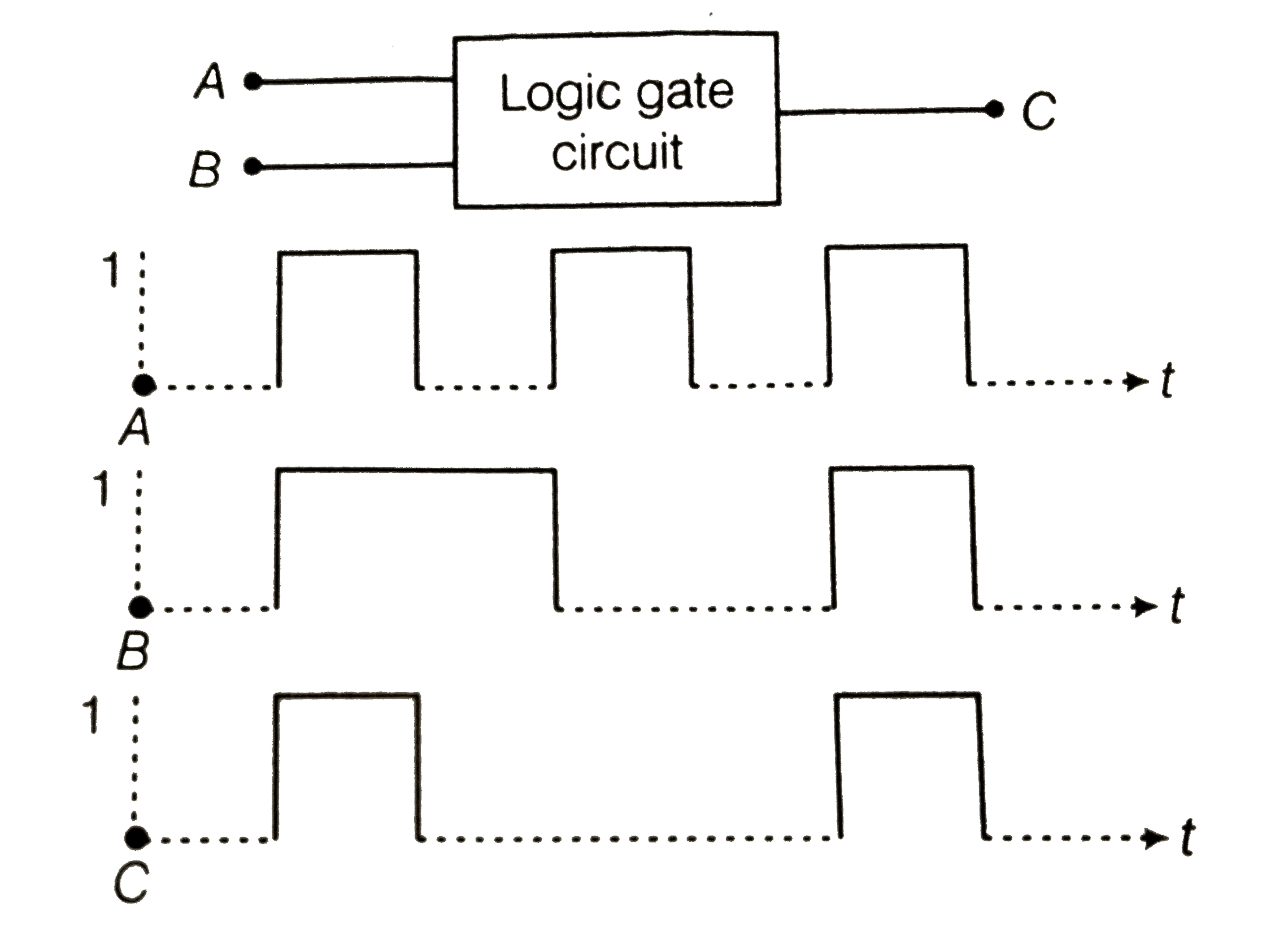
The logic circuit gate is
View SolutionThe following figure showns a AND logic gate circuit with two inputs A and B and the output C. The voltage waveforms at C will be -
View SolutionThe logic circuit shown below has the input waveform 'A' and 'B' as shown . Pick out the correct output waveform .
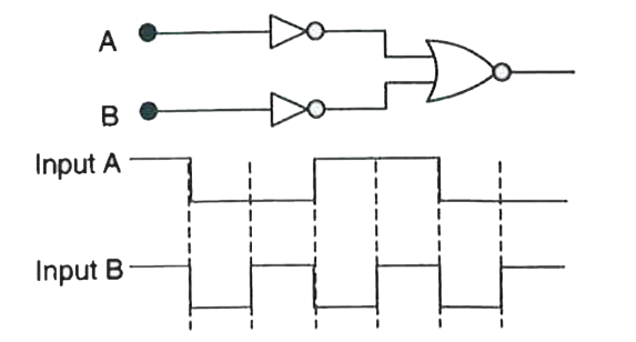
output is :
View Solution
