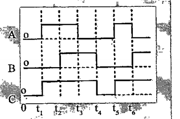
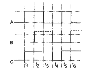
The figure show a logic circuit with inputs A and B and the output C.The voltage waves forms across A, B and C are given .The logic circuit gats is :
 Solution in Tamil
NOR gate
AND gate
NAND gate
OR gate
Step by step video & image solution for The figure show a logic circuit with inputs A and B and the output C.The voltage waves forms across A, B and C are given .The logic circuit gats is : by Physics experts to help you in doubts & scoring excellent marks in Class 12 exams.
Updated on:21/07/2023Topper's Solved these Questions
Similar Questions
The electric and magnetic field of an electromagnetic wave are :
View SolutionThree points charges +q,-2q and +q are placed at points (x=0,y=a,z=0),(x=0,y=0,z=0)and (x=a,y=0,z=0) respectively.The magnitude and direction of the electric dipole moment vector of this charge assembly are .
View SolutionThe figure shows a logic circuit with two inputs A and B and the output C. The voltage wave forms across A,B and C are as given. The logic circuit gate is
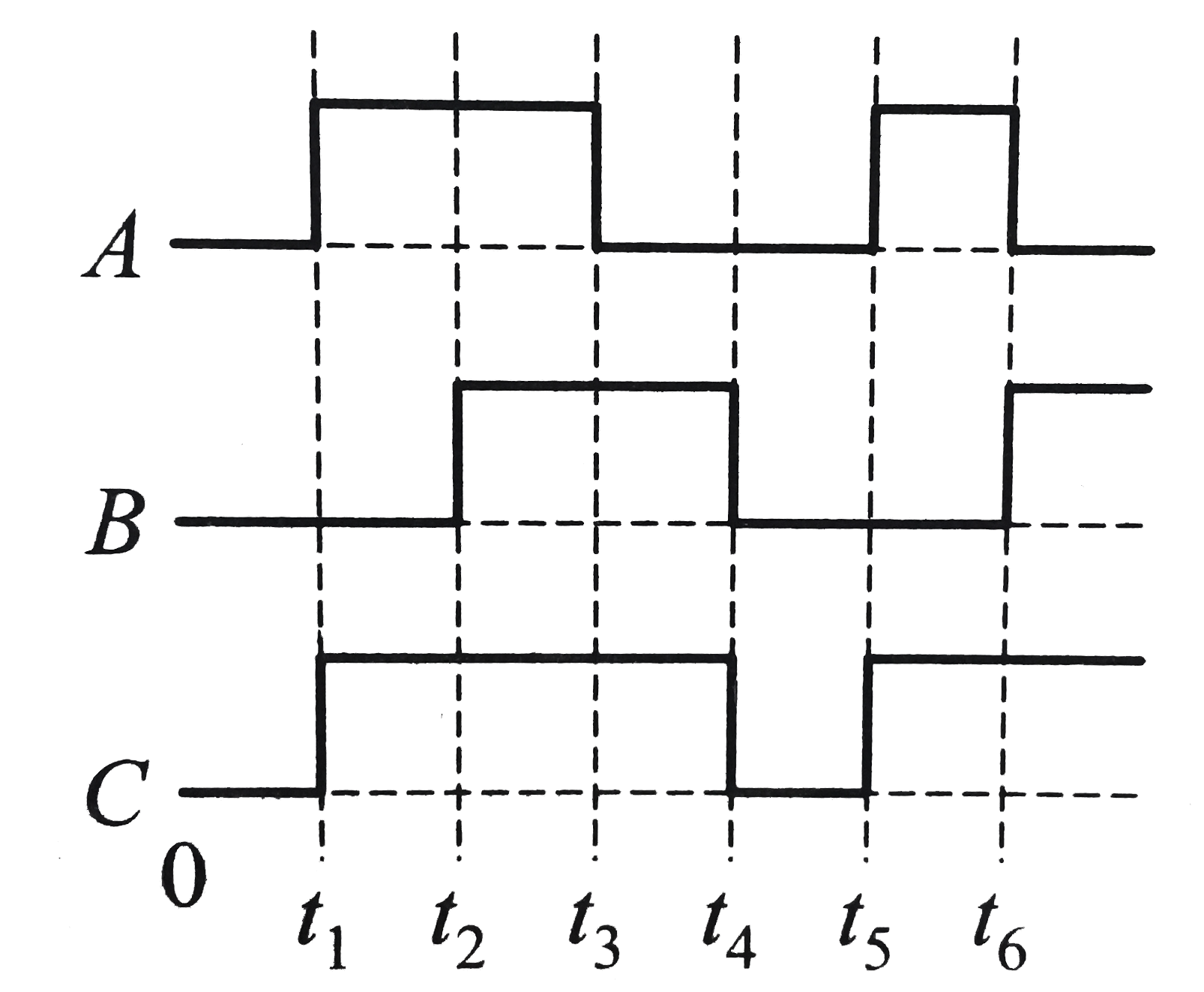
View SolutionFig, shows a logic gate circuit with two input A and B and the output C. The voltage wave form of A, B and C are as shown in Fig.The logic gate circuit is
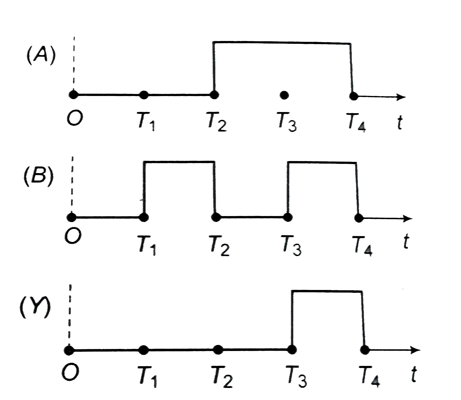
View SolutionThe given figure shows the wave forms for two inputs A and B and that for the output Y of a logic circuit.the logic circuit is
View SolutionThe following figure shows a logic gate circuit with two inputs A and B output C. The voltage waveforms of A,B and C are as shown in second figure given below :-
_E01_436_Q01.png)
The logic circuit gate is :-
View SolutionThe following figure shows a logic gate circuit with two inputs A and B and the output C. The voltage waveforms of A, B and C are as shown below.
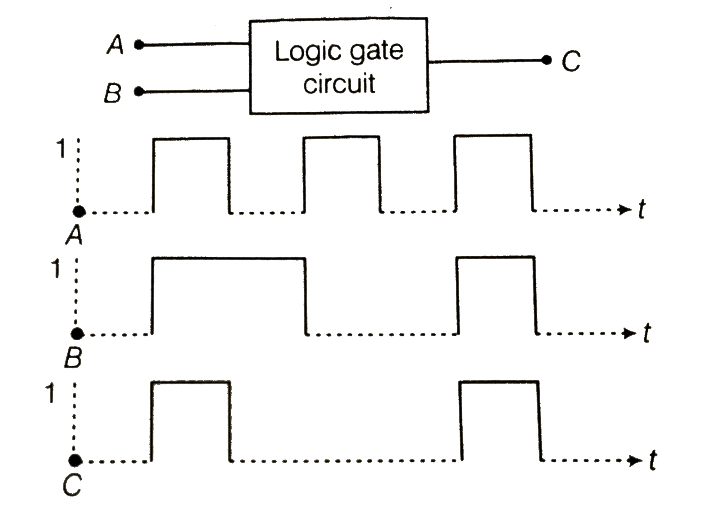
The logic circuit gate is
View Solutionचित्र में एक लॉजिक परिपथ में दो निवेशी A तथा B और एक निर्गत C दर्शाया गया है| A,B तथा C के वोलटता तरंगरूप दिए गए अनुसार है| तब लॉजिक परिपथ गेट है-
View Solutionनिम्नलिखित चित्र में एक तर्क द्वार परिपथ को दिखाया गया है जिसमें दो निवेश A और B और एक निर्गत हैं। A,B और C के वोल्टता तरंग-रूप निम्न प्रकार हैं
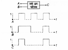
यह तर्क परिपथ द्वार है
View SolutionThe following shows a logic gate circuit with two inputs A and B and the output C. The voltage waveforms of A, B and C are as shown below.
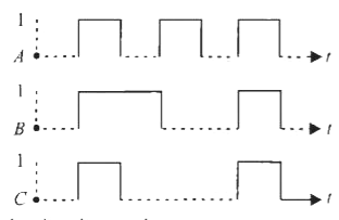
The logic circuit gate is
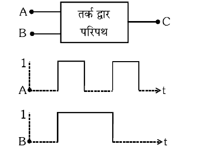
View Solutionनिम्नलिखित चित्र में एक AND तर्क द्वार परिपथ को दिखाया गया है जिसमें दो निवेश A और B और एक निर्गत C हैं। C की वोल्टता का तरंग-रूप निम्न प्रकार होगा
View SolutionThe figure shows the voltage waveforms across two inputs A and B and the output Y of a logic circuit. The logic circuit gate is
View SolutionThe figure shows a logic circuit with two inputs A and B and the output C. The voltage wave forms across A,B and C are as given. The logic circuit gate is

View SolutionThe figure shows a logic circuit with two inputs A and B and the output C. The voltage wave forms across A,B and C are as given. The logic circuit gate is

View SolutionThe following figure shows a logic gate circuit with two inputs A and B output C. The voltage waveforms of A,B and C are as shown in second figure given below :-
_E01_436_Q01.png)
The logic circuit gate is :-
View SolutionThe following figure shows a logic gate circuit with two inputs A and B and the output C. The voltage waveforms of A, B and C are as given The logic circuit is:
View Solution
