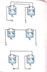
Three students (A),(B) and ( C) connected their two resistor R1 and R2 in the manner shown below.

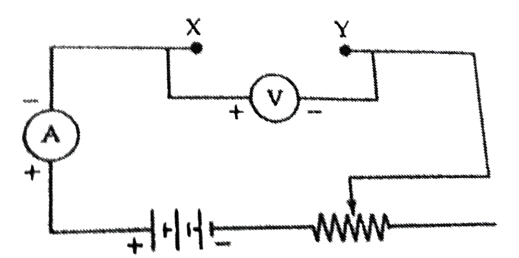
They connected the terminals marked X and Y above to the two terminals marked X and Y in the circuit given below:

They record the ammeter readings for different positions of teh rheostate and the corresponding voltmeter readings. The average value of the ratio V/I in thier observations would be minimum for:Solution in Punjabi
Students A and B only
Students B and C only
Students C and A only
Students A only
Step by step video & image solution for Three students (A),(B) and ( C) connected their two resistor R_1 and R_2 in the manner shown below.They connected the terminals marked X and Y above to the two terminals marked X and Y in the circuit given below:They record the ammeter readings for different positions of teh rheostate and the corresponding voltmeter readings. The average value of the ratio V/I in thier observations would be minimum for: by Physics experts to help you in doubts & scoring excellent marks in Class 10 exams.
Updated on:21/07/2023Topper's Solved these Questions
Similar Questions
Define electric current and give its unit
View SolutionWrite the S.I. unit of magnetic field →B.
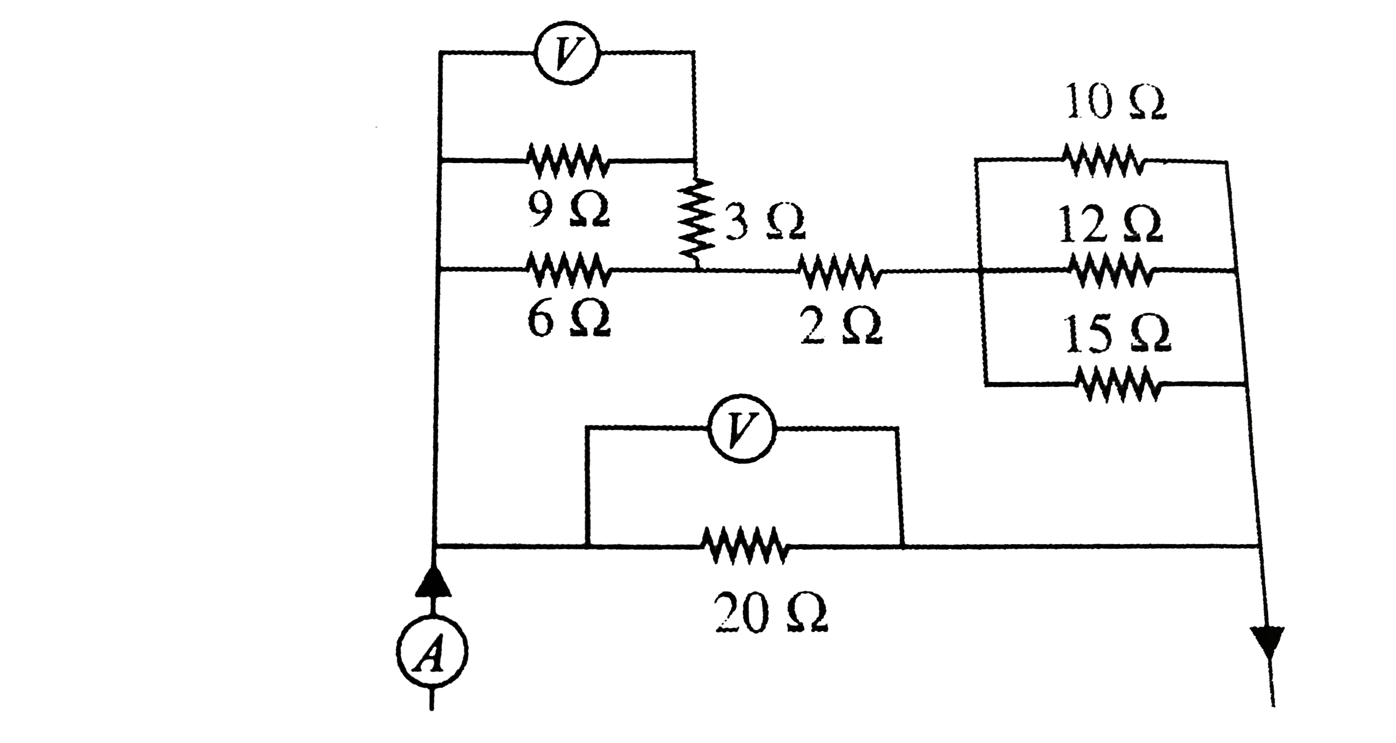
View SolutionShown two ideal voltmeters and an ammeter, which are connected across the various circuit elements. If the voltmeter connected across 9Ω resistance reads 4.5 V, then answer the following problems.

The reading of the voltmeter connected across 20Ω resistance is
View SolutionTo the terminals marked as X and Y in the given circuit, three students connect 4 cells of voltage 1.5 V each in three different manners (A),(B), (C) shown in (Fig. 3.62). Find the readings (V_A, V_B, V_C) of the voltmeter, for the three students. .
View SolutionIn the experiment on finding the equivalent resistance of two resistors connected in series, three students connected the ammeter in their circuits in the three ways X, Y and Z shown here.

Assuming their ammeters to be ideal, the ammeters have been correctly connected in
View SolutionIn the experiment on finding the equivalent resistance of two resistors, connected in parallel, three students connected the voltmeter in their circuits, in the three ways X, Y and Z shown here. The voltmeter has been correctly connected in
View SolutionFor three circuits, shown here the same two resistors R_(1) and R_(2) have been connected in parallel in all the circuits but the voltmeter and the ammeter have been connected in three different positions. The relation between the three voltmeter and ammeter readings would be :
View SolutionTwo students (A) and (B) connect their two given resistors R1 and R2 in the menners shown below :

Student (A) connects the terminals marked (b1) and (C1) while student (B) connects the terminals marked (d2) and (c2) in their respective circuits at the points marked X and Y.

Which one of the following is correct in relation to above arrangements ?
View SolutionThree students (A), (B) and (C) connect their two given resistors R_(1) and R_(2) in the manners shown below : They connect the terminals marked X and Y above to the terminals marked X and Y in the circuit given below: The record the Ammeter readings (I) for different positions of the rheostat and the corresponding Voltmeter readings (V). The average value of the ratio V/I in their observations would be minimum for :
View SolutionThe values of resistance marked on the coils R1 and R2 are found to be correct. A student connects the given resistors in the following manner (as shown in Figure 1).

He then connects the terminals marked X and Y of the above combination of resistors R1 and R2 to the terminals marked X and Y in the circuit (shown in Figure 2).
The average value of the ratio V/I in the obervations recorded in the circuit would be :
View SolutionA student connects a voltmeters, ammeter and resistance according to the circuit given. If the voltmeter reading is 20V and ammeter reading is 4A, then the resistance will be

View SolutionAn ammeter, voltmeter and a resistor are connected in series to a cell and the readings are noted as I and V. If another resistor R is connected in parallel with a voltmeter, then
View SolutionDraw the diagram of the electric circuit in which the resistors R_1, R_2 and R_3 are connected in series including ammeter and voltmeter and mark the direction of current .
View SolutionDraw the diagram of an electric circuit in which the resistors R1,R2andR3 are connected in parallel including an ammeter and a voltmeter and mark the direction of the current.
View SolutionDraw the diagram of an electric circuit in which the resistors R1,R2andR3 are connected in parallel including an ammeter and a voltmeter and mark the direction of the current.
View SolutionWhat do a voltmeter connected to two terminals of a cell read: the emf or the terminal potential difference?
View Solution
