To study the dependence of current on the potential difference across a resistor, two set ups shown in fig. A and B respectively. They kept the contact in different positions marked (1), (2), (3), (4) in the two figures.
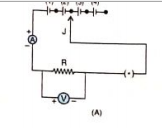

For the two students thier ammeter and voltmeter readings will be minimum when the contact J is in the positionsSolution in Punjabi
(1) both the set ups
(4) in both the set ups
(4) in set ups (A) and (1) set up (B)
(1) in set up (A) and (4) in set up(B)
Step by step video & image solution for To study the dependence of current on the potential difference across a resistor, two set ups shown in fig. A and B respectively. They kept the contact in different positions marked (1), (2), (3), (4) in the two figures.For the two students thier ammeter and voltmeter readings will be minimum when the contact J is in the positions by Physics experts to help you in doubts & scoring excellent marks in Class 10 exams.
Updated on:21/07/2023Topper's Solved these Questions
Similar Questions
Define electric current and give its unit
View SolutionWrite the S.I. unit of magnetic field →B.
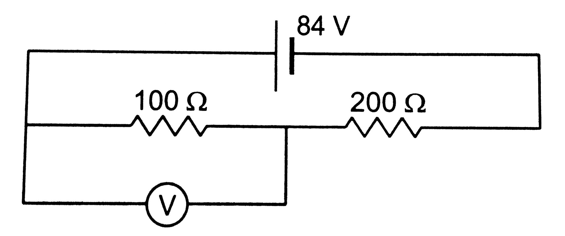
View SolutionA voltmeter of resistances 400(Ω)is used to measure the potential difference across the 100(Ω)resistor in the circuit shown in figure.(a) What will be the reading of the voltmeter ?(b) What was the potential difference across 100(Ω)before the voltmeter was connected ?
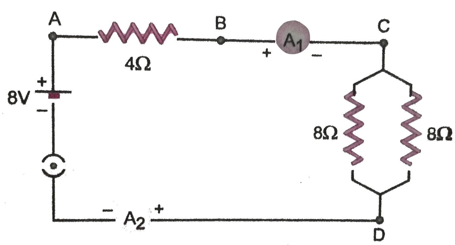
View SolutionFind out the folowing in the electric circuit given in (Fig.
(a) Effective resistance of two 8Ω resistors in the combination
(b) Current flowing through 4Ω resistor
( c) Potential difference across 4Ω resistance
(d) Power dissipated in 4Ω resistor
(e) Difference in ammeter readings, if any.
 .
.
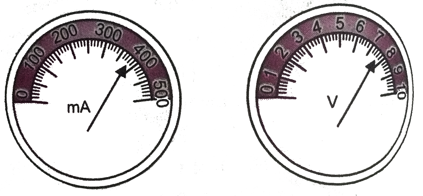
View SolutionThe current flowing through a conductor and the potential difference across its two ends are as per reading of the ammeter and the voltmeter shown in (Fig. 3.50). Find the resistance of the conductor.
 .
.
View SolutionTo study the dependence of current (I) on the potential difference (V) across a resistor, the correct way of connecting the ammeter and voltmeter in the circuit is :
View SolutionTo study the dependence of current (I) on the potential difference (V) across a resistor R, two students used the two set ups shown in Figures A and B respectively. They kept the contact point J in four different positions, marked (a), (b), (c) and (d) in the two figures.

For the two students, the ammeter and voltmeter readings will be maximum when the contact J is in the position :
View SolutionTo study the dependence of current (I) on the potential difference (V) across a resistor, two students used the two sets ups shown in figs (A) and (B) respectively. They kept the contact J in four different positions, marked (a), (b), (c), (d) in the two figures.
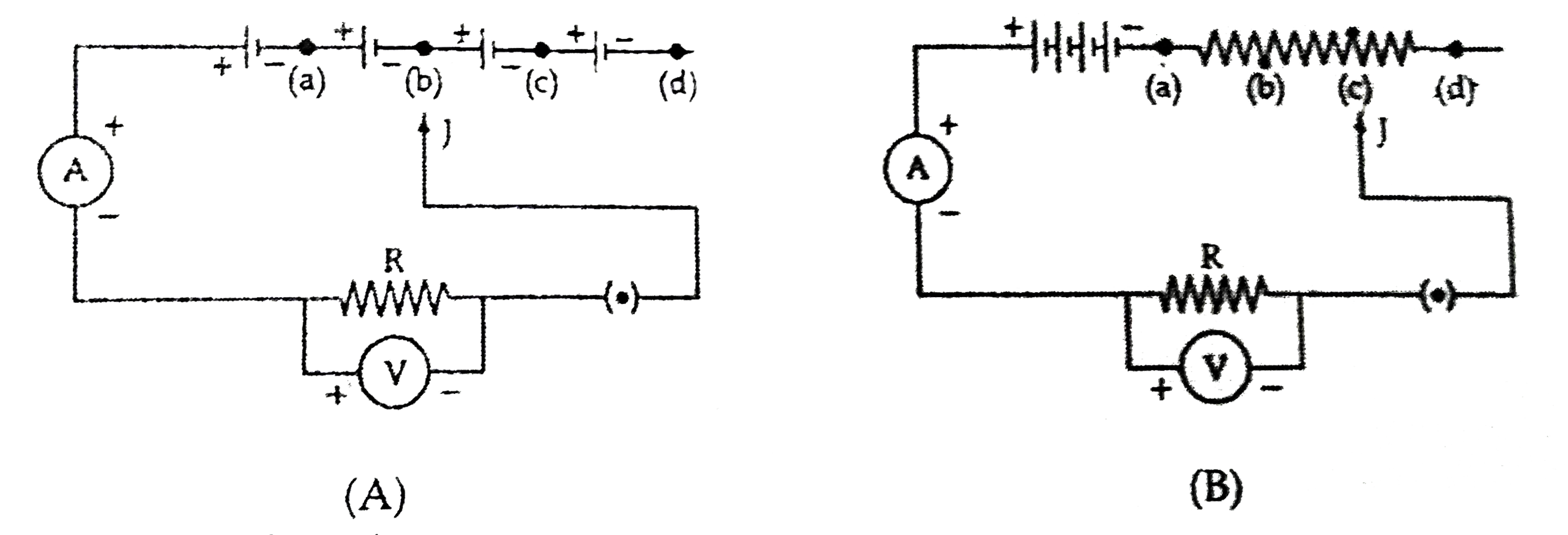
For the two students, their Ammeter and Voltmeter readings will be minimum when the contact J is in the position :
View SolutionA student using the same two resistors, ammeter, voltmeter and battery, sets up two circuits A and B connecting the two resistors first in series and then in parallel.
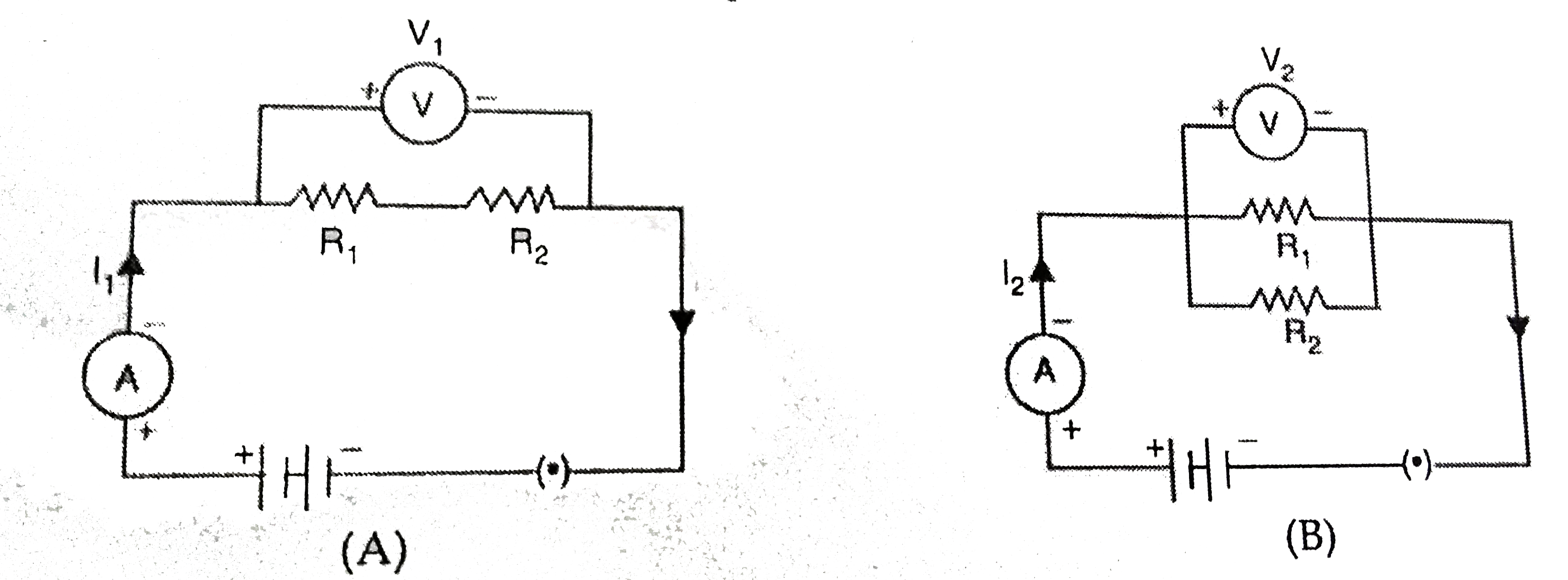
If the ammeter and voltmeter readings in the two cases be I1,I2 and V1,V2 respectively, he is likely to observe that :
View SolutionRedraw the circuit of question 1, putting in an ammeter to measure the current through the resistors and a voltmeter to measure potential difference across the 12 Ω resistor. What would be the readings in the ammeter and the voltmeter?
View SolutionRedraw the circuit of Question 1, putting in an ammeter to measure to current through the resistors and a voltmeter to measure the potential difference across the 12Ω resistor. What would be the readings in the ammeter and the voltmeter?
View SolutionFind out the folowing in the electric circuit given in (Fig. 3.48). (a) Effective resistance of two 8 Omega resistors in the combination (b) Current flowing through 4 Omega resistor ( c) Potential difference across 4 Omega resistance (d) Power dissipated in 4 Omega resistor (e) Difference in ammeter readings, if any. .
View SolutionWhich of the following is the correct set-up for studying the dependence of the current on the potential difference across a resistor and why?
View SolutionRedraw the circuit of 9.39, putting in an ammeter to measure the current through the resistors and a voltmeter to measure the potential difference across the 12Omega resistor. What would be the readings in the ammeter and the voltmeter ?
View SolutionOut of the four circuits shown,for studying the dependence of current on the potential difference across a resistor,the correct circuit is
View SolutionRedraw the circuit, putting in an ammeter to measure the current through the resistors and a voltmeter to measure the potential difference across the 12Ω resistor. What would be the readings in the ammeter and the voltmeter?
View Solution
