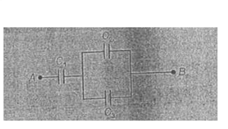
चित्र में प्रदर्शित संधारित्र c2में विभवांतर व संचित ऊर्जा की गणना कीजिये। बिंदु A पर विभव 90 V है। c1=20μF,c2=30μFऔर c3=15μFहै।

Step by step video & image solution for चित्र में प्रदर्शित संधारित्र c_(2)में विभवांतर व संचित ऊर्जा की गणना कीजिये। बिंदु A पर विभव 90 V है। c_(1) =20 mu F ,c_(2) =30 muF और c_(3) = 15 mu F है। by Physics experts to help you in doubts & scoring excellent marks in Class 12 exams.
Updated on:21/07/2023Topper's Solved these Questions
- इंटरमीडिएट परीक्षा 2018 BOOK - UP BOARD PREVIOUS YEARCHAPTER - इंटरमीडिएट परीक्षा 2018 EXERCISE - भौतिक विज्ञान 373 (FW)
28 Videos
- इंटरमीडिएट परीक्षा 2018 BOOK - UP BOARD PREVIOUS YEARCHAPTER - इंटरमीडिएट परीक्षा 2018 EXERCISE - भौतिक विज्ञान 372 (FQ)
28 Videos
- इंटरमीडिएट परीक्षा 2018 BOOK - UP BOARD PREVIOUS YEARCHAPTER - इंटरमीडिएट परीक्षा 2018 EXERCISE - भौतिक विज्ञान 373 (FV)
28 Videos
- अर्द्धचालक इलेक्ट्रॉनिकी पदार्थ , युक्तियाँ तथा सरल परिपथ BOOK - UP BOARD PREVIOUS YEARCHAPTER - अर्द्धचालक इलेक्ट्रॉनिकी पदार्थ , युक्तियाँ तथा सरल परिपथ EXERCISE - विस्तृत उत्तीय प्रश्नोत्तर ?
52 Videos
- इण्टरमीडिएट परीक्षा, 2013BOOK - UP BOARD PREVIOUS YEARCHAPTER - इण्टरमीडिएट परीक्षा, 2013EXERCISE - भौतिक विज्ञान - द्वितीय प्रश्न - पत्र (373(IH))
23 Videos
Similar Questions
UHF परिसर की आवृतियो का प्रसारण प्रायः किस प्रकार की तरंगो द्वारा होता है।
View Solutionवैद्युत क्षेत्र→E में →p आघूर्ण वाले द्विध्रुव पर लगने वाला बल आघूर्ण है - शून्य
View Solutionवस्तु की अपेक्षा बड़ा आभासी प्रतिबिम्ब बनाने दर्पण है -
View Solutionऊर्जा बैण्ड के आधार पर चालक,अचालक एवं अर्द्धचालकों का वर्गीकरण स्पष्ट कीजिए।
View Solutionवैद्युत क्षेत्र की तीव्रता का मात्रक है
View SolutionIn fig. C1=20μF,C2=30μFandC3=15μF and the insulated plate of C1 is at a potential of 90 V, one plate of C3 being earthed. What is the potential difference between the plates of C2 three capacitors being connected in series ?
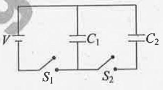
View SolutionConsider the circuit shown where C1=6μF,C2=3μF and V=20V. Capacitor C1 is first charged by closing the switch S1. Switch S1 is then opened, and the charged capacitor is connected to the uncharged capacitor C2 by closing S2.

View SolutionA combination arrangement of the capacitors is shown in the figure
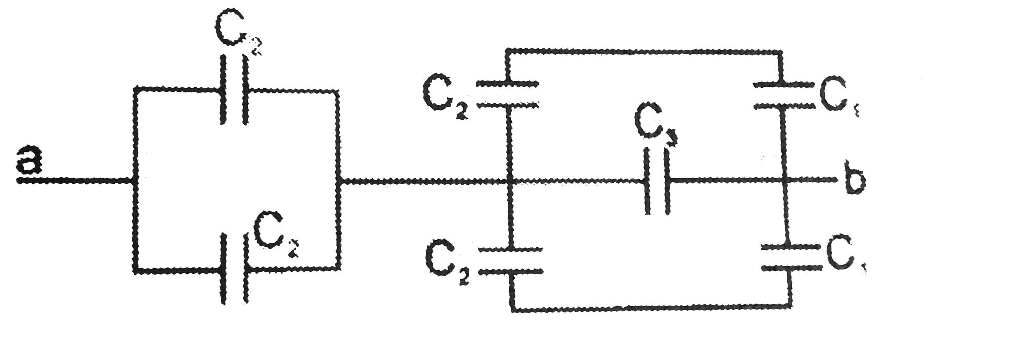
(i) C1=3μF,C2=6μF and C3=2μF then equivalent capacitance between 'a' and 'b' is :

View SolutionA capacitor C_(1) =1.0 muF F is charged up to a voltage V=60 V by connecting it to battery B through switch (1) Now C_(1) is disconnected from battery and connected to a circuit consisting of two uncharged capaictors C_(2)=3.0 mu F and C_(3)=6.0 mu F through switch (2) as shown in the figure The sum of final charges on C_(2) and c_(3) is :
View Solutionचित्र में प्रदर्शित संधारित्र C2 में विभवान्तर व संचित ऊर्जा की गणना कीजिए । बिंदु A पर विभव 90 V है।
C1=20μF,C2=30μF और C3=15

View SolutionC3वC_(4)चक्र में क्या अन्तर है? समझाइये।
View Solutionआवेशित चालक की ऊर्जा | संधारित्र में संचित ऊर्जा
View SolutionIn the arrangement C1=10μ,FC2=10μF and C3=20μF . What is the equivalent capacitance ( in μF ) between points A and B ?

View SolutionCapacitors C_(1)(10 mu F) and C_(2) (20 mu F) are connected in series across a 3 kV supply, as shown. What is the charge on the capacitor C_(1) ?
View SolutionIn the circuit shown below C_(1) = 10 mu"F, " C_(2) = C_(3) = 20 mu F, and C_(4) = 40 mu F. if the charge on C_(1) is 20 mu C then potential difference between X and Y is
View SolutionA part of the circuit is AB as shown. E=10 V C_(1)=1.0 mu F,C_(2)=2.0 muF And voltage V_(A)-V_(B)=5 V is C_(1) There is potential at the ends of: -
View Solution
