A circuit containing a two position switch S is shown in figure
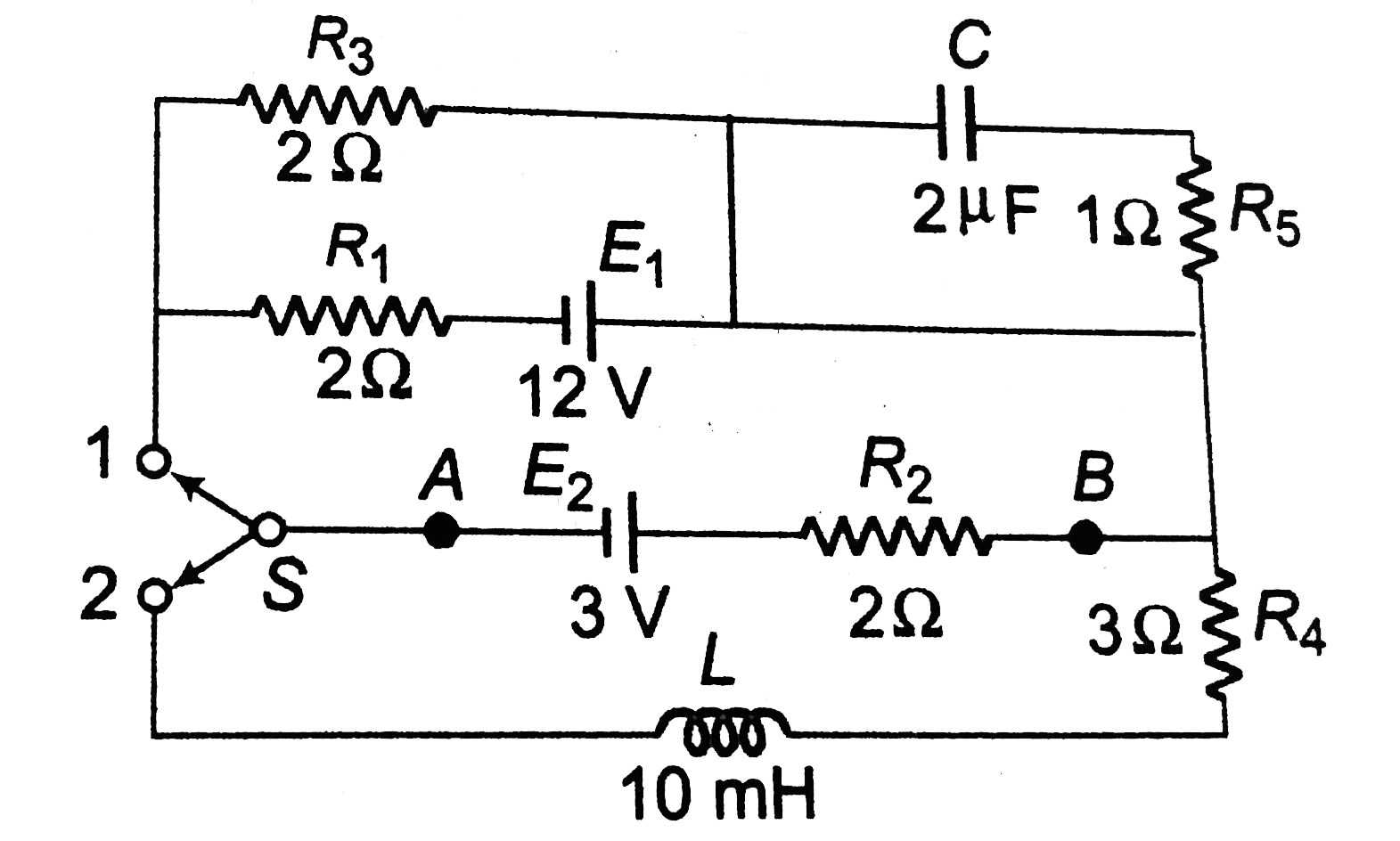
a. The switch S is in position 1. Find the potential differecne VA−VB and the rte of production of joule heat in R1
b. If now the switch S is put in position 2 at t=0. Find ltbRrgt i steady current in R4 and ii hte time when current in R4 is half the steady value. Also calculate the energy stored in the inductor L at that time.
a. In steady state no current will flow through capacitor.

Applying kirchoff's second law in loop 1.
−2i2+2(i1−i2)+12=0
∴2i1−4i2=−12
or i1−2i2=−6……i
Applying Kirchoff's second law in loop 2,
−12−2(i1−i2)+3−2i2=0
∴4i1−2i2=−9 ..(ii)
Solving Eqn i and ii we get
i2=2.5A and i1=−1A
Now VA+3−2i1=VB or VA−VB=2i1−3
=2(−1)−3=−5V
PR1=(i1−i2)2R1=(−1−2.5)2(2)
=24.5W
b. In position 2 Circuit is as below
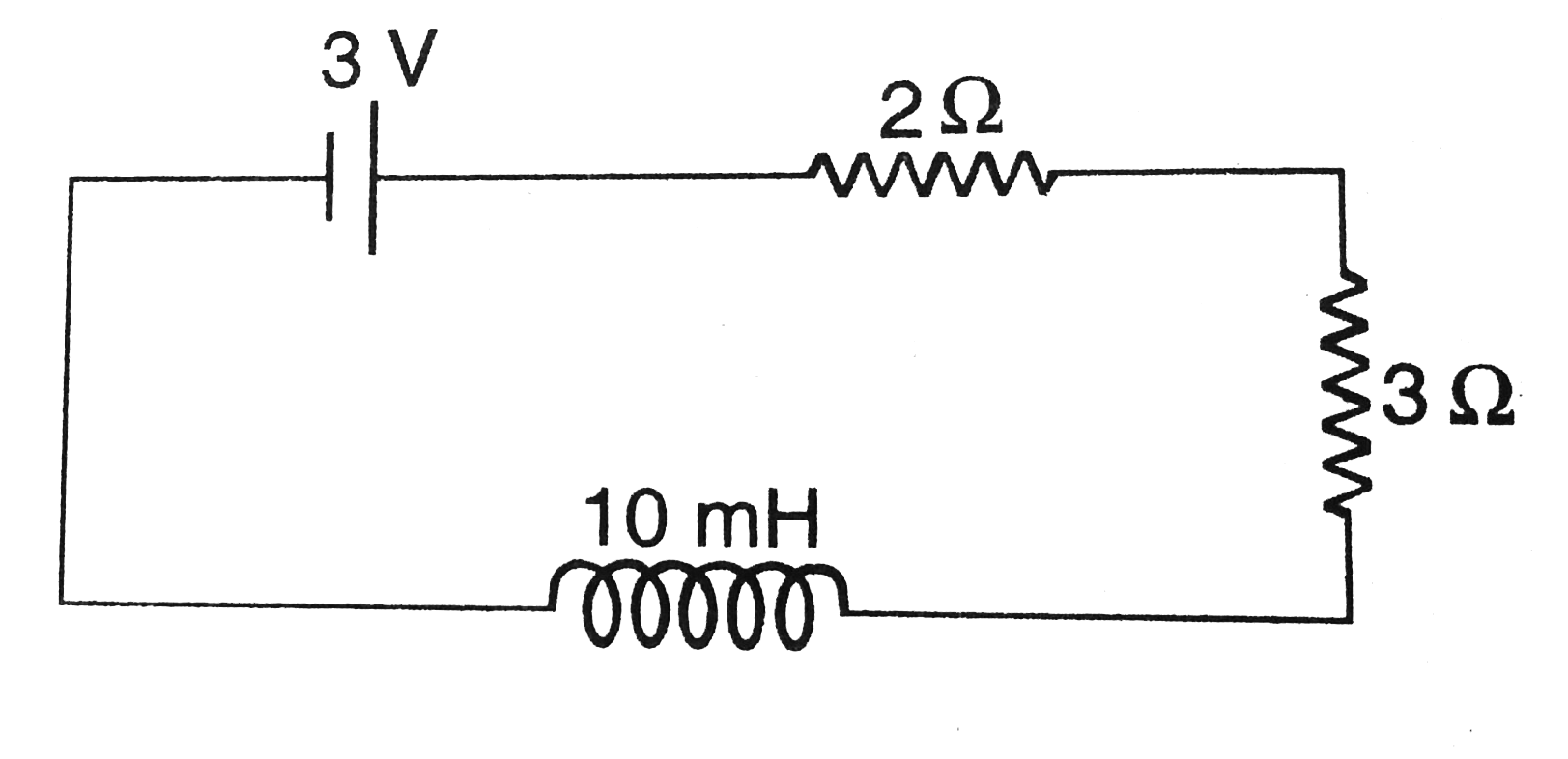
Steady current in R4
i0=33+2=0.6a
Time when current in R4 is half the steady value,
i=i0(1−e−t/τL)
i=i02att=t12, where
t1/2=τL(In2)=LRIn(2)=(10×10−3)5In(2)
=1.386x1210x10−3s
U=12Li2=12(10×10−3)(0.3)2
=4.5×10⁻⁴J
Topper's Solved these Questions
- ELECTROMAGNETIC INDUCTIONBOOK - DC PANDEY ENGLISHCHAPTER - ELECTROMAGNETIC INDUCTIONEXERCISE - Example Type 4
2 Videos
- ELECTROMAGNETIC INDUCTIONBOOK - DC PANDEY ENGLISHCHAPTER - ELECTROMAGNETIC INDUCTIONEXERCISE - Example Type 5
2 Videos
- ELECTROMAGNETIC INDUCTIONBOOK - DC PANDEY ENGLISHCHAPTER - ELECTROMAGNETIC INDUCTIONEXERCISE - Example Type 2
2 Videos
- CURRENT ELECTRICITYBOOK - DC PANDEY ENGLISHCHAPTER - CURRENT ELECTRICITYEXERCISE - Medical entrances gallery
97 Videos
- ELECTROMAGNETIC WAVESBOOK - DC PANDEY ENGLISHCHAPTER - ELECTROMAGNETIC WAVESEXERCISE - Sec C
22 Videos
Similar Questions
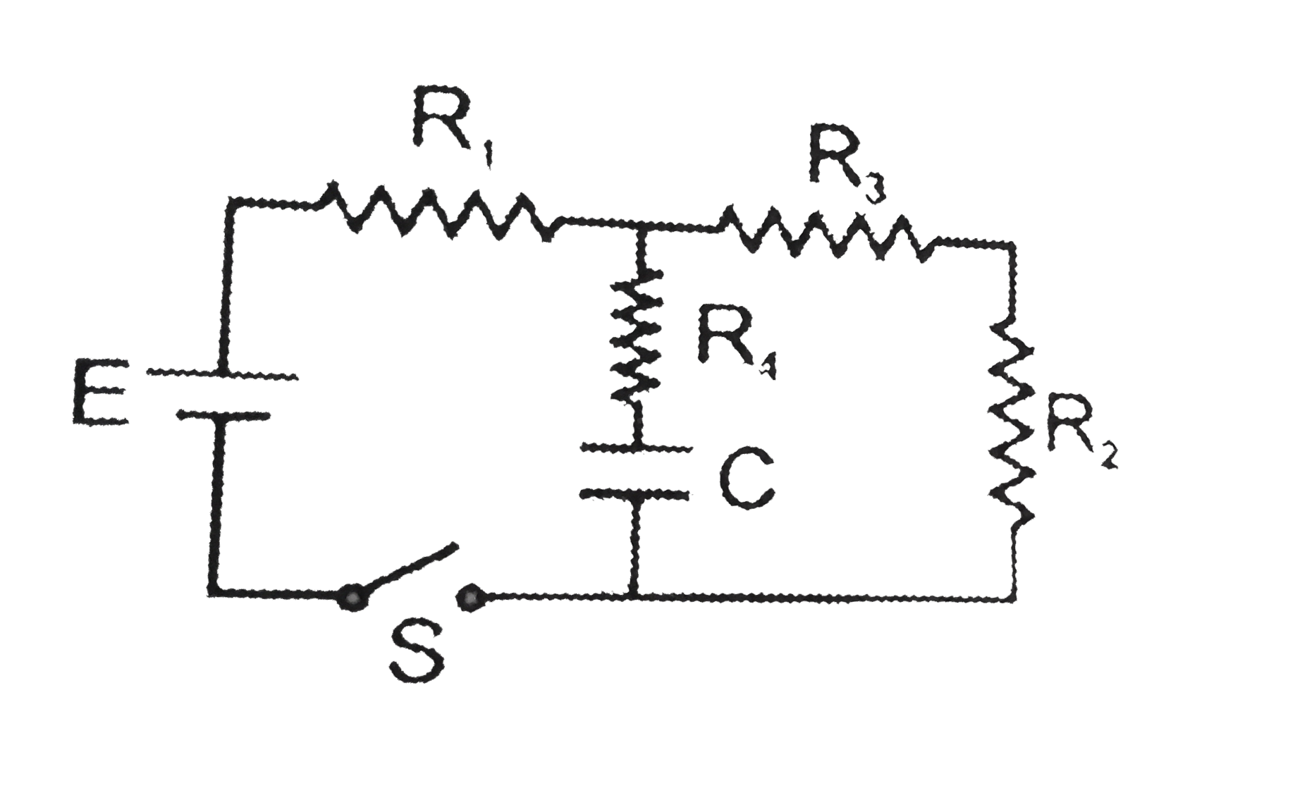
In the circuit shown in figure the switch S is closed at t = 0. A long time after closing the switch
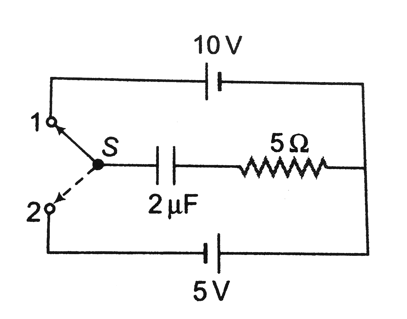
View SolutionIn the circuit given in fig. swithc S is at position 1 for long time. Find the total heat generated in resistor of resistance (2r0), when the switch S is shifted from position 1 to position 2.

View SolutionIn the circuit shown in figure switch S is thrown to position 1 at t=0. when the current in the resistort is 1A, it is shifted to position 2. the total heat generated in the circuit after shifting to position 2 is
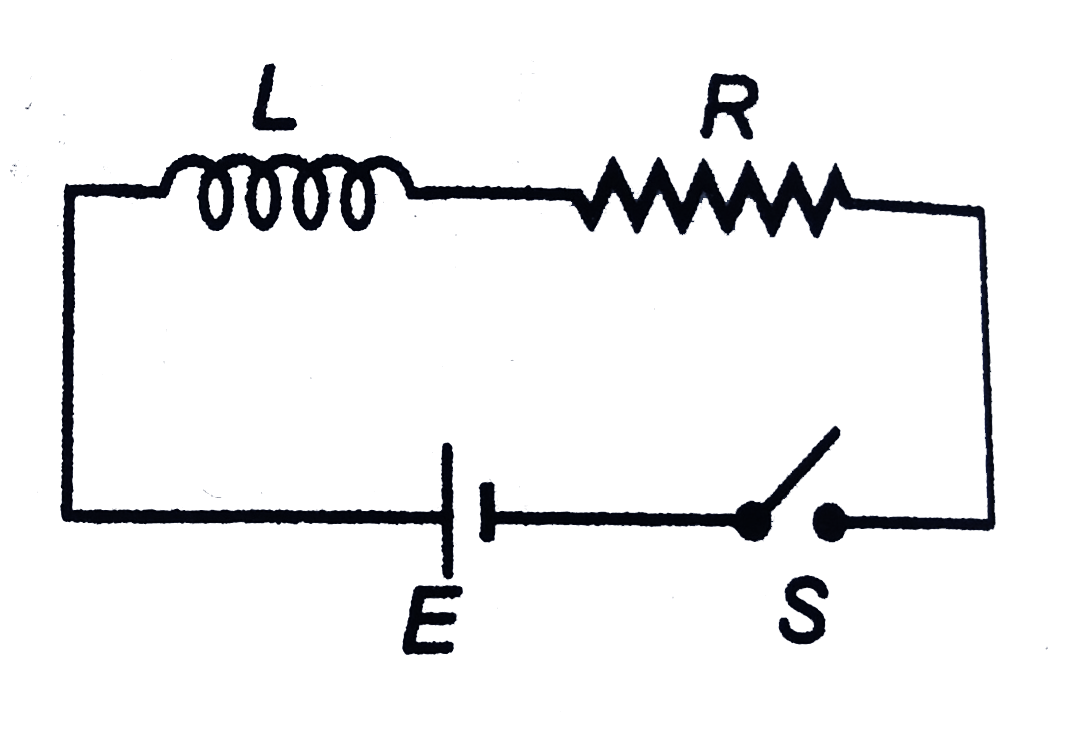
View SolutionIn the circuit shown in figure L=10H,R=5Ω,E=15V. The switch S is closed at t=0. At t=2s the current in the circuit is
View SolutionThe ratio of currents passing through resistance R_1 as shown in the figure, before and after switch S is closed, is (The potentials at A and B remain unchanged)
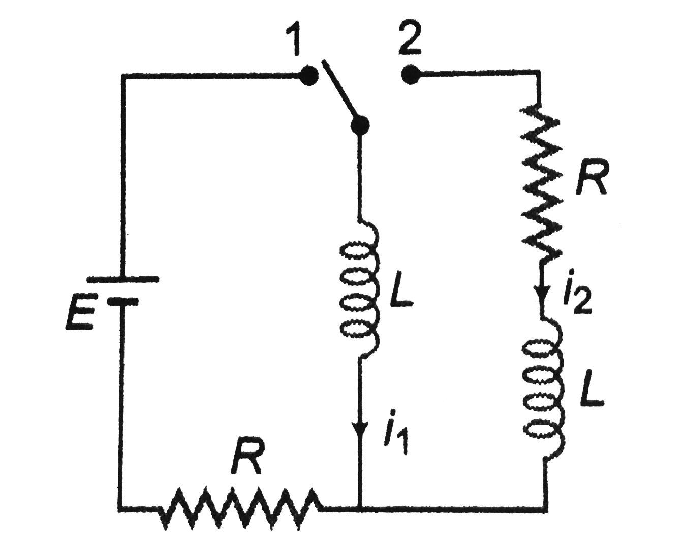
View SolutionIn figure, the switch is in the position 1 for long time, then the switch is shifted to position 2 at t=0. At this instant the value of i1 and i2 are
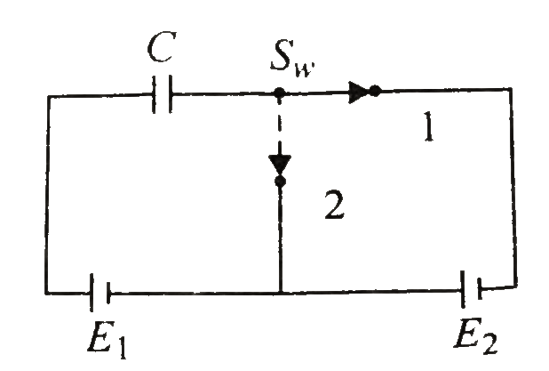
View SolutionIn the given circuit diagram figure, switch Sw is shifted from position 1 to position 2. Then
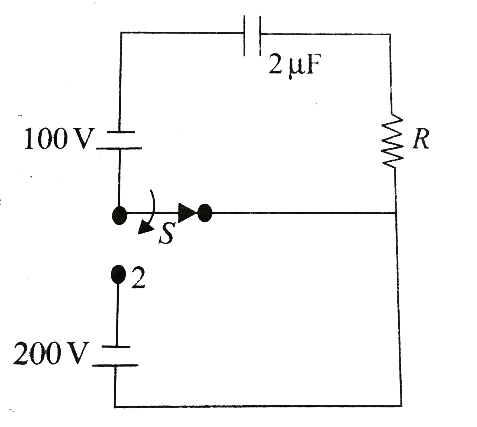
View SolutionIn the circuit shown in the figure, the switch S is in position 1 for a long time. Now the switch is thrown to position 2. Find the total heat developed in the circuit till the steady state is reached again.
View SolutionIn the circuit shown in figure switch S can be shift to position A or position B. Current though resistance is say i1 when switch is in position. A and when switch is in position B, then
View SolutionIn the given AC circuit, when switch S is at position 1, the source emf leads current by π6. Now, if the switch is at position 2, then

View Solution
