A potential of V=3000V is applied to a combination of four initially uncharged capacitors as shown in the figure. Capacitors A, B, C and D have capacitances CA=6.0μF,CB=5.2μF,CC=1.5μFandCD=3.8μF, respectiely. If the battery is disconnected, then potential difference across capacitor B is (approximately)

3000 V
zero
530 V
350 V
The correct Answer is:D
Step by step video & image solution for A potential of V = 3000 V is applied to a combination of four initially uncharged capacitors as shown in the figure. Capacitors A, B, C and D have capacitances C_(A)=6.0 muF,C_(B)=5.2 muF,C_(C)=1.5 muF and C_(D) = 3.8 muF, respectiely. If the battery is disconnected, then potential difference across capacitor B is (approximately) by Physics experts to help you in doubts & scoring excellent marks in Class 12 exams.
Updated on:21/07/2023Topper's Solved these Questions
- ELECTROSTATIC POTENTIAL AND CAPACITORSBOOK - DC PANDEY ENGLISHCHAPTER - ELECTROSTATIC POTENTIAL AND CAPACITORSEXERCISE - (B) Chapter exercises
17 Videos
- ELECTROSTATIC POTENTIAL AND CAPACITORSBOOK - DC PANDEY ENGLISHCHAPTER - ELECTROSTATIC POTENTIAL AND CAPACITORSEXERCISE - (C) Chapter exercises
50 Videos
- ELECTROSTATIC POTENTIAL AND CAPACITORSBOOK - DC PANDEY ENGLISHCHAPTER - ELECTROSTATIC POTENTIAL AND CAPACITORSEXERCISE - Check point 2.5
20 Videos
- ELECTROMAGNETIC WAVESBOOK - DC PANDEY ENGLISHCHAPTER - ELECTROMAGNETIC WAVESEXERCISE - Sec C
22 Videos
- ELECTROSTATICSBOOK - DC PANDEY ENGLISHCHAPTER - ELECTROSTATICSEXERCISE - Medical entrances gallery
37 Videos
Similar Questions
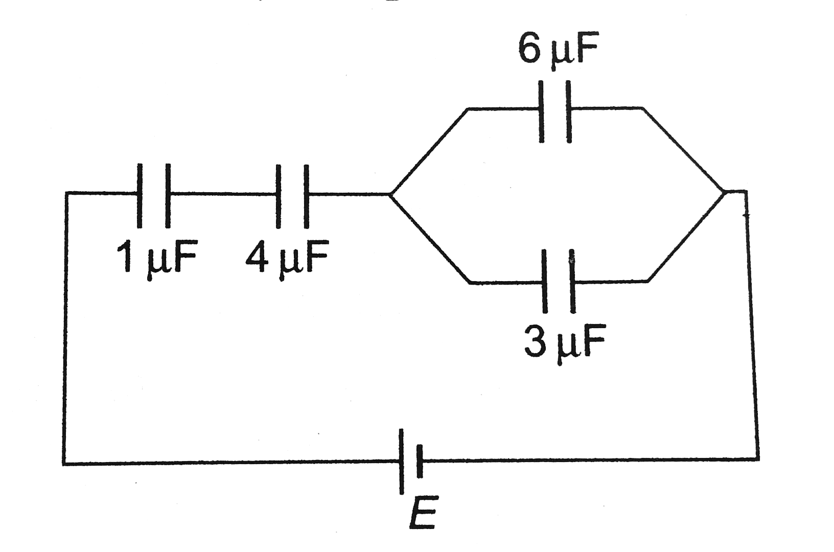
given that potential differene across 1μF capacitor is 10V. Then,
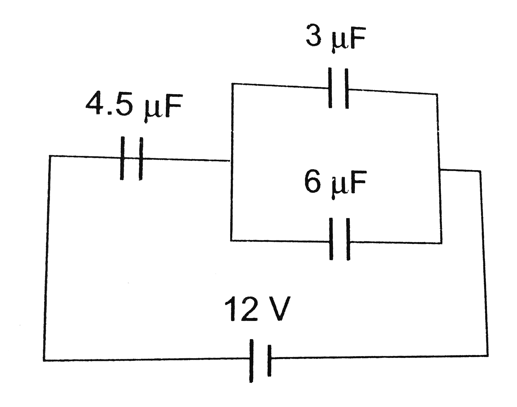
View SolutionIn the adjoning figure, the potential difference across the 4.5μF capacitor is

View SolutionWhat is the potential difference across 2μF capacitor in the circuit shown?
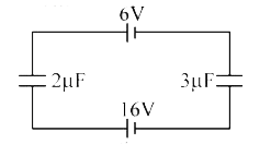
View SolutionThe potential drop across 7μF capacitor is 6V. Then

View SolutionIn the circuit shown in the figure, the potential difference across the 4.5μF capacitor is
View SolutionIn, given C1=3μF,C2=5μF,C3=9μF, and C4=13μF. What is the potential differnce between points A and B?
 .
.
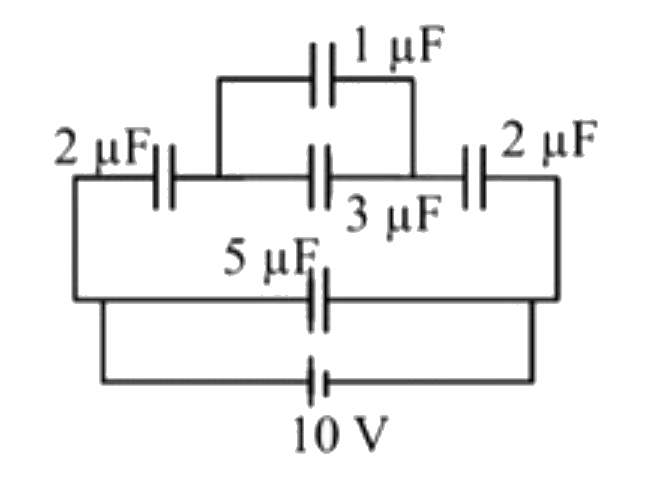
View SolutionThe ratio of potential differences between 1μFand5μF capacitors is
View Solution
(i) Find the equivalent capacitance of the combination shown in the figure (a), when C1=2.0μF,C2=4.0μFandC3=3.0μF
(ii) The input terminals A and B in Fig. (a) are connected to a battery of 12 V. Find the potential and the charge of each capacitor.
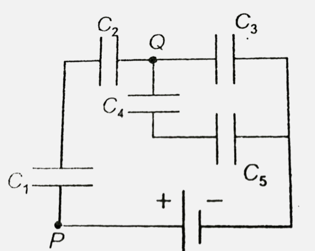
View SolutionIn the circuit shown C1=15μF,C2==30μF,C3=30μF,C4=30μF and C5=60μF. At steady state, the potential difference between points P and Q is 50 V. Calculate the potential difference across capacitor with capacitance C5
View SolutionThe equivalent capacity between A and B in the given circuit is (C1=4μF,C2=12μF,C3=8μF,C4=4μF,C5=8μF)

View Solution
