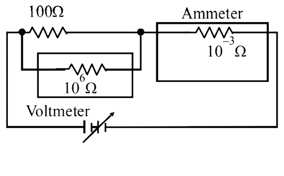
Draw the circuit diagram to verify Ohm's Law with the help of a main resistance of 100Ω and tow galvanometer of resistance 106Ωand10−3Ω and a source of varying emf.
Show the correct positions of volmeter and ammeter.
The correct Answer is:A
For the experiment verification of Ohm's law, ammeter and
voltmeter should be connected as shown in figure.
A voltmeter is a high resistance galvanometer (106Ω) which
is connected in paralllel with the main resistance of 100Ω
An ammeter is a low resistance galvanometer (10^(-3)Omega) which
is connected in parallel with the main resistance.
 .
.
Topper's Solved these Questions
Similar Questions
Draw the circuit for experimental verification of Ohm's law using a source of variable DC voltage, a main resistance of 100Ω, two galvanometers and two resistances of value 106Ω and 10−3Ω respectively. Clearly show the positions of the voltmeter and the ammeter.
View SolutionDraw the circuit for experimental verfication of Ohm's law using a source of variable DC voltage, a main resistance of 100(Ω), two galvanometers and two resistances of values 106Ω and 10−3 respectively. Clearly show the positions of the voltmeter and the ammeter.
View Solution
Knowledge Check
A galvanometer of resistance 25Ω measures 10−3A . shunt required to increase range up tow 2 A is
A12.5mΩB0.125mΩC0.125ΩD1.25mΩAn experiment is performed to calculate the value of an unknown resistance R of range K Ω by using a battery of variable potential difference, a voltmeter of resistance 106Ω and an ammeter of resistance 10−3Ω. Choose the circuit diagram which indicates correctly the position of ammeter and voltmeter so that percentage error in calculation of R is minimum
A B
B C
C Dnone of the above
A galvanometer of resistance 90 Ω is shunted by a resistance of 10 Ω. What fraction of main current passes through the shunt ?
A1/10B9/100C1/100D9/10
How will you join the resistors of resistances 3Ω,6Ω and 8Ω to get an equivalent resistance of 10Ω?
View SolutionJudge the equivalent resistance when the following are connected in parallel:
1Ωand103Ωand106Ω.
View SolutionWhat is the value of shunt resistance required to convert a galvanometer of resistance 100Ω into an ammeter of range 1A ? (Given : Full scale deflection of the galvanometer is 5 mA.)
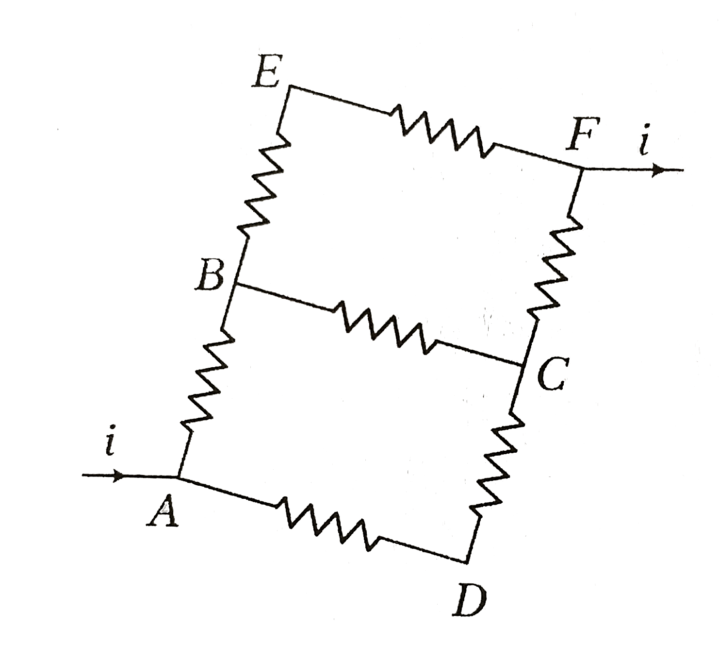
View SolutionIn the given circuit diagram if each resistance is of 10Ω, then the current in arm AD will be

View SolutionTo convert a 400 m V range galvanometer of resistance 20Ω into a ammeter of 100 m A ranges , the required shunt resistance to be connected is
View Solution
