IF VAandVB are the input voltages (either 5 V or 0 V) and Vo is the output voltage then the two gates represented in the following circuits (A) and (B) are :
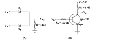
AND and OR Gate
NAND and NOR Gate
AND and NOT Gate
OR and NOT Gate
Step by step video & image solution for IF V_(A)andV_(B) are the input voltages (either 5 V or 0 V) and V_(o) is the output voltage then the two gates represented in the following circuits (A) and (B) are : by Physics experts to help you in doubts & scoring excellent marks in Class 12 exams.
Topper's Solved these Questions
- BOOK - JEE MAINS PREVIOUS YEARCHAPTER - JEE MAINS 2021EXERCISE - Physics Section B20videos
JEE MAINS 2021
- BOOK - JEE MAINS PREVIOUS YEARCHAPTER - JEE MAINS 2021EXERCISE - Physics (Section A)81videos
JEE MAINS 2021
- BOOK - JEE MAINS PREVIOUS YEARCHAPTER - JEE MAINS 2021EXERCISE - PHYSICS30videos
JEE MAINS 2021
- BOOK - JEE MAINS PREVIOUS YEARCHAPTER - JEE MAINS 2020EXERCISE - PHYSICS246videos
JEE MAINS 2020
- BOOK - JEE MAINS PREVIOUS YEARCHAPTER - JEE MAINS 2022EXERCISE - PHYSICS (SECTION -B)10videos
JEE MAINS 2022
Similar Questions
Knowledge Check
- Question 1 - Select One
In a step up transformer, the input voltage is 300 V and the output voltage is 15 KV. Then the ratio of the number of turns in the primary to that in the secondary is
A1:20B1:30C1:40D1:50 - Question 2 - Select One
In a step - down transformer the input voltage is 22kV and the output voltage is 550V The ratio of the number of turns in the secondary to that in the primary is .
A1:20B20:1C1:40D40:1 - Question 3 - Select One
Alternating voltage (V) is represented by the equation
whrere Vm is the peak voltageAVt=VmeωtBVt=VmsinωtCV(t)=VmcotωtDV(t)=Vmtantωt
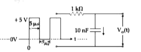
For the given input voltage wavelength Vin(t) , the output voltage waveform (V0)(t) , across the capacitor is correctly depicted by :
 View Solution
In an ideal step down transformer, the input voltage is 400V and the output voltage is 20 V. The output voltage is used to operate a device, having an impendance of 100 ohms. What is the current in the primary circuit?
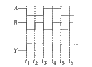
View SolutionThe figure shows the voltage waveforms across two inputs A and B and the output Y of a logic circuit. The logic circuit gate is
 View Solution
In a circuit a diode was used and the output voltage across the diode was always 50 volts, even if the input voltage fluctuated between 110 V to 90 V. The diode used in the circuit was
View SolutionIn an LCR series ac circuit the voltage across L,C and R are V1,V2 and V3 respectively The voltage of the source is .
View Solution


