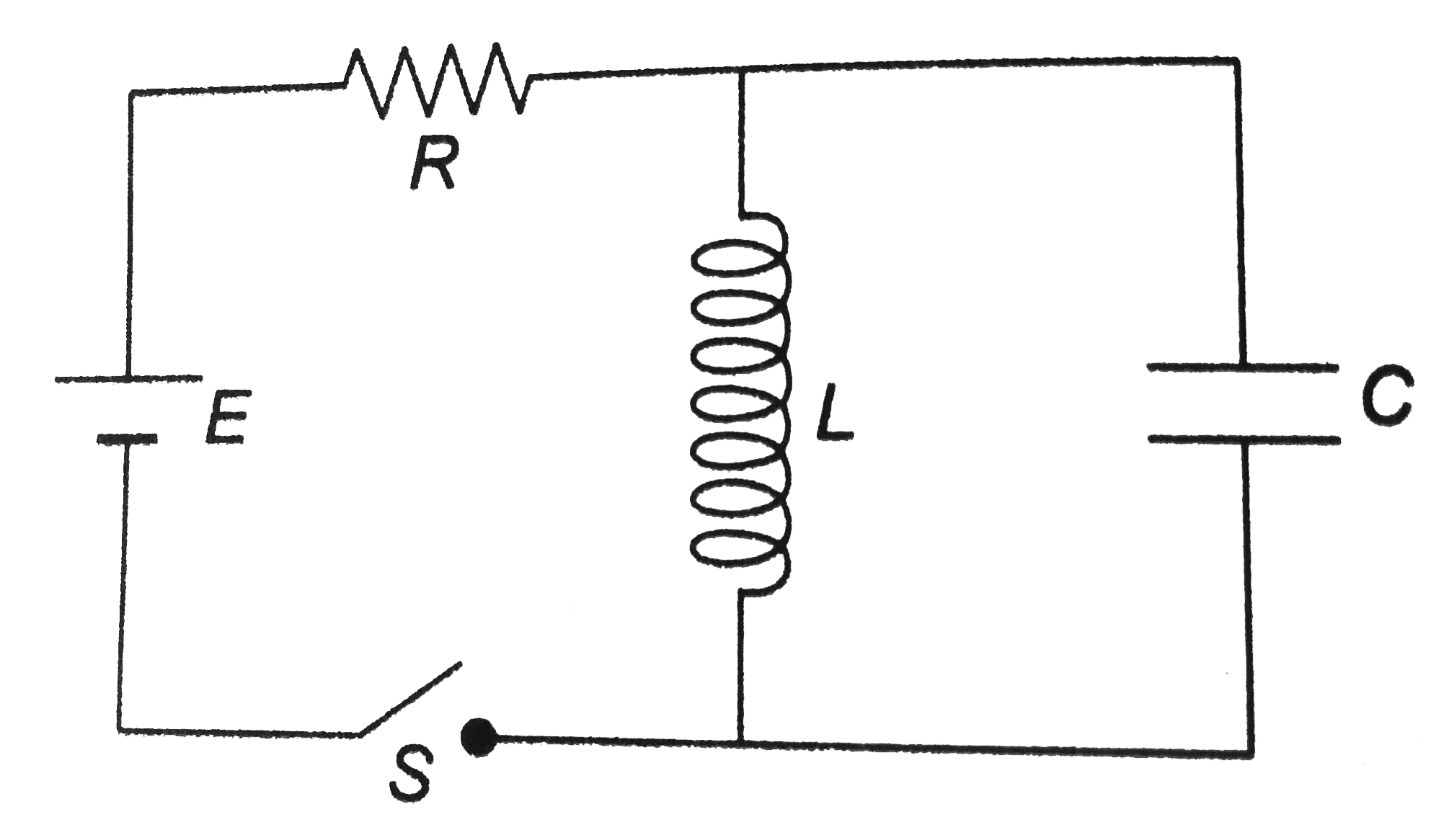
In the circuit shown in the figure, E=50.0V,R=250Ω and C=0.500μF. The switch S is closed for a long time, and no voltage is measured across the capacitor. After the switch is opened, the voltage across the capacitor reaches a maximum value of 150V. What is the inductance L?
The correct Answer is:B
In steady state when switch was closed,
i0=E/R=(1/5)A=0.2A
After switch is opened it becomes L−C circuit in which peak value current is 0.2A.
∴12Li20=12CV20
or L=V20i20.C
=(150)2(0.2)2×0.5×10−6
=0.28H
Topper's Solved these Questions
- ELECTROMAGNETIC INDUCTIONBOOK - DC PANDEYCHAPTER - ELECTROMAGNETIC INDUCTIONEXERCISE - Check point
60 Videos
- ELECTROMAGNETIC INDUCTIONBOOK - DC PANDEYCHAPTER - ELECTROMAGNETIC INDUCTIONEXERCISE - Taking it together
119 Videos
- ELECTROMAGNETIC INDUCTIONBOOK - DC PANDEYCHAPTER - ELECTROMAGNETIC INDUCTIONEXERCISE - SUBJECTIVE TYPE
1 Videos
- CURRENT ELECTRICITYBOOK - DC PANDEYCHAPTER - CURRENT ELECTRICITYEXERCISE - Medical entrances gallery
97 Videos
- ELECTROMAGNETIC WAVESBOOK - DC PANDEYCHAPTER - ELECTROMAGNETIC WAVESEXERCISE - Sec C
22 Videos
Similar Questions
Knowledge Check
In the circuit of figure, the battery emf is g the resitance is R and the capacitance is C. The switch S is closed for a long time interval, and zero potential difference is measured across the capacitor

After the switch is opened. the potential difference across the capacitor reaches a maximum value of ΔV. What is the value of the inductance?AC(ΔV)22ε2BC(ΔV)2ε2C2C(ΔV)2ε2DC(ΔV)24ε2In the circuit shown in fig, switch S was closed for long time. At time t-0, teh switch is opened again. The maximum potential difference across teh plates of the capacitor after the switch is opened is
 A10VB100VC20VD200V
In the circuit in Fig. switch S1 was closed for a long time . At time t=0 the switch is opened.
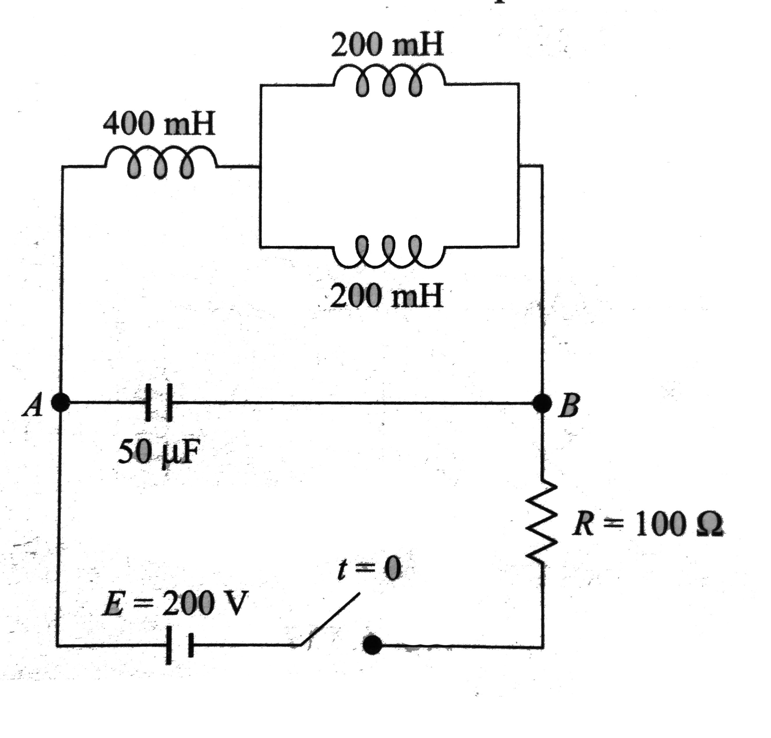
Find the maximum potentail difference across the plates of the capacitor after the switch is opened.A100VB200VC300VD400V
In the circuit shown in figure, E=120V,R1=30.0Ω,R2=50.0Ω and L=0.200H. Switch S is closed at t=0. Just after the switch is closed.
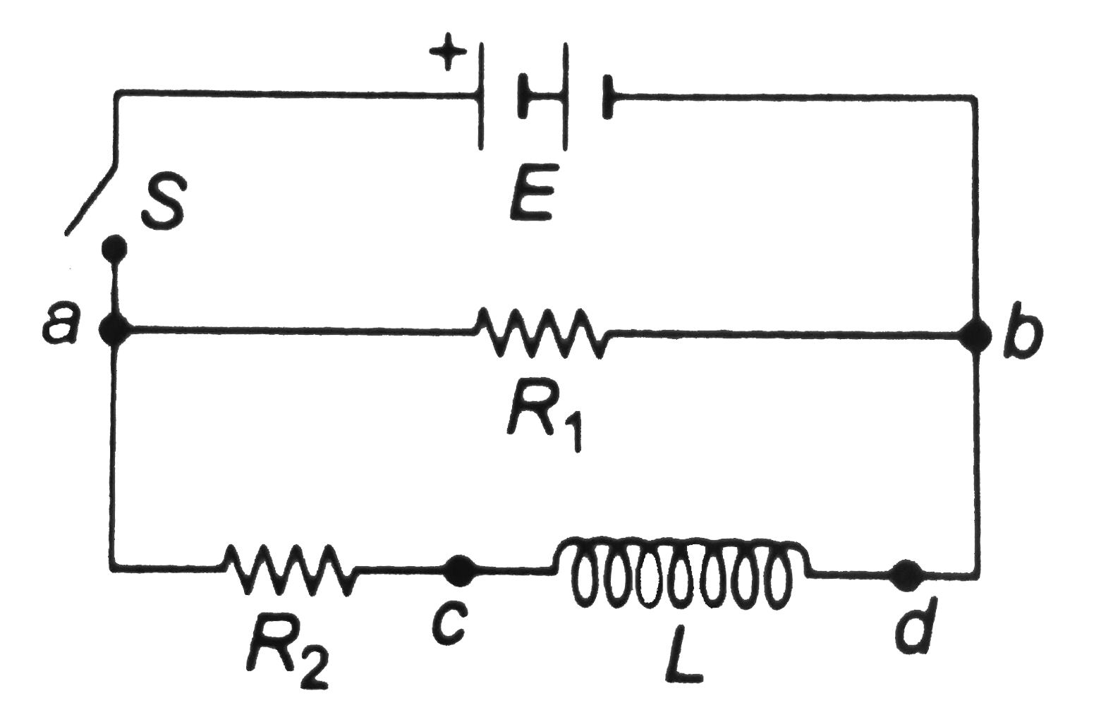
(a) What is the potential difference Vab across the inductor R1?
(b) Which point, a or b, is at higher potential?
(c) What is the potential difference Vcd across the inductor L?
(d) Which point, c or d, is at a higher potential? The switch is left closed for a long time and then is opened. Just after the switch is opened
(e) What is the potential difference Vab across the resistor R1?
(f) Which point a or b, is at a higher potential?
(g) What is the potential difference Vcd across the inductor L?
(h) Which point, c or d, is at a higher potential?
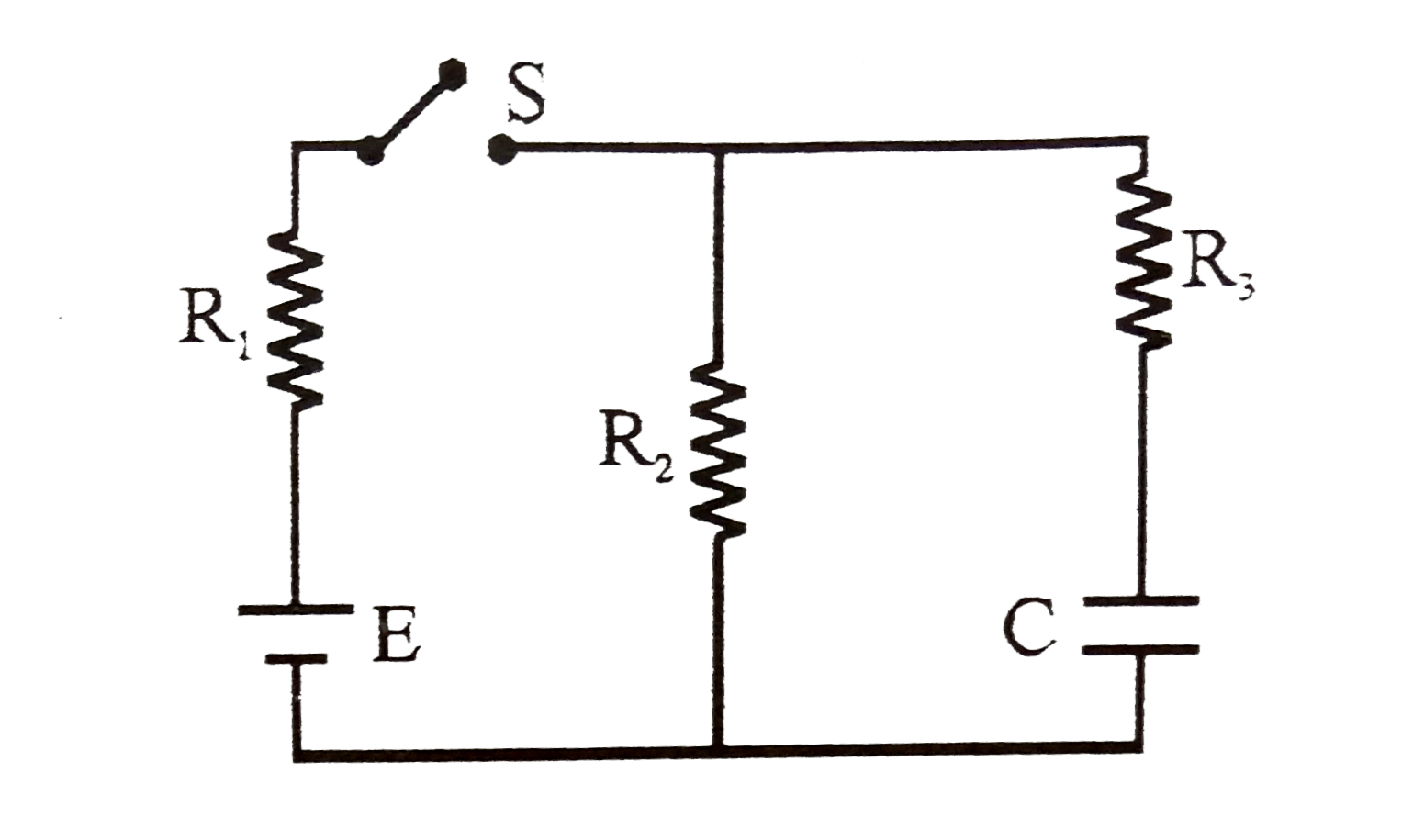
View SolutionIn the circuit shown in figure R1=R1=6R3=300MΩ,C=0.01μF and E−10V. The switch is closed at t=0, find
(a) Charge on capacitor as a function of time
(b) enegry of the capacitor at t=20s
View SolutionFind how the voltage across the capacitor C varies with time t after closing of the switch Sw at the moment t=0.
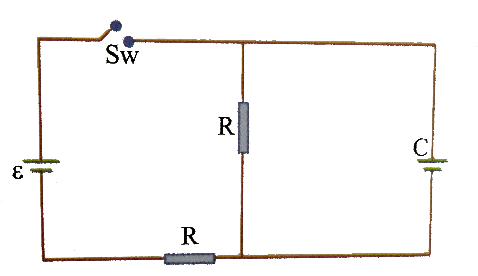 .
.
View SolutionIn the circuit in Fig. switch S1 was closed for a long time . At time t=0 the switch is opened.
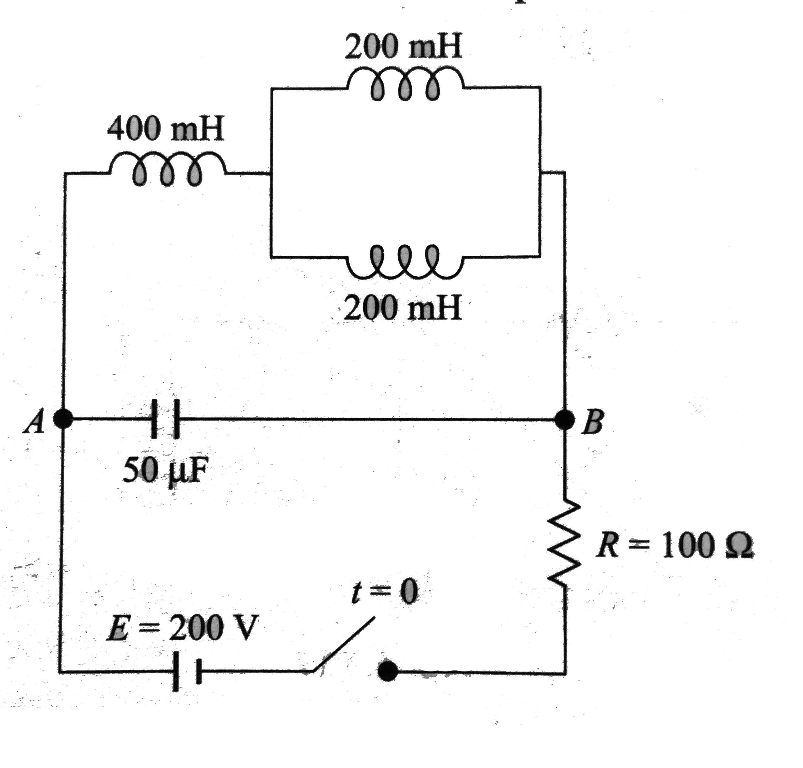
Find the angular frequency of oscillation of the charge on the capacitor.
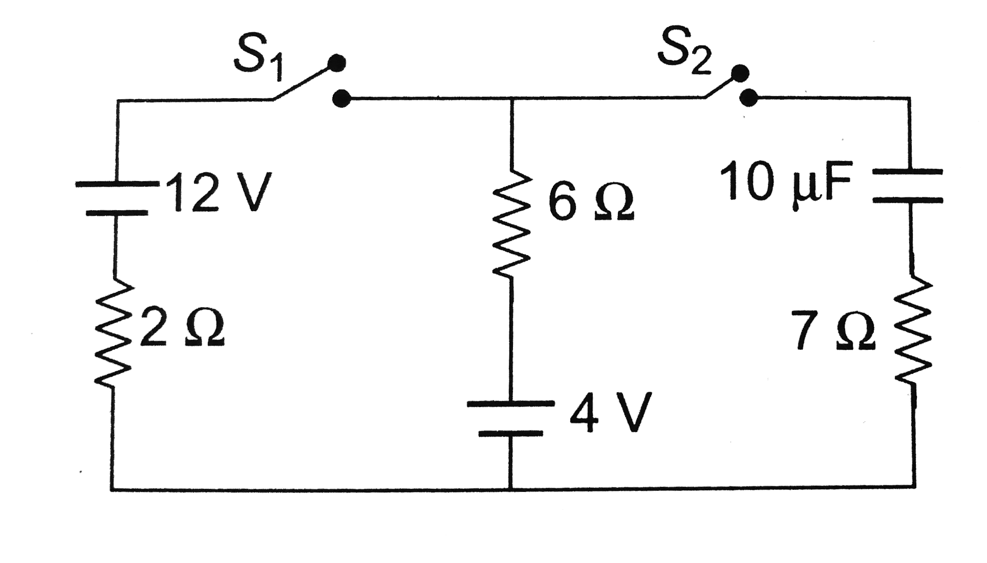
View SolutionIn the circuit shown in the figure, if switches S1 and S2 have been closed for a long time, then charge on the capacitor.
View Solution

