It is required to design a (two -input) logic gate, using an appropriate number, of :
(a) NAND gates that gives a 'low' output only when both the inputs are 'low'.
(b) NOR gates that gives a 'high' output only when both the inputs are 'high'.
Draw the logic circuits for these two cases and write the truth table, corresponding to each of the two designs.
To solve the problem, we need to design two types of logic gates using NAND and NOR gates, and create corresponding truth tables for each design.
Part (a): Designing a NAND Gate Circuit
Objective: Create a logic gate using NAND gates that gives a 'low' output only when both inputs are 'low'.
Step 1: Identify the required output condition.
- The output should be 'low' (0) only when both inputs (A and B) are 'low' (0, 0). In all other cases, the output should be 'high' (1).
Step 2: Use NAND gates to achieve the desired output.
- The NAND gate gives a 'low' output only when both inputs are 'high'. Therefore, we need to manipulate the inputs to achieve the desired output.
Step 3: Connect the inputs to the NAND gates.
- Use two NAND gates:
1. Connect inputs A and B to the first NAND gate. The output will be \( \overline{A \cdot B} \).
2. Connect the output of the first NAND gate to both inputs of the second NAND gate. The output of the second NAND gate will be \( \overline{\overline{A \cdot B}} = A \cdot B \).
Step 4: Draw the logic circuit.
- The circuit will look like this:
A−−−−|NAND⊢−−|NAND⊢−−Y(Output)|||B−−−−|||
Step 5: Write the truth table.
|A|B|Y(Output)|⊢−⊢−⊢−−−−−−−−−−−||0|0|0||0|1|1||1|0|1||1|1|1∣
Part (b): Designing a NOR Gate Circuit
Objective: Create a logic gate using NOR gates that gives a 'high' output only when both inputs are 'high'.
Step 1: Identify the required output condition.
- The output should be 'high' (1) only when both inputs (A and B) are 'high' (1, 1). In all other cases, the output should be 'low' (0).
Step 2: Use NOR gates to achieve the desired output.
- The NOR gate gives a 'high' output only when both inputs are 'low'. Therefore, we need to manipulate the inputs to achieve the desired output.
Step 3: Connect the inputs to the NOR gates.
- Use two NOR gates:
1. Connect inputs A and B to the first NOR gate. The output will be \( \overline{A + B} \).
2. Connect the output of the first NOR gate to both inputs of the second NOR gate. The output of the second NOR gate will be \( \overline{\overline{A + B}} = A + B \).
Step 4: Draw the logic circuit.
- The circuit will look like this:
A−−−−|NOR⊢−−|NOR⊢−−Y(Output)|||B−−−−|||
Step 5: Write the truth table.
|A|B|Y(Output)|⊢−⊢−⊢−−−−−−−−−−−||0|0|0||0|1|0||1|0|0||1|1|1∣
Summary of Solutions
1. NAND Gate Circuit:
- Logic Circuit: Two NAND gates connected as described.
- Truth Table:
|A|B|Y|⊢−⊢−⊢−||0|0|0||0|1|1||1|0|1||1|1|1∣
2. NOR Gate Circuit:
- Logic Circuit: Two NOR gates connected as described.
- Truth Table:
|A|B|Y|⊢−⊢−⊢−||0|0|0||0|1|0||1|0|0||1|1|1∣
- The output should be 'low' (0) only when both inputs (A and B) are 'low' (0, 0). In all other cases, the output should be 'high' (1).
- The NAND gate gives a 'low' output only when both inputs are 'high'. Therefore, we need to manipulate the inputs to achieve the desired output.
- Use two NAND gates:
1. Connect inputs A and B to the first NAND gate. The output will be \( \overline{A \cdot B} \).
2. Connect the output of the first NAND gate to both inputs of the second NAND gate. The output of the second NAND gate will be \( \overline{\overline{A \cdot B}} = A \cdot B \).
- The circuit will look like this:
A−−−−|NAND⊢−−|NAND⊢−−Y(Output)|||B−−−−|||
|A|B|Y(Output)|⊢−⊢−⊢−−−−−−−−−−−||0|0|0||0|1|1||1|0|1||1|1|1∣
- The output should be 'high' (1) only when both inputs (A and B) are 'high' (1, 1). In all other cases, the output should be 'low' (0).
- The NOR gate gives a 'high' output only when both inputs are 'low'. Therefore, we need to manipulate the inputs to achieve the desired output.
- Use two NOR gates:
1. Connect inputs A and B to the first NOR gate. The output will be \( \overline{A + B} \).
2. Connect the output of the first NOR gate to both inputs of the second NOR gate. The output of the second NOR gate will be \( \overline{\overline{A + B}} = A + B \).
- The circuit will look like this:
A−−−−|NOR⊢−−|NOR⊢−−Y(Output)|||B−−−−|||
|A|B|Y(Output)|⊢−⊢−⊢−−−−−−−−−−−||0|0|0||0|1|0||1|0|0||1|1|1∣
- Logic Circuit: Two NAND gates connected as described.
- Truth Table:
|A|B|Y|⊢−⊢−⊢−||0|0|0||0|1|1||1|0|1||1|1|1∣
- Logic Circuit: Two NOR gates connected as described.
- Truth Table:
|A|B|Y|⊢−⊢−⊢−||0|0|0||0|1|0||1|0|0||1|1|1∣
Topper's Solved these Questions
- XII BOARDSBook:XII BOARD PREVIOUS YEAR PAPER ENGLISHChapter:XII BOARDSExercise:C.B.S.E.CLASS-XII PHYSICS (THEORY) [SET-I] (SECTION-A)
Explore 5 Videos
- XII BOARDSBook:XII BOARD PREVIOUS YEAR PAPER ENGLISHChapter:XII BOARDSExercise:SECTIONS-B
Explore 4 Videos
- XII BOARDSBook:XII BOARD PREVIOUS YEAR PAPER ENGLISHChapter:XII BOARDSExercise:SECTION-C
Explore 50 Videos
- SAMPLE PAPER 2019Book:XII BOARD PREVIOUS YEAR PAPER ENGLISHChapter:SAMPLE PAPER 2019Exercise:SECTION D
Explore 6 Videos
Similar Questions
An XOR gate produces an output only when its two inputs are :-
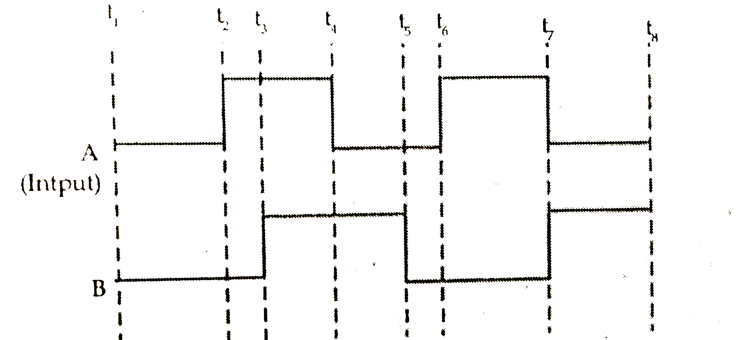
View SolutionThe figure shows the input weveforms A and B for 'AND' gate Draw the output waveform and write the truth table for this logic gate
 .
.
View SolutionIdentify the logic gate whose output equals 1 when both of its inputs are 0 each.
View SolutionWhen the inputs of a two input logic gate are 0 and 0, the output is 1. When the inputs are 1 and 0, the output is zero. The type of logic gate is
View SolutionThe output of gate is low when at least one of its input is high. This is true for :-
View SolutionThe output of a two input NOR gate is in state 1 when :-
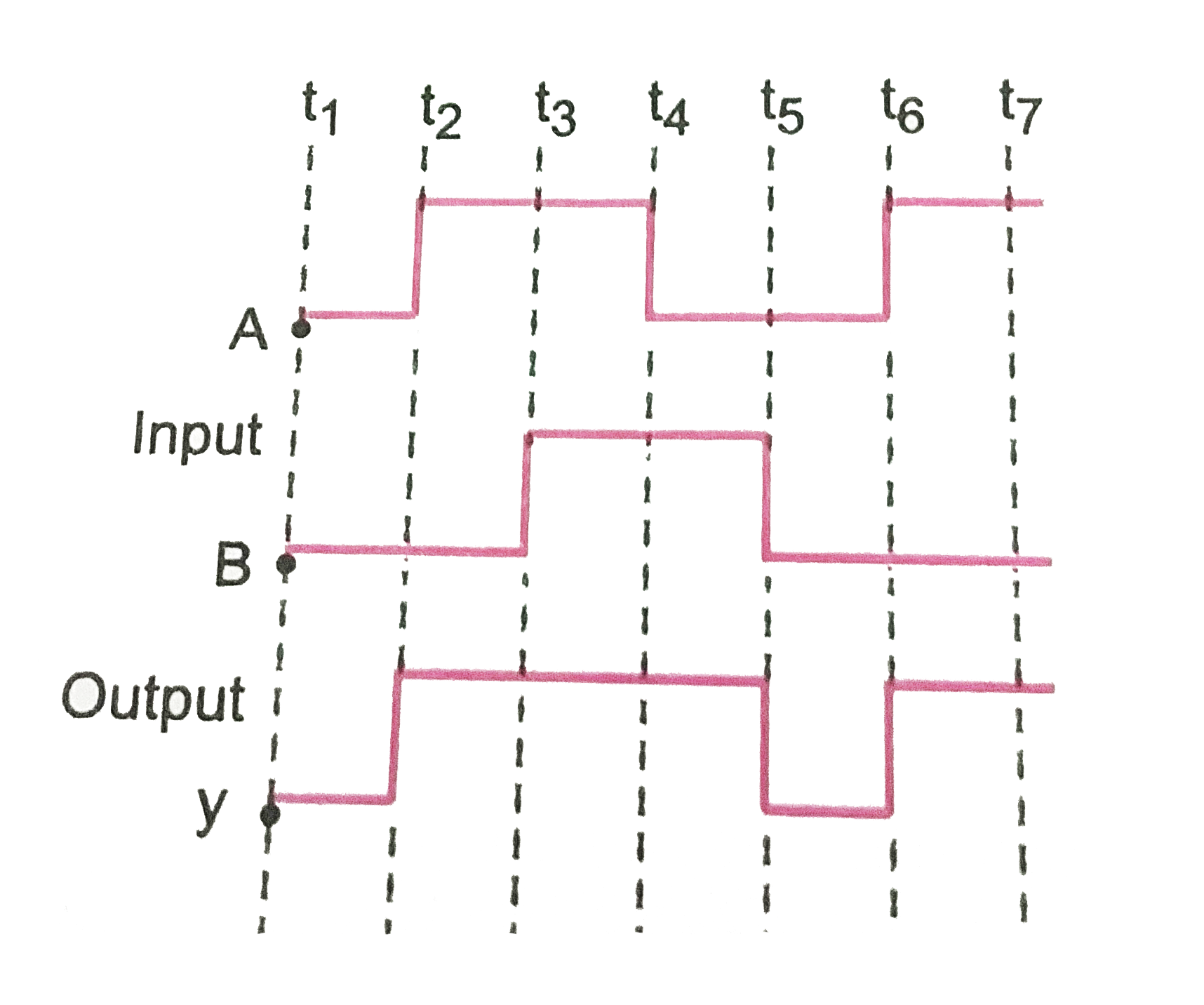
View SolutionUsing the wave forms of the input A and B, draw the output waveform of the given logic circuit . Identify the logic gate obtained . Write also the truth table.

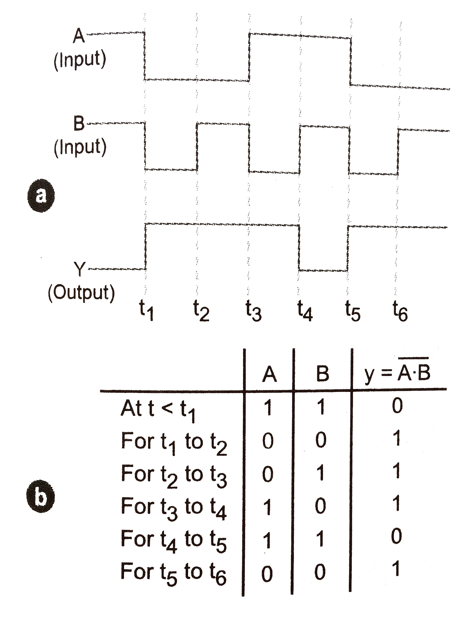
View SolutionThe following Fig. shows the input waveforms (A,B) and the output waveform (y) of a gate. Identify the gate and write its truth table.

View SolutionThe Fig shown input waveforms A and B to a logic gate. Draw the output waveform for an OR gate. Write the truth table for this logic gate and draw its logic symbol.

View SolutionThe output of the given logic gate is 1 when inputs A,B and C are such that :-
_E01_413_Q01.png)
View Solution
