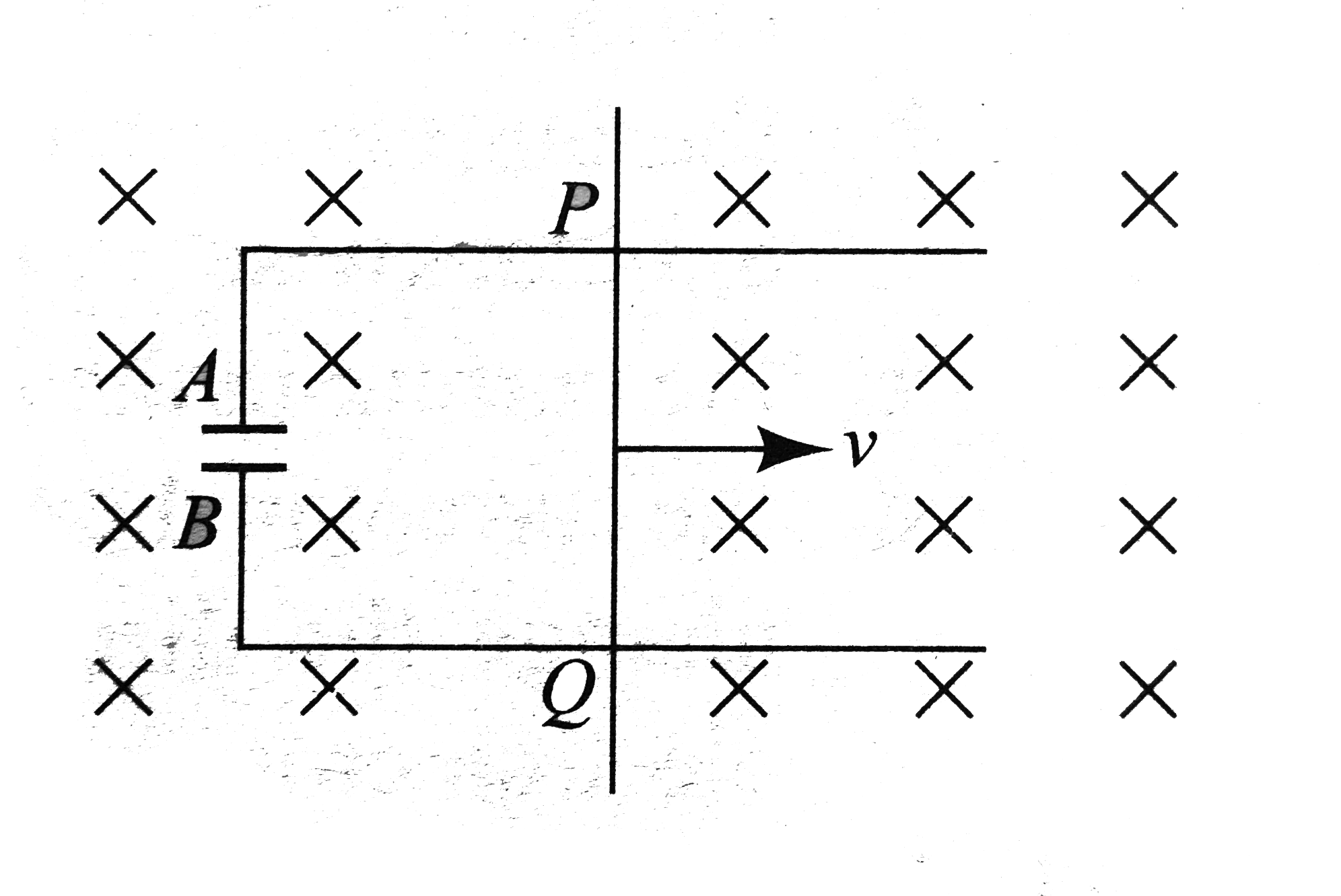
The conducting rod ab shown in figure makes contact with metal rails ca and db. The apparatus is in a uniform magnetic field 0.800T, perpendicular to the plane of the figure.
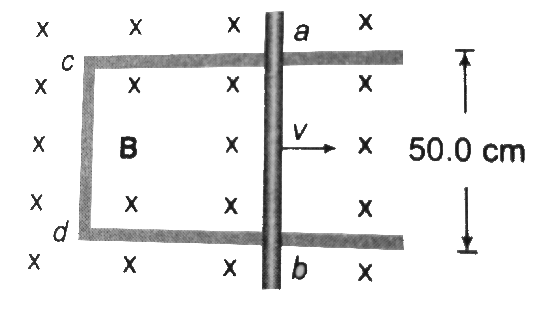
(a) Find the magnitude of the emf induced in the rod when it is moving toward the right with a speed 7.50m/s.
(b) In what direction does the current flow in the rod?
(c) If the resistance of the circuit abdc is 1.50Ω (assumed to be constant), find the force (magnitude and direction) required to keep the rod moving to the right with a constant speed of 7.50m/s. You can ignore friction.
(d) Compare the rate at which mechanical work is done by the force (Fu) with the rate at which thermal energy is developed in the circuit (I2R).
The correct Answer is:A, B
a. e=Bvl=0.8×7.5×0.5=3V
b. Current will flow in anti clockwise direction, as magnetic field in ⊗ direction passing through the closed loop is increasing. Therefore, induced current will produce magnetic field in ⊙ direction.
c. F=Fm=ilB=eRlB=(BvlR)Bl=B2l2Rv
=(0.8)2(0.5)21.5×7.5=0.8N
d. Fv=0.8×7.5=6w
i2R=(BvlR)2R=B2l2R.v2
=(0.8)2(0.5)21.5×(7.5)2=6W
So we can see that both rates are equal.
Topper's Solved these Questions
- ELECTROMAGNETIC INDUCTIONBOOK - DC PANDEYCHAPTER - ELECTROMAGNETIC INDUCTIONEXERCISE - Check point
60 Videos
- ELECTROMAGNETIC INDUCTIONBOOK - DC PANDEYCHAPTER - ELECTROMAGNETIC INDUCTIONEXERCISE - Taking it together
119 Videos
- ELECTROMAGNETIC INDUCTIONBOOK - DC PANDEYCHAPTER - ELECTROMAGNETIC INDUCTIONEXERCISE - SUBJECTIVE TYPE
1 Videos
- CURRENT ELECTRICITYBOOK - DC PANDEYCHAPTER - CURRENT ELECTRICITYEXERCISE - Medical entrances gallery
97 Videos
- ELECTROMAGNETIC WAVESBOOK - DC PANDEYCHAPTER - ELECTROMAGNETIC WAVESEXERCISE - Sec C
22 Videos
Similar Questions
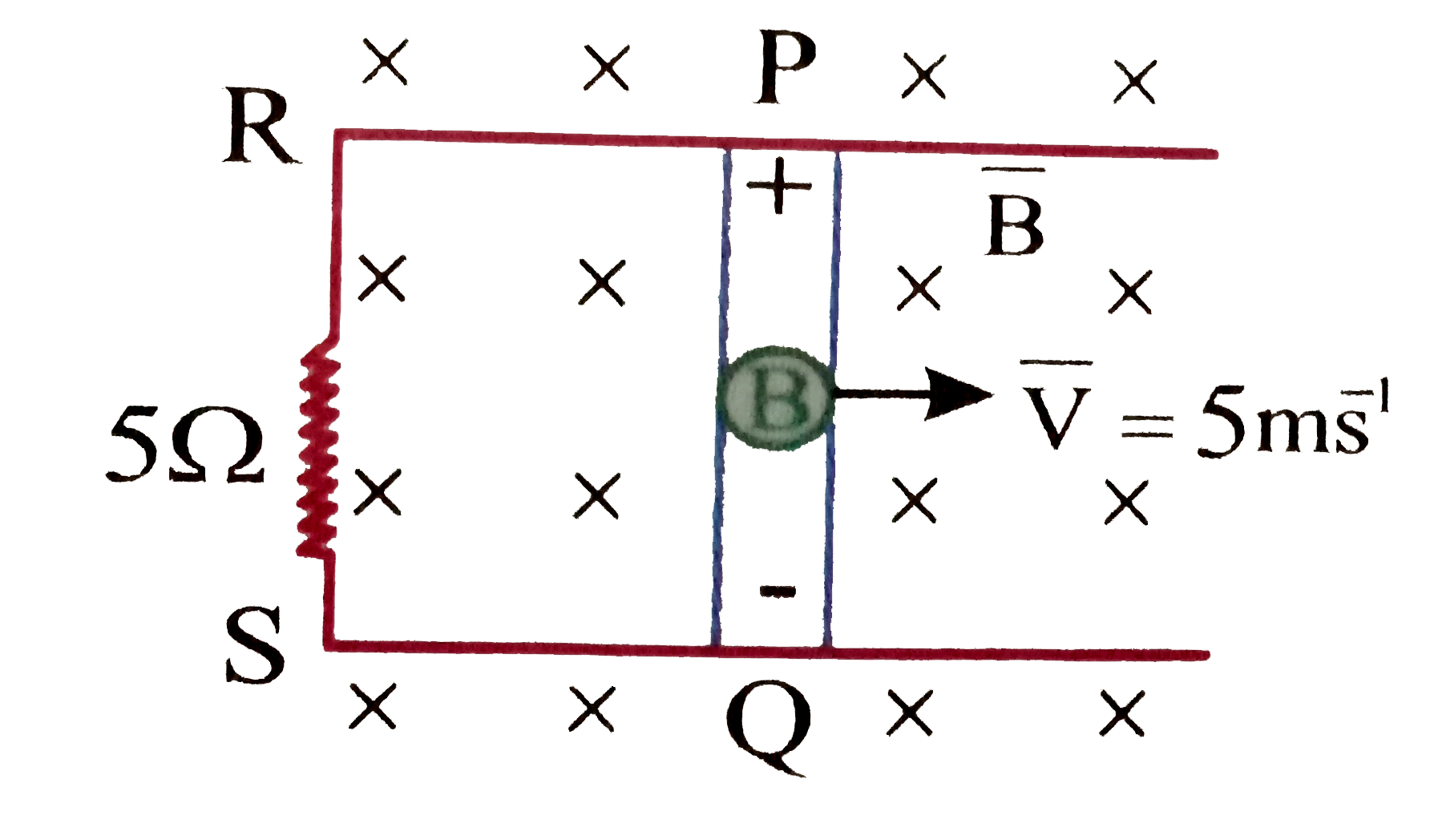
Figure shows a conducting rod PQ in contact with metal rails RP and SQ, which are 0.25m apart in a uniform magnetic field of flux density 0.4T acting perpendicular to the plane of the paper. Ends R and S are connected through a 5Ω resistance. What is the emf when the rod moves to the right with a velocity of 5ms−1 ? What is the magnitude and direction of the current through the 5Ω resistance? If the rod PQ moves to the left with the same speed, what will be the new current and its direction?
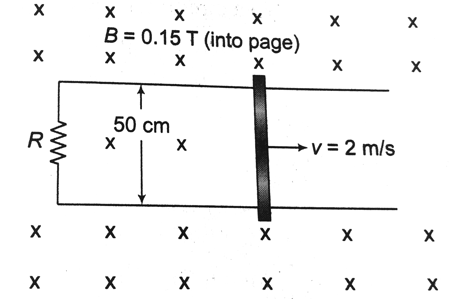
View SolutionAs shown in figure, a metal rod completes the circuit. The circuit area is perpendicular to a magnetic field with B=0.15T. If the resistance of the total circuit is 3Ω, how large a force is needed to move the rod as indicated with a constant speed of 2 m/s?
View Solution
Knowledge Check
A conducting rod AB moves parallel to x-axis in a uniform magnetic field pointing perpendicular and into the plane of paper. The end A of the rod
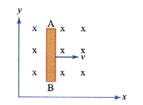 Agets positively chargedBgets negatively chargedCremains neutralDgets positively charged first and then negatively charged
A wire is bent in the form of a V shape and placed in a horizontal plane. There exists a uniform magnetic field B perpendicular to the plane of the wire. A uniform conducting rod starts sliding over the V shaped wire with a constant speed v as shown in the figure. If the wire no resistance, the current in rod wil
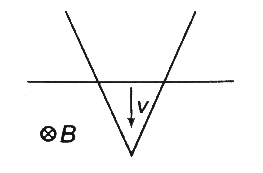 Aincrease with timeBdecrease with timeCremain constantDalways be zero
In the figure shown as uniform magnetic field |B|=0.5T is perpendicular to the plane of circuit. The sliding rod of length l=0.25m moves uniformly with constant speed v=4ms−1. If the resistance of the sllides is 2Ω, then the current flowing through the sliding rod is
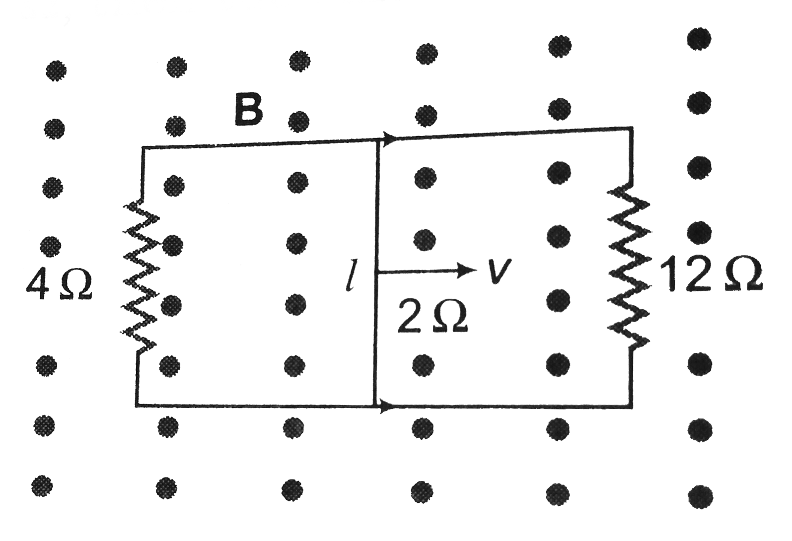 A0.1AB0.17AC0.08D0.03A
A thin rod of copper is being moved in a uniform magnetic field such that it is cutting the magnetic field lines. An emf is induced between the ends of the rod.
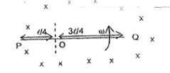
View SolutionA conducting rod of length l is rotating with constant angular velocity ω about point O in a uniform magnetic field B as shown in the figure . What is the emf induced between ends P and Q ?
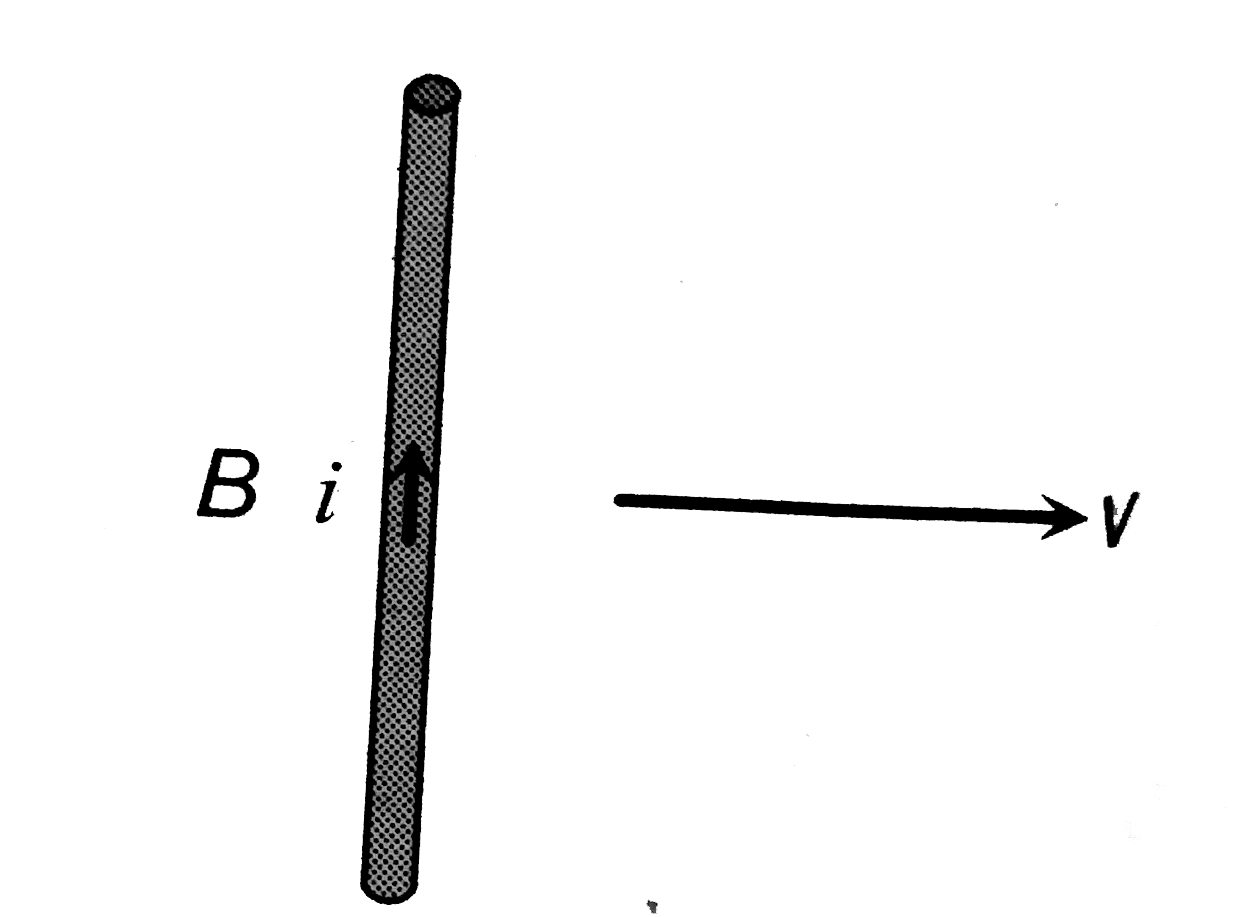
View SolutionA conducting wire is moving towards right in a magnetic field B. The direction of induced current in the wire is shown in the figure. The direction of magnetic field will be
View SolutionA conducting rod PQ of length L=1.0m is moving with a uniform speed v=2.0ms−1 in a uniform magnetic field B=4.0T directed into the plane of the paper.
A capacitor of capacity C=10μF is connected as shown in , then
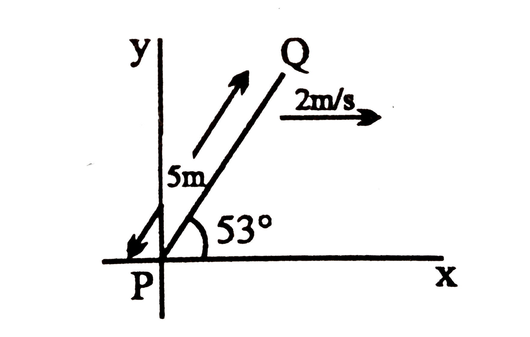
View SolutionA conducting rod PQ of length 5m oriented as shown in figure is moving with velocity (2m/s)ˆi without any rotation in a uniform magnetic field (3ˆj+4ˆk) Tesla. Emf induced in the rod is
View Solution
