Complete Solutions to Diode In Circuits of chapter SEMICONDUCTOR ELECTRONICS of Class 12 book with complete answers and questions
| Class 12 | PHYSICS |
| Chapter | SEMICONDUCTOR ELECTRONICS |
| A2Z | Diode In Circuits |
| Number Of Questions | 40 |
| Academic Year | 2023-24 |
The forward biased diode is
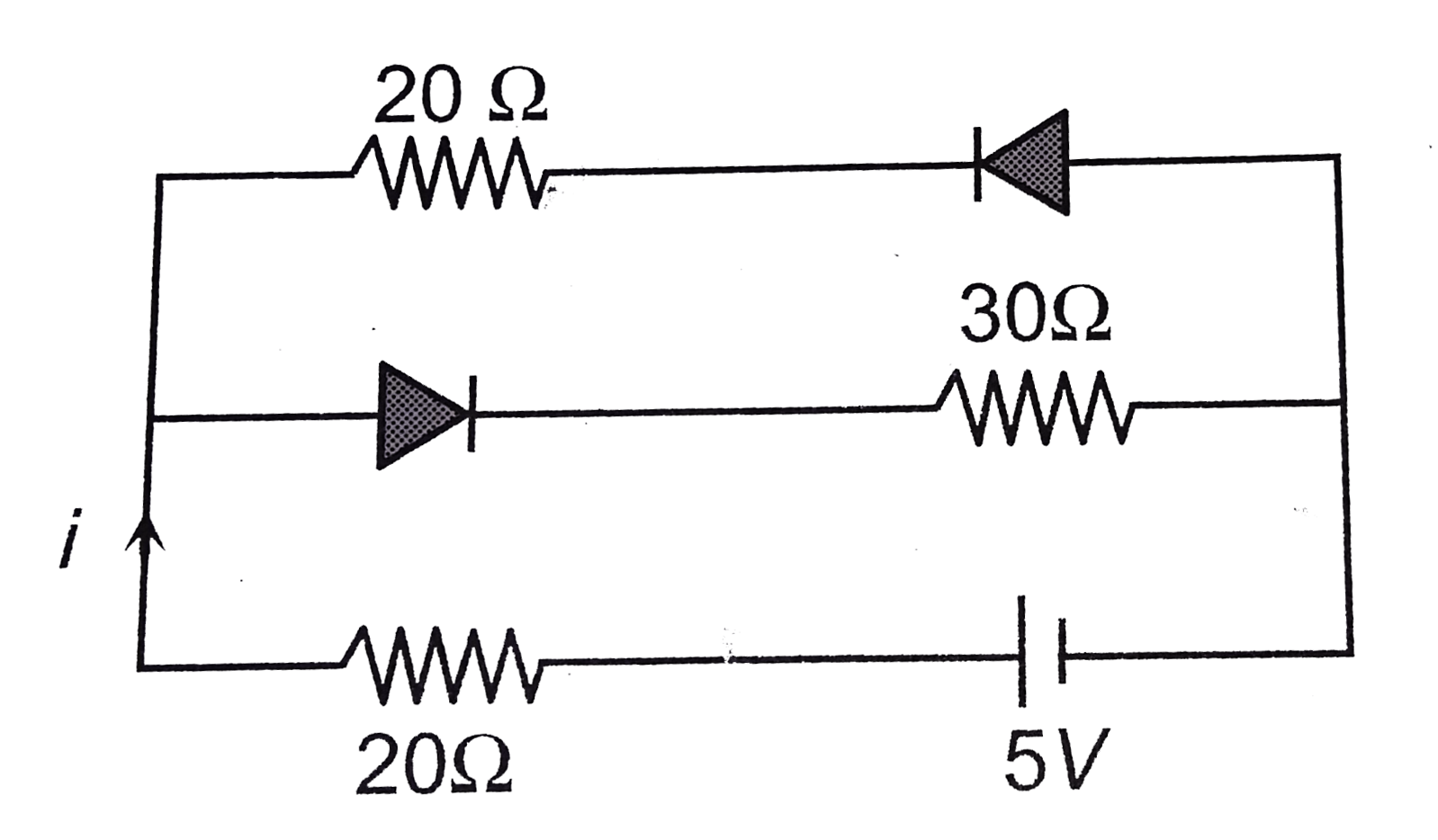
View SolutionIn the circuit given below, the value of the current is

View SolutionWhat is the current in the circuit shown below?

View SolutionIn the case of forward biasing of `PN`-junction, which one of the following figures correctely depicts the direction of flow of carriers?
View Solutionwhich of the follwing is reverse biased?
View SolutionWhich of the following is reverse biased diode?
View SolutionIn the given figure, which of the diodes are forward biased?
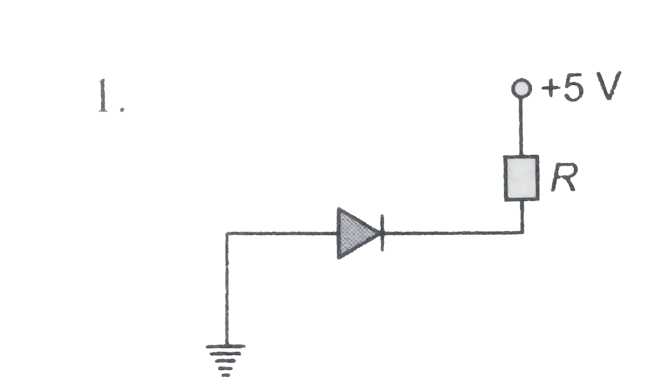
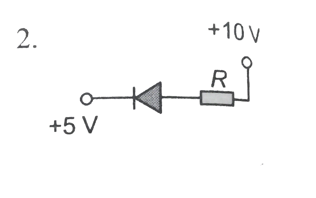
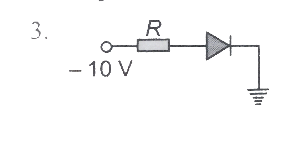
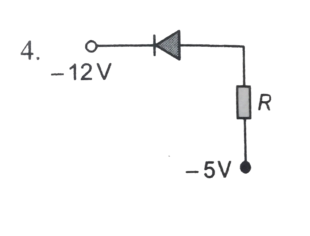
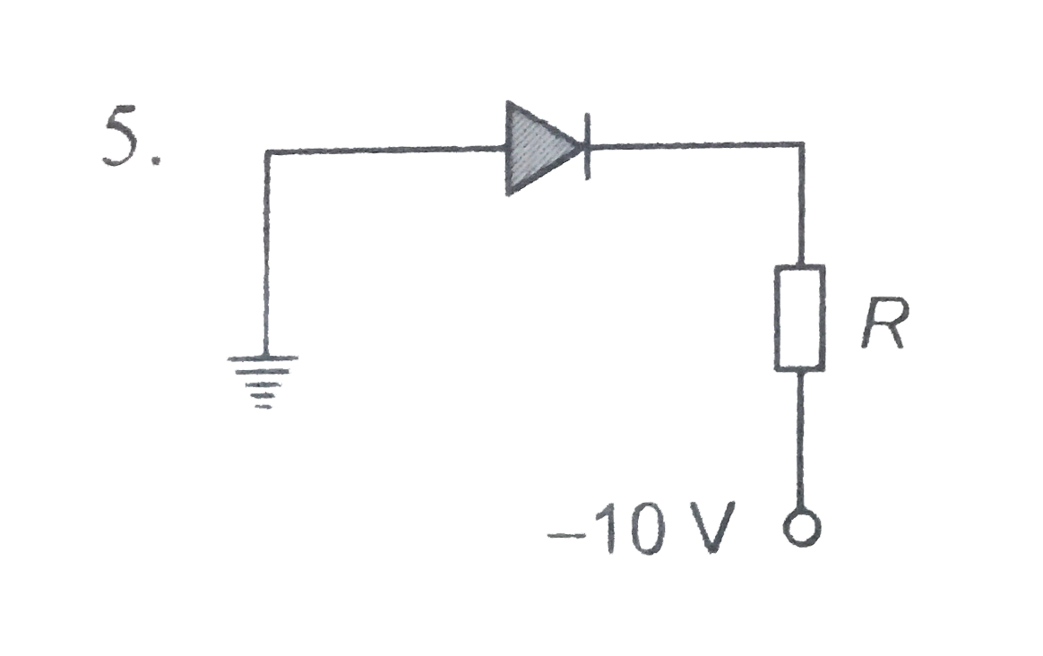
View SolutionFor the given circuit of `PN`-junction diode, which of the following statements is correct?
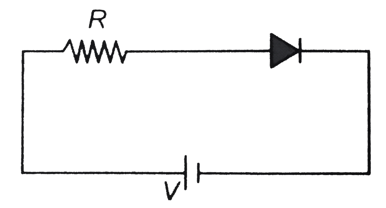
View SolutionOf the diodes shown in the following diagrams, which one is reverse biased?
View SolutionWhich is the correct diagram of a half- wave reactifier?
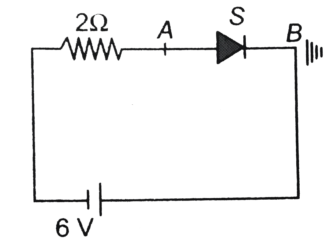
View SolutionThe diode shown in the circuit is a silicon diode. The potential difference between the points `A` and `B` will be
View SolutionThe correct symbole for Zener diode is
View SolutionWhich of the following semiconductor diodes is reverse biased?
View SolutionSymbolic representation of photodiode is
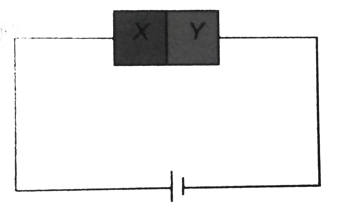
View SolutionA semiconductor `X` is made by dopping a germanium crystal with arsenic `(Z=33)`. A scond semiconductor `Y` is made by dopping germanium with indium `(Z=49)`. The two are joined end to end and connected to a battery as shown. Which of the following statements is correct?
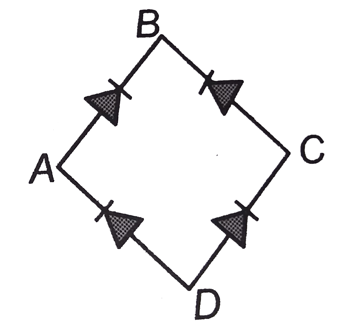
View SolutionIn the diagram, the input is across the terminals `A` and `C` and the output is across the terminals `B` and `D`, then the outputs is
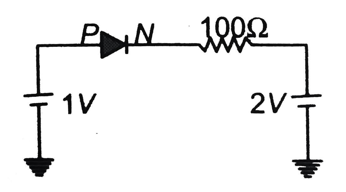
View SolutionThe current through an ideal `PN`-junction shown in the following circuit diagram will be
View SolutionIn a full wave rectifiers, input `ac` current has a frequency `'v'`. The output frequency of the current is
View SolutionA diode having potential difference `0.5 V` across its junction which does not depend on current, is connected in series with resistance of `20 Omega` across source. If `0.1A` passes through resistance then what is the voltage of the source?
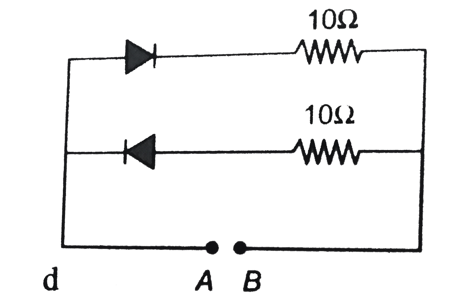
View SolutionA `2V` battery is connected across the points `A` and `B` as shown in the figure given below. Assuming that the resistance of each diode is zero in forward bias and infinity in reverese biase, the current supplied by the battery when its positive terminal is connected to `A` is
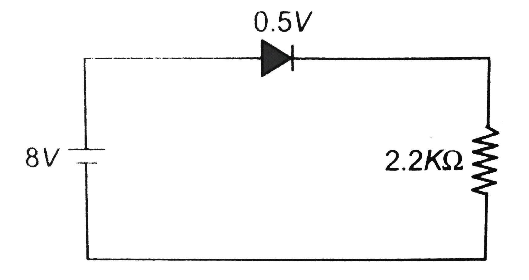
View SolutionIn the circuit, if the forward voltage drop for the diode is `0.5 V`, the current will be
View SolutionCurrent in the circuit will be
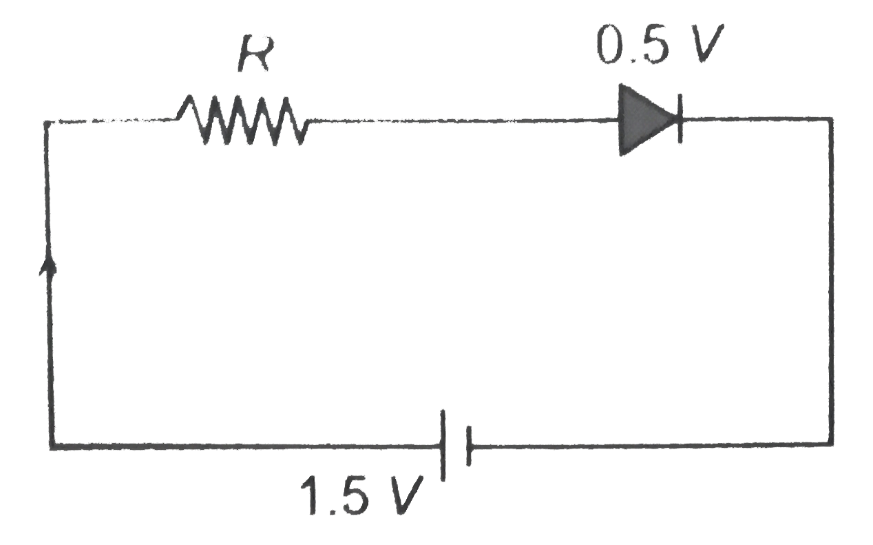
View SolutionThe diode used in the circuit shown in the figure has a constant voltage drop of `0.5 V` at all currents and a maximum power rating of `100` milliwatts. What should be the value of the resistor `R`, connected in series with the diode for obtaining maximum current?
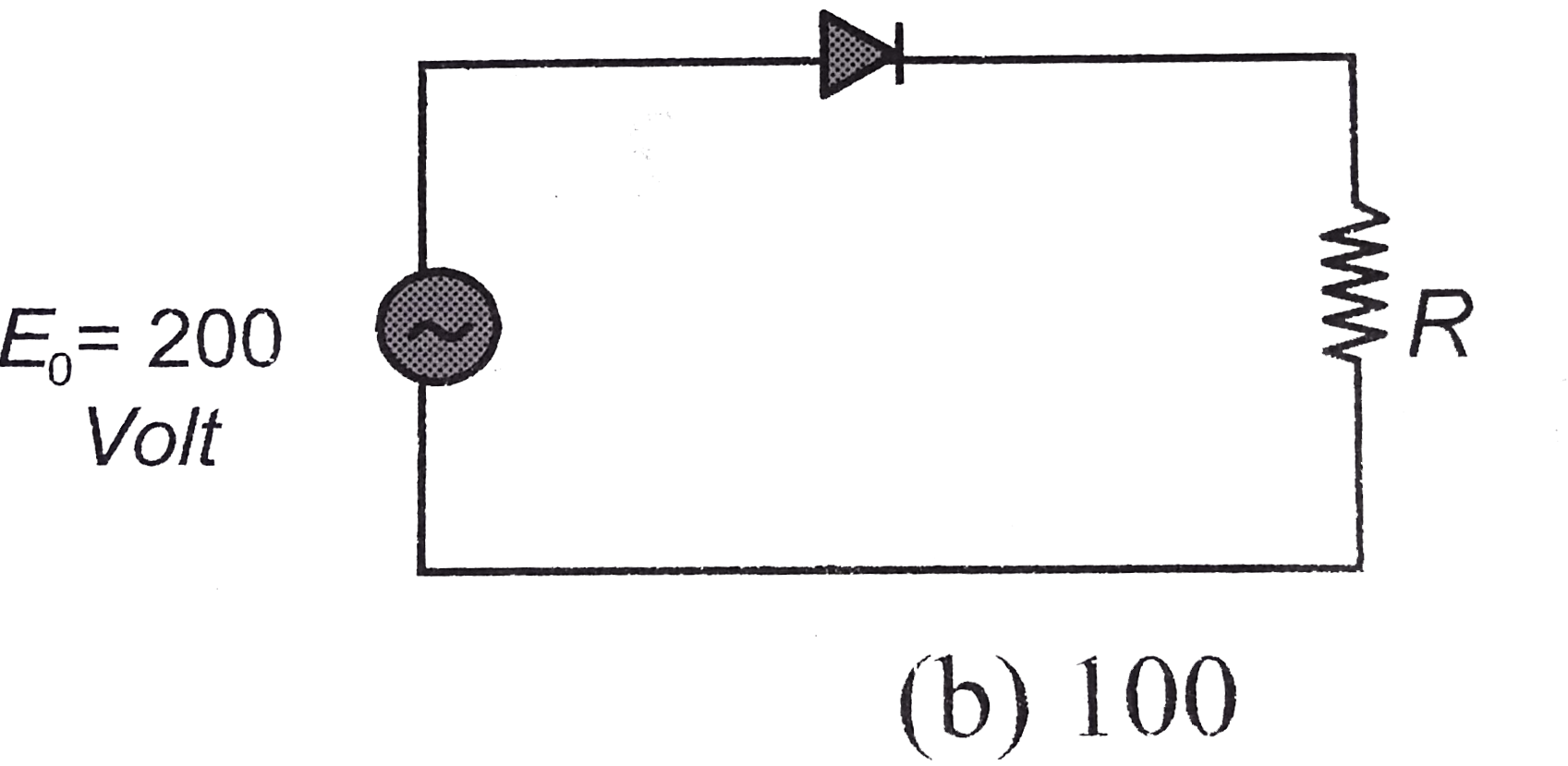
View SolutionA sinusoidal voltage of peak value `200` volts is connected to a diode and resistor `R` in the circuit shown so that half wave rectification occurs. If the forward resistance of the diode is negligible compared to `R` the `rms` voltage (in volt) across `R` is approximately
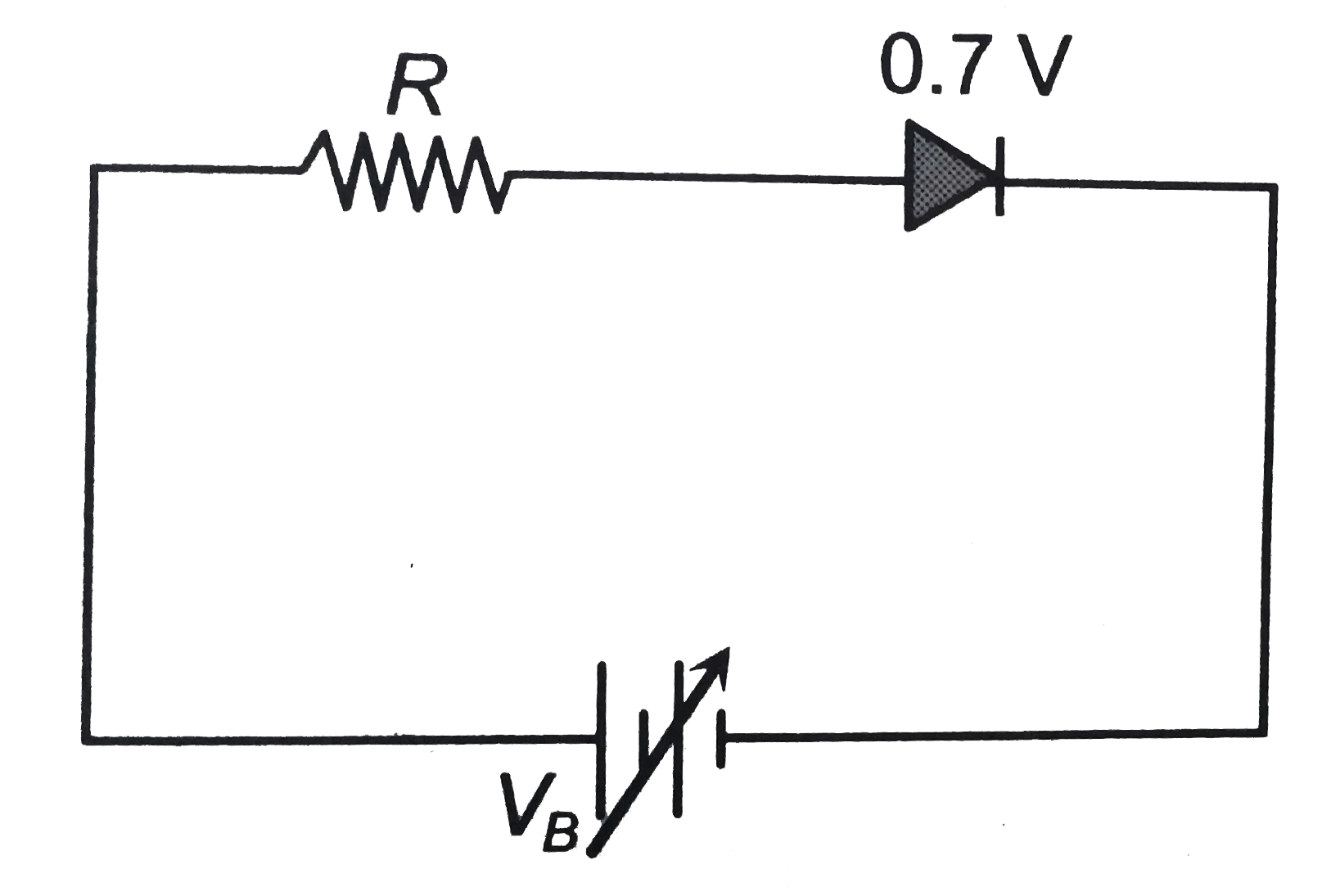
View SolutionThe junction diode in the following circuit requires a minimum current of `1 mA` to be above the knee point `(0.7 V)` of its `I-V` characterstic curve. The voltage across the diode is independent of current above the knee point. If `V_(B)=5 V`, then the maximum value of `R` so that the voltage is above the knee point, will be
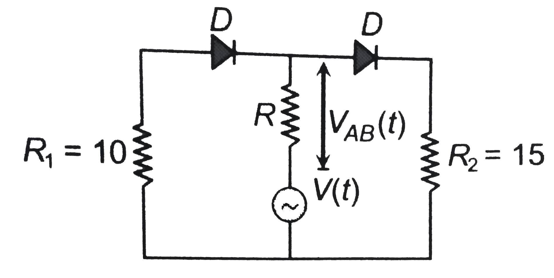
View SolutionIn the circuit given below, `V(t)` is the sinusoidal voltage source, voltage drop `V_(AB)(t)` across the resistance `R` is
View SolutionThe peak voltage in the output of a half-wave diode rectifier fed with a sinusiodal signal without filter is `10 V`. The `dc` component of the output voltage is
View SolutionIn the following circuits `PN`-junction diodes `D_(1), D_(2)` and `D_(3)` are ideal for the following potential of `A` and `B`, the correct increasing order to resistance between `A` and `B` will be
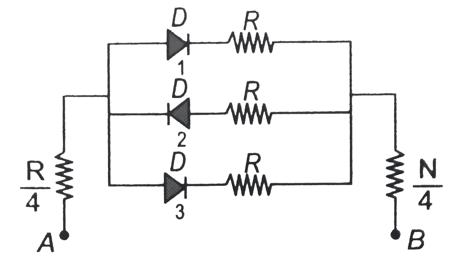
`(i) -10V, -5V (ii) -5V,-10V`
`(iii) -4V, -12V`
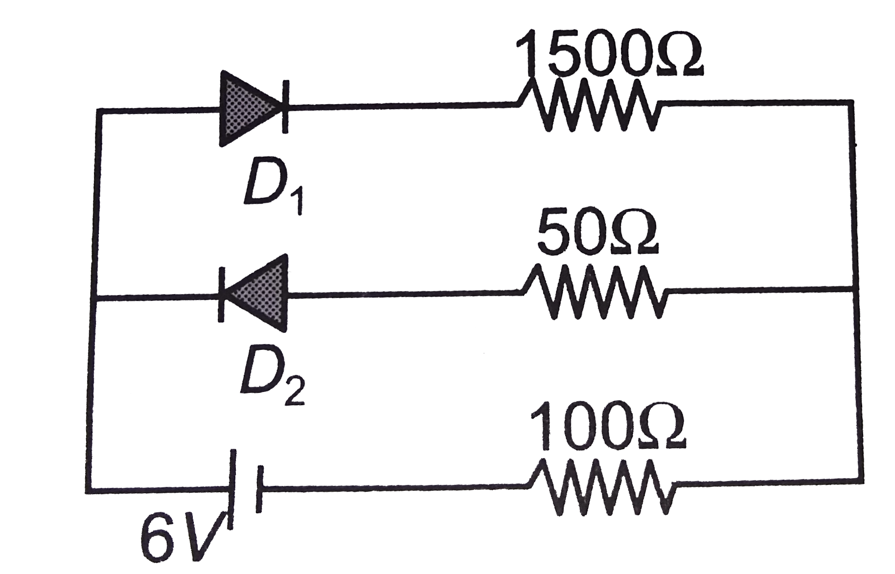
View SolutionThe circuit shown in following figure contains two diode `D_(1)` and `D_(2)` each with a forward resistance of `50 ohm` and with infinite backward resistance. If the battery voltage is `6V`, the current through the `100` ohm resistance (in amperes) is
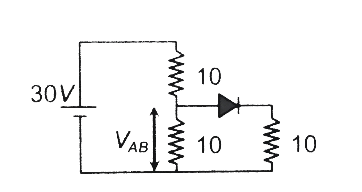
View SolutionFind `V_(AB)`
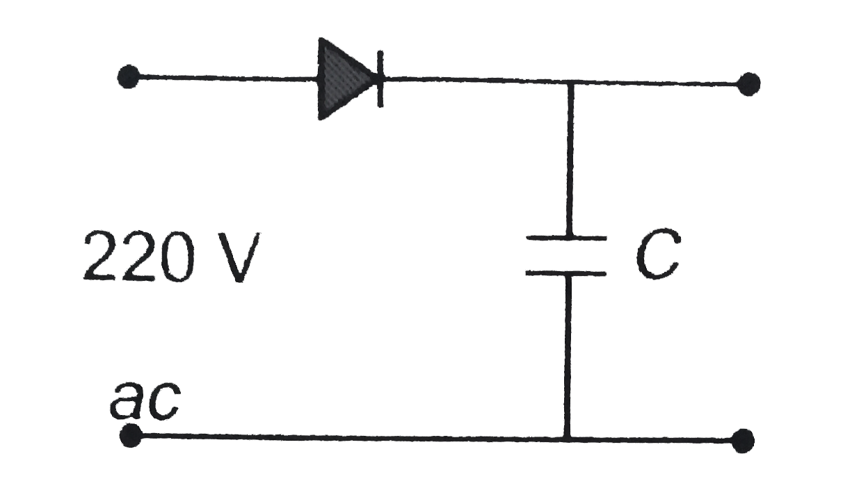
View SolutionA diode is connected to `220V (rms)` `ac` in series with a capacitor as shown in fig. The voltage across the capacitor is
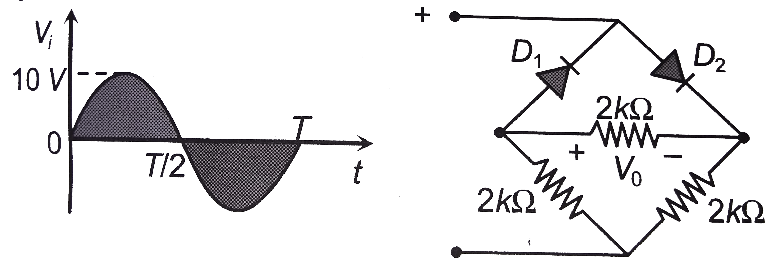
View SolutionIn the circuit shown in figure the maximum output voltage `V_(0)` is
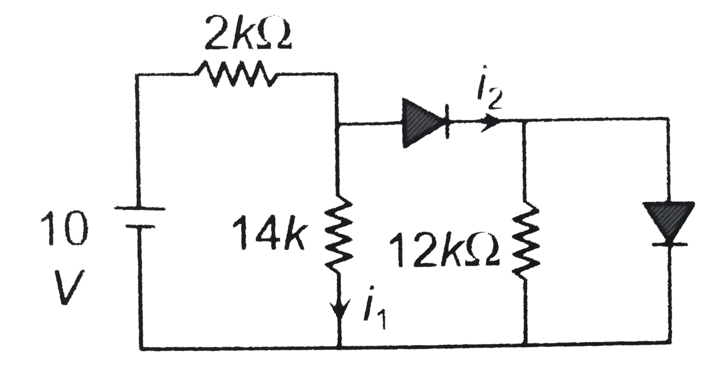
View SolutionIn the following circuit find `I_(1)` and `I_(2)`
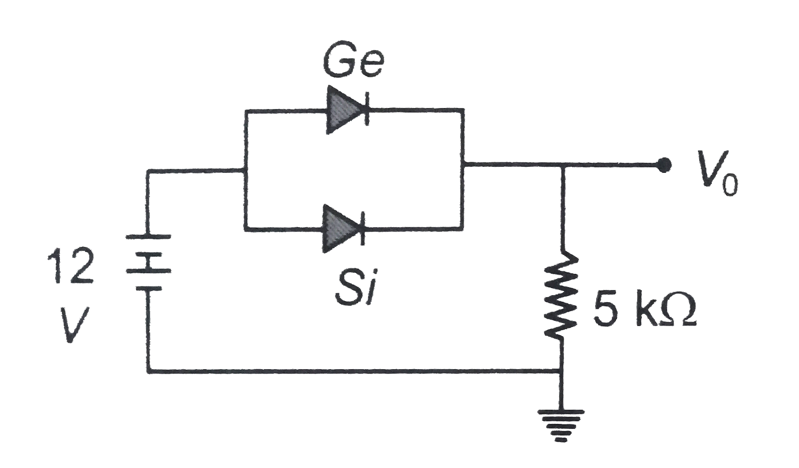
View Solution`Ge` and `Si` diodes conduct at `0.3 V` and `0.7 V` respectively. In the following figure if `Ge` diode connection are reversed, the value of `V_(0)` changes by
View SolutionIn the following circuit `I_(1)` and `I_(2)` are respectively
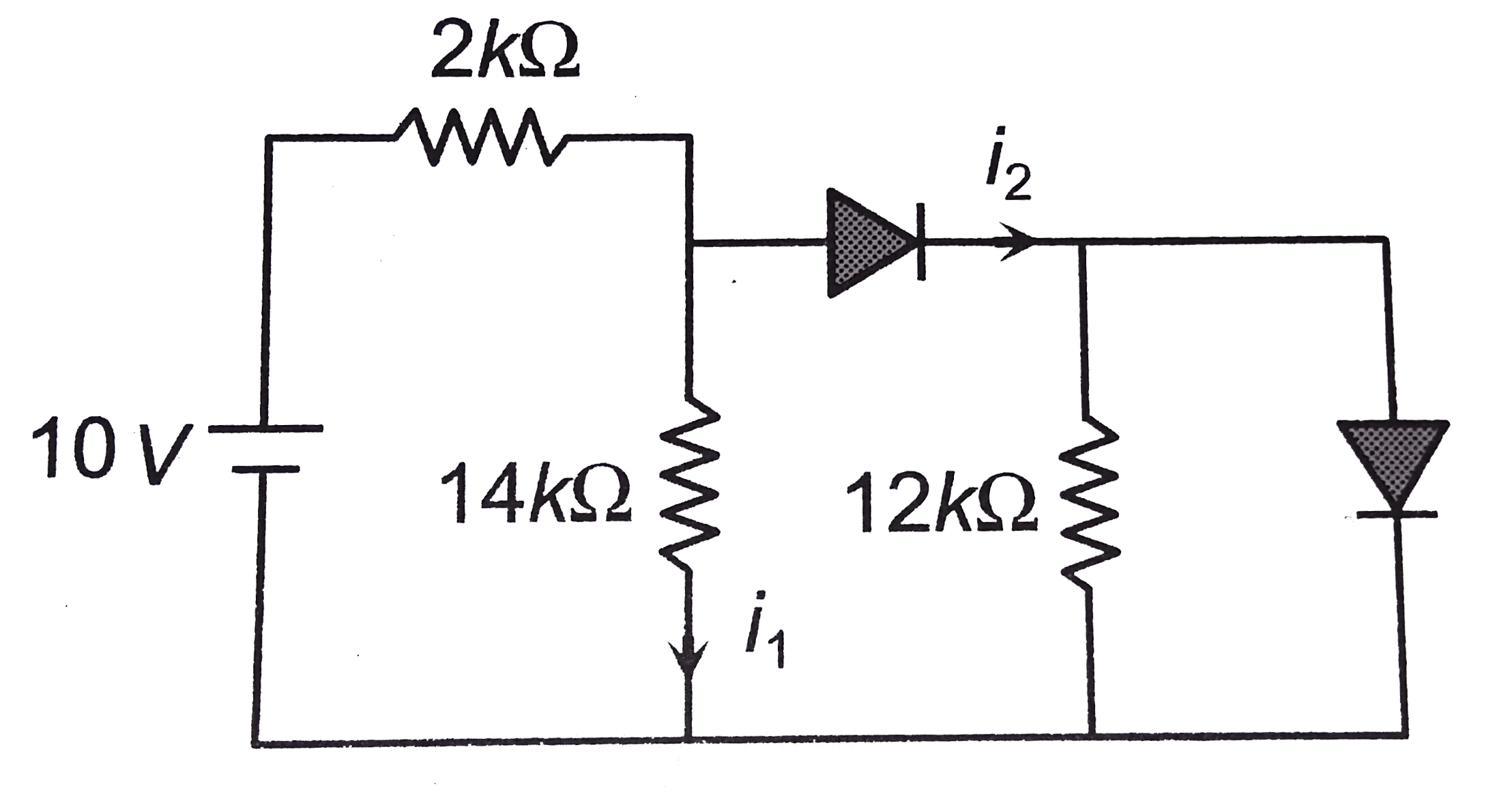
View SolutionIn space charge limited region, the plate current in a diode is `10 mA` for a plate voltage `150 V`. If the plate voltage is increased to `600 V`, then the plate current will be
View SolutionWhen a silicon `PN` junction is in forwards biased condition with series resistance, it has knee voltage of `0.6 V`. Current flow in it is `5 mA`, when `PN` junction is connected with `2.6 V` battery, the value of series resistance is
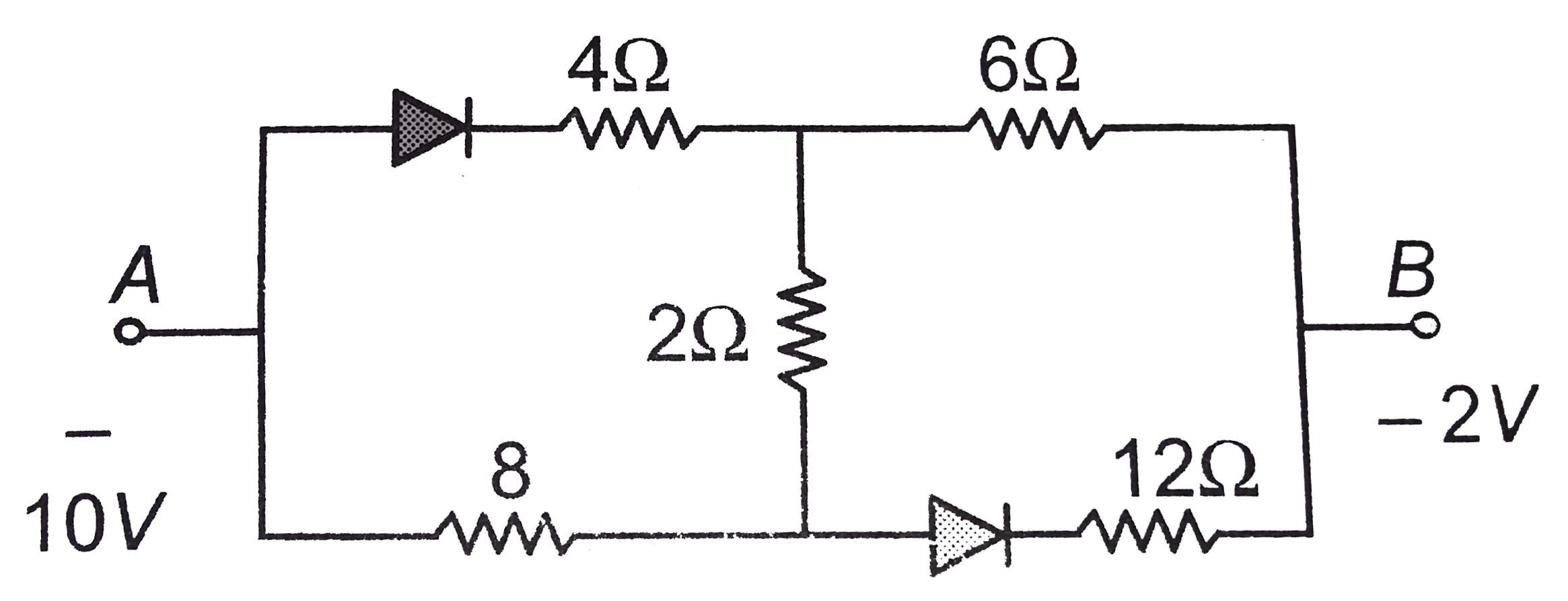
View SolutionIn the following circuit the equivalent resistance between `A` and `B` is
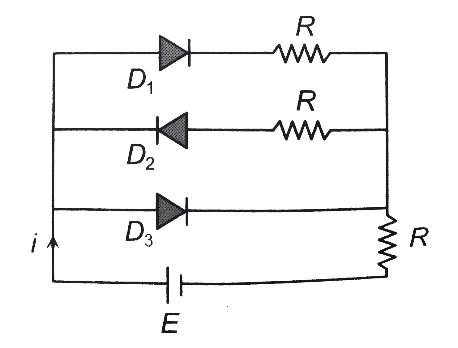
View SolutionIn the following circuit of `PN` junction diodes `D_(1),D_(2)` and `D_(3)` are ideal then `i` is
View SolutionA waveform shown when applied to the following circuit will produce which of the following output waveform? [Assuming ideal diode configuration and `R_(1)=R_(2)`]

View Solution
Diode In Circuits questions and complete solutions for chapter SEMICONDUCTOR ELECTRONICS of A2Z PHYSICS (HINGLISH) of Class 12