Complete Solutions to Exercise (single Correct ) of chapter SOURCES OF MAGNETIC FIELD of Class 12 book with complete answers and questions
| Class 12 | PHYSICS |
| Chapter | SOURCES OF MAGNETIC FIELD |
| CENGAGE PHYSICS | Exercise (single Correct ) |
| Number Of Questions | 75 |
| Academic Year | 2023-24 |
A stream of electrons is projected horizontally to the right. A straight conductor carrying a current is supported parallel to the electron steam an above it. If the current in the conductor is from left to right, what will be the effect on the electron stream?
View SolutionA charge q coulomb moves in a circle at n revolution per second and the radius of the circle is r metre. Then magnetic feild at the centre of the circle is
View SolutionAn electron is ejected from the surface of a long, thick straight conductor carrying a current, initially in a direction perpendicular to the conductor. The electron will
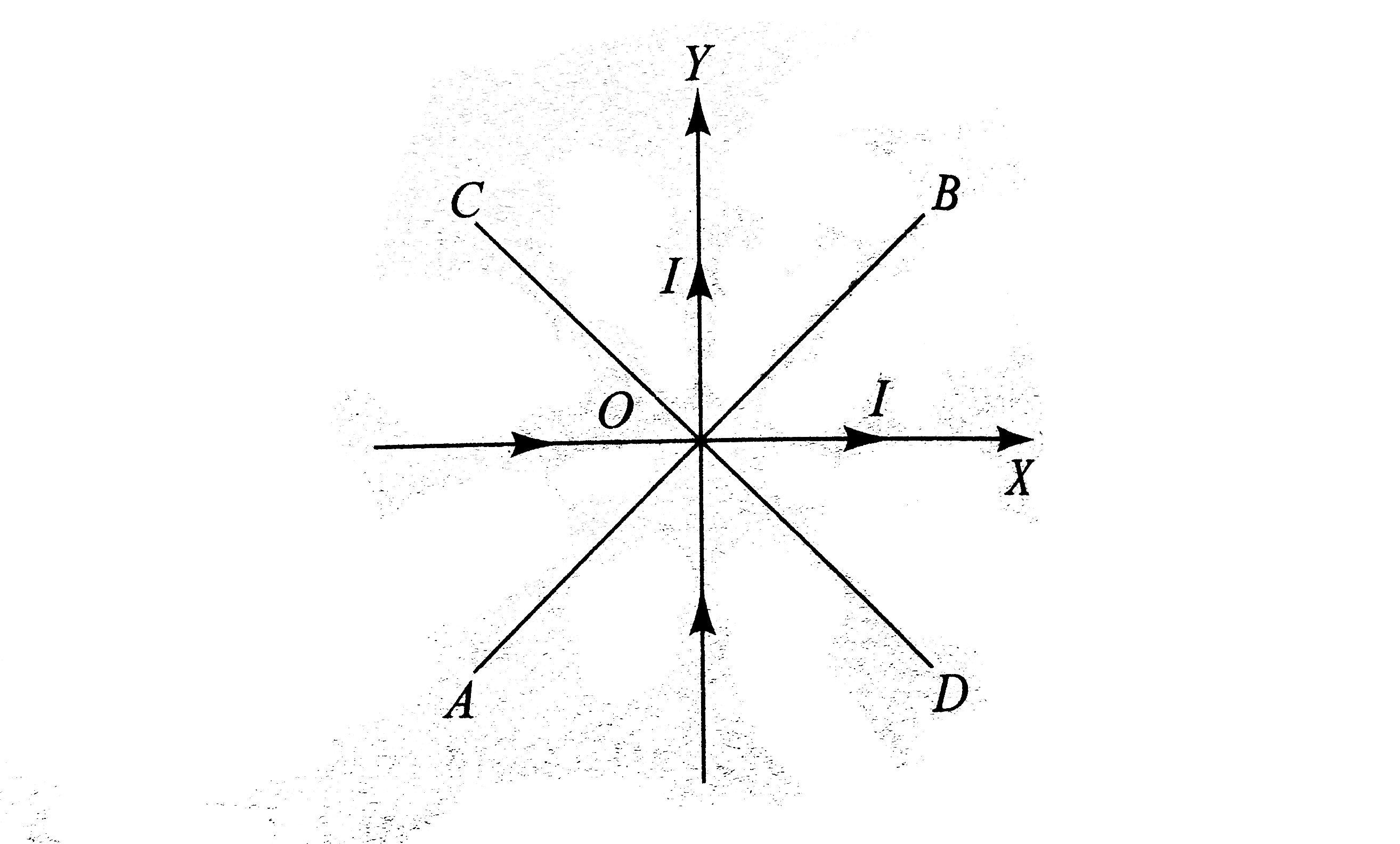
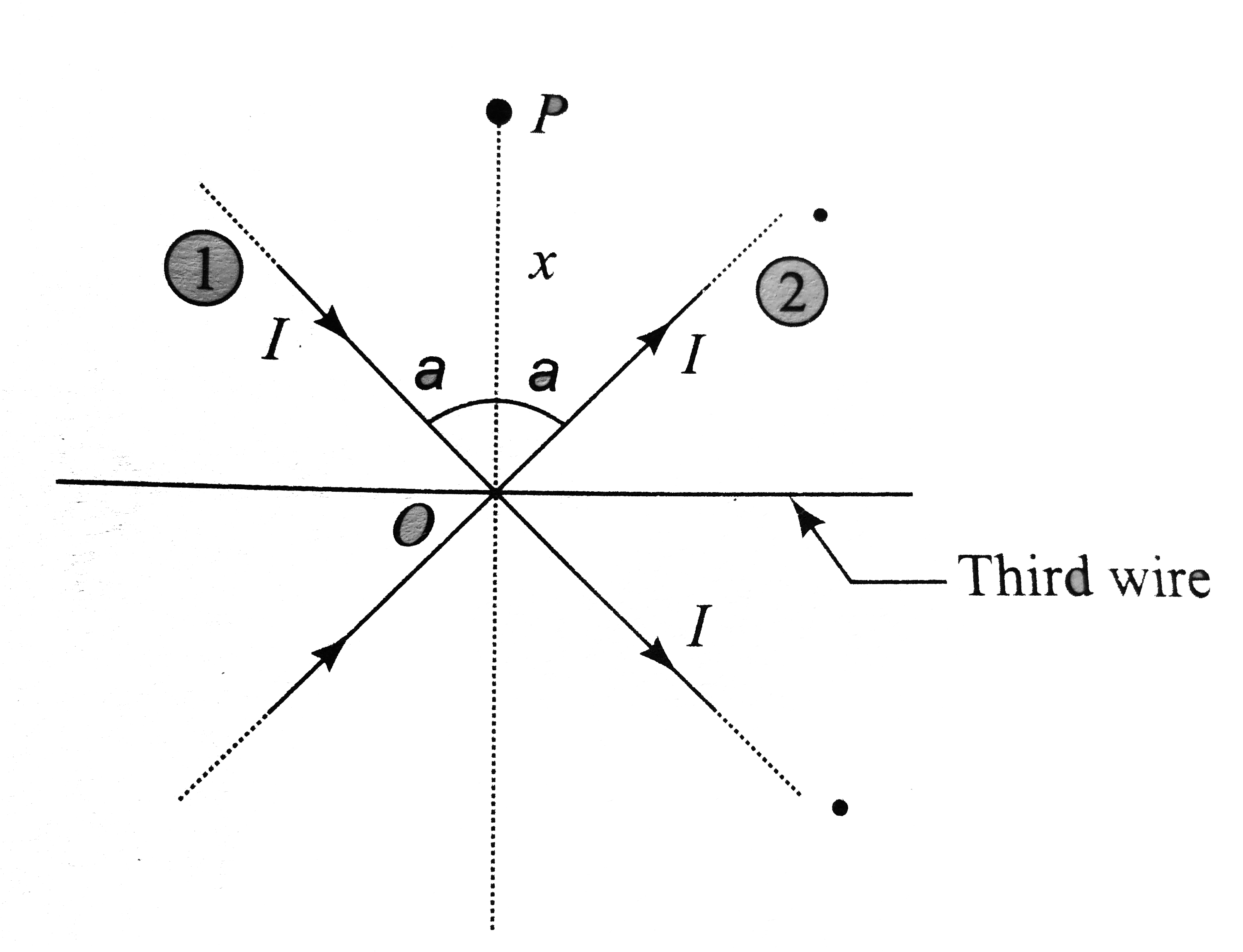
View SolutionTwo very thin metallic wires placed along X- and Y-axes carry equal currents as shown in Fig. AB and CD are lines at `45^@` with the axes. The magnetic field will be zero on the line
View SolutionA circular current-carrying coil has a radius `R`. The distance from the centre of the coil, on the axis, where `B` will be `1//8` of its value at the centre of the coil is
View SolutionA square conducting loop of side length L carries a current I.The magnetic field at the centre of the loop is
View SolutionA current of `1//(4pi)` ampere is flowing in a long straight conductor. The line integral of magnetic induction around a closed path enclosing the current carrying conductor is
View SolutionA circular loop is kept in that vertical plane which contains the north- south direction. It carries a current that is towards north at the topmost point. Let A be a point on the axis of the circle to the east of it and B a point on this axis to the west of it. The magnetic field due to the loop.
View SolutionA current i is uniformly distributed over the cross section of a long hollow cylinderical wire of inner radius `R_1` and outer radius `R_2`. Magnetic field B varies with distance r form the axis of the cylinder is
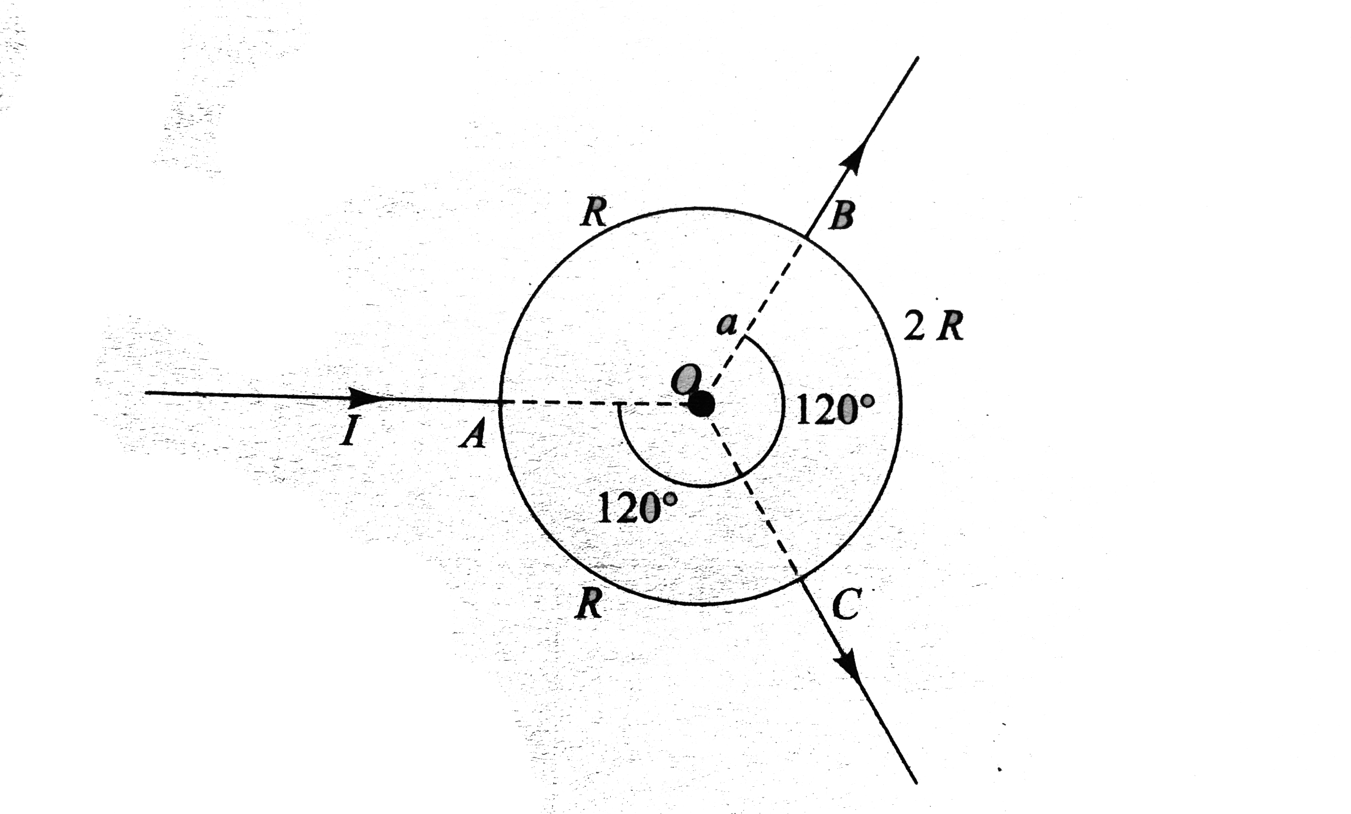
View SolutionThe resistances of three parts of a circular loop are as shown in Fig. The magnetic field at the centre O is (current enters at A and leaves at B and C as shown)
View SolutionFive very long, straight insulated wires are closely bound together to form a small cable. Currents carried by the wires are: `I_1=20A, I_2=-6A, I_3=12A, I_4=-7A, I_5=18A`. (Negative currents are opposite in direction to the positve.) The magnetic field induction at a distance of 10cm from the cable is (current enters at A and leaves at B and C as shown)
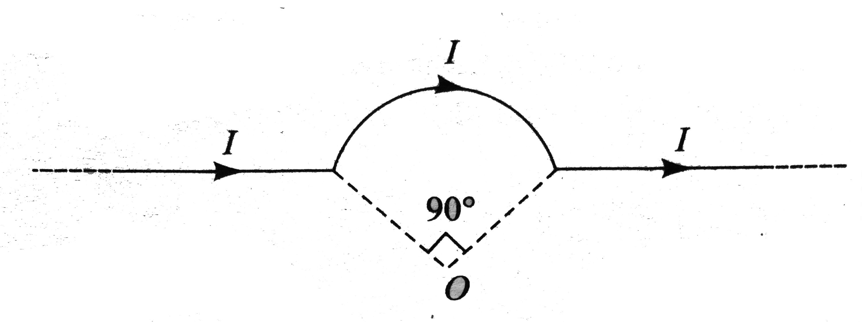
View SolutionThe magnetic induction at centre O Fig.
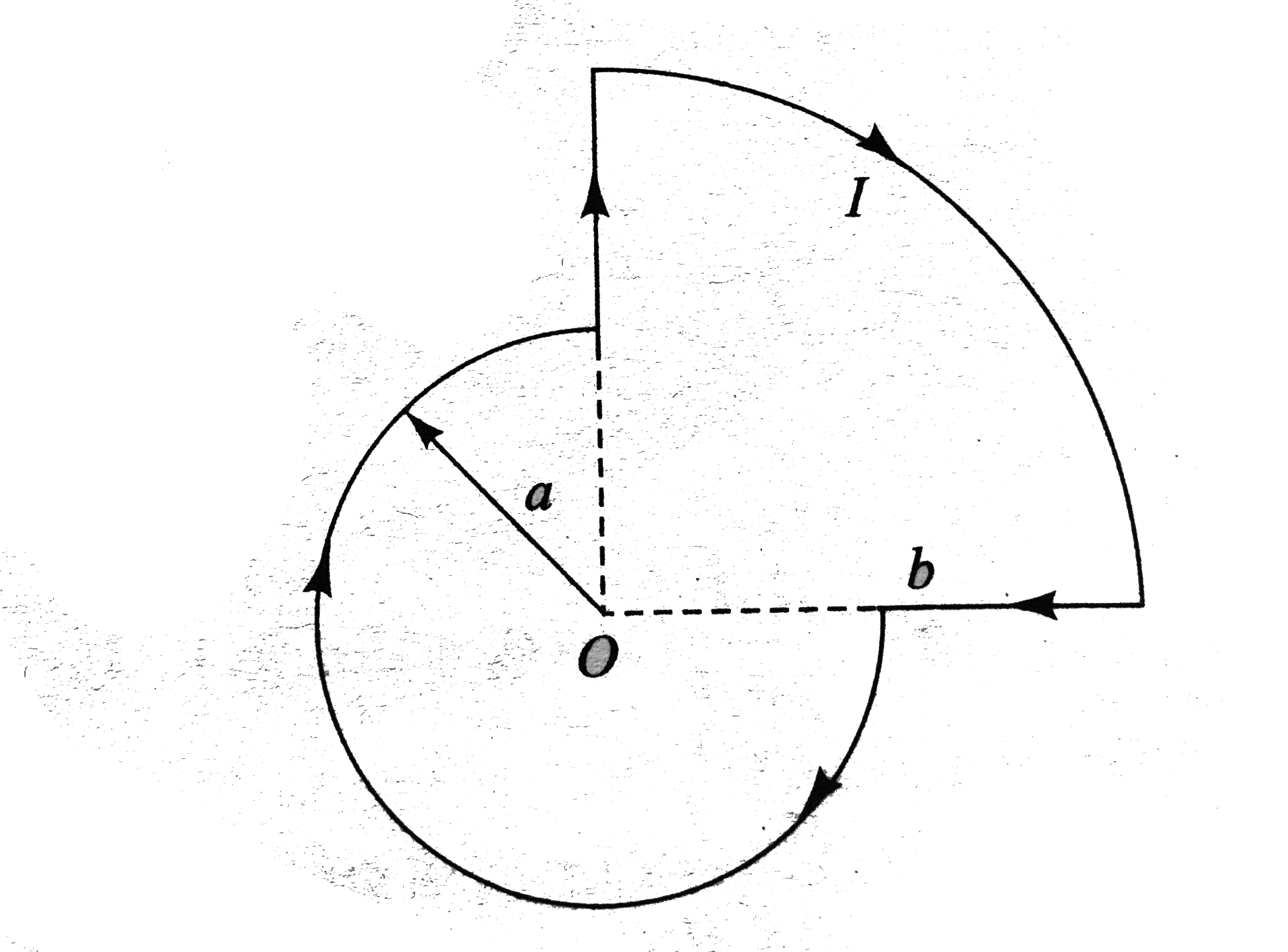
View SolutionThe magnetic field at centre O of the arc in Fig.
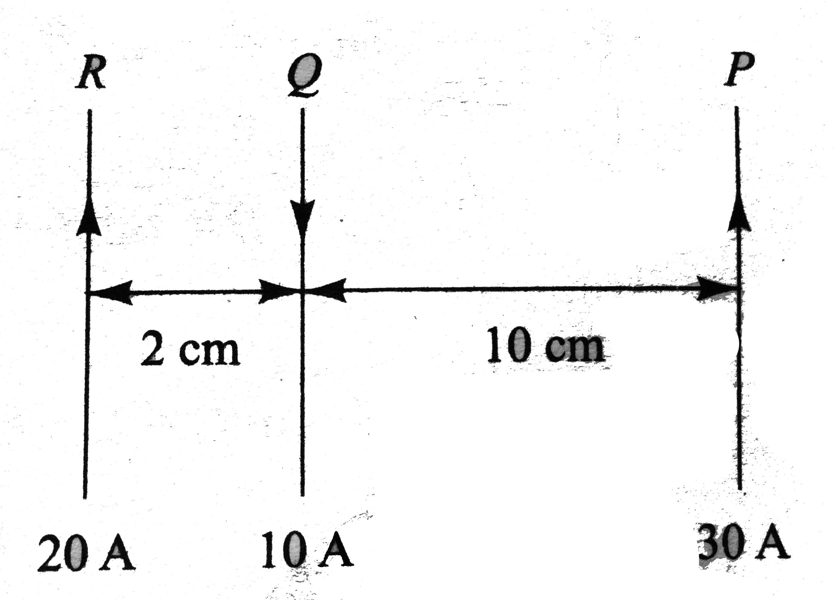
View SolutionThree long, straight and parallel wires are arranged as shown in Fig. The forces experienced by 10 cm length of wire Q is
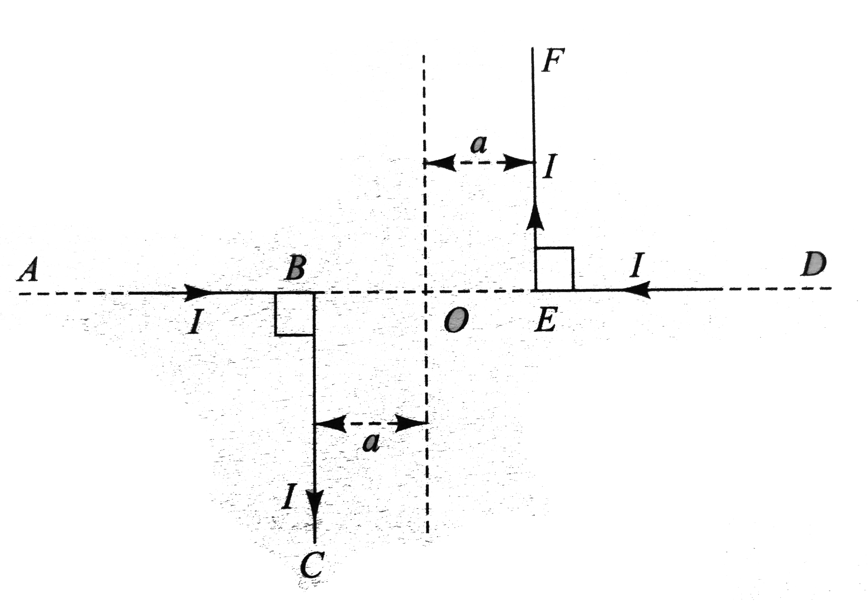
View SolutionTwo long thin wires ABC and DEF are arranged as shown in Fig. They carry equal currents I as shown. The magnitude of the magnetic field at O is
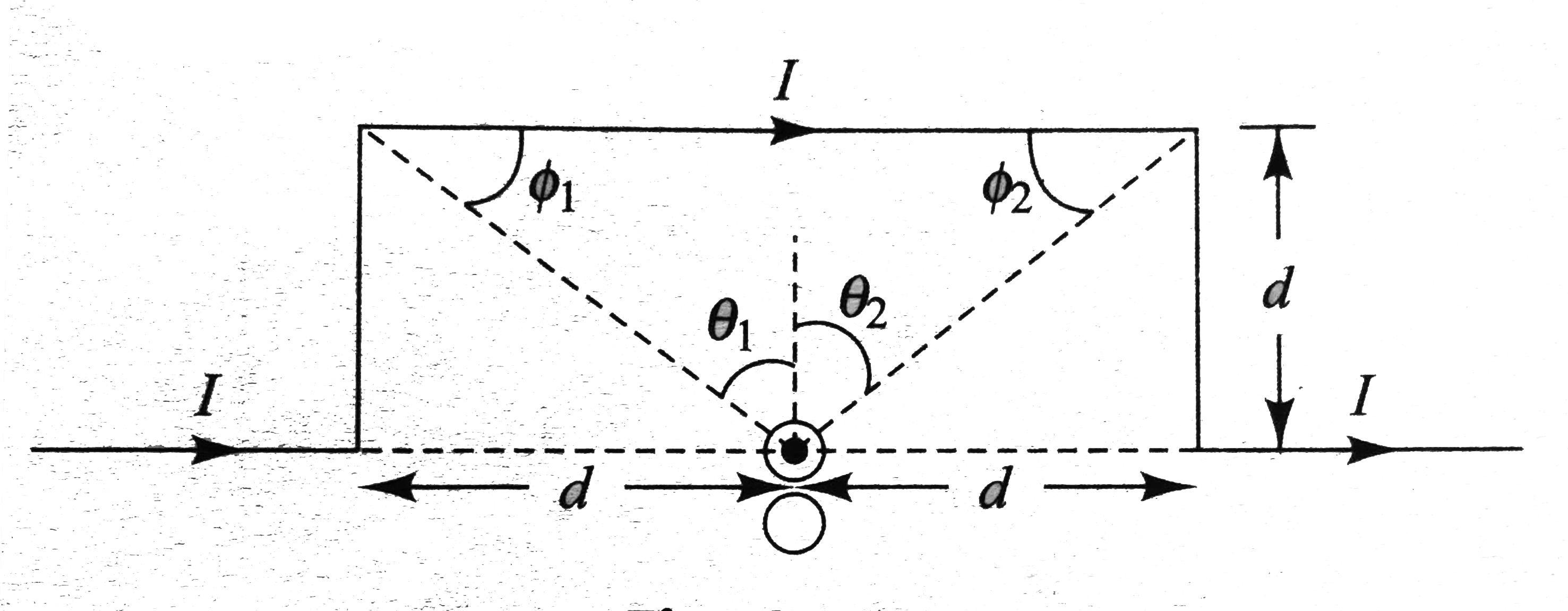
View SolutionThe magnetic field at O due to current in the infinite wire forming a loop as a shown in Fig.
View SolutionA current I flows through a thin wire shaped as regular polygon of n sides which can be inscribed in a circle of radius R. The magnetic fidl induction at the center of polygon due to one side of the polygon is
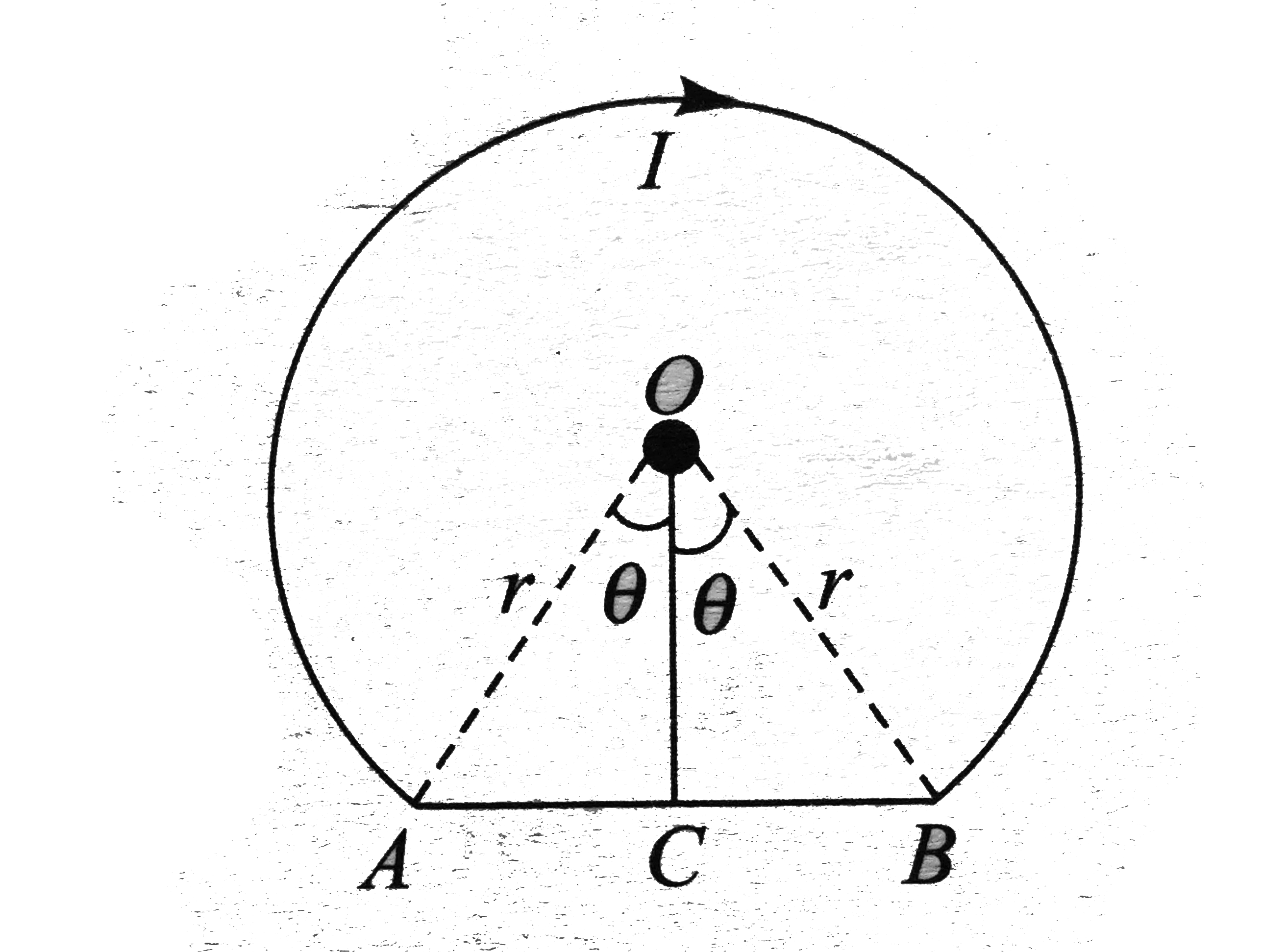
View SolutionA wire is bent in the form of a circular arc with a straight portion AB. Magnetic induction at O when current flowing in the wire, is
View SolutionThe field due to a wire of n turns and radius r which carries a current I is measure on the axis of the coil at a small distance h form the centre of the coil. This is smaller than the field at the centre by the fraction:
View SolutionTwo identical wires A and B have the same length l and carry the same current I. Wire A is bent into a circle of radius R and wire B is bent to form a square of side a. If `B_1 and B_2` are the values of magnetic induction at the centre of the circle and the centre of the square, respectively, then the ratio `B_1//B_2` is
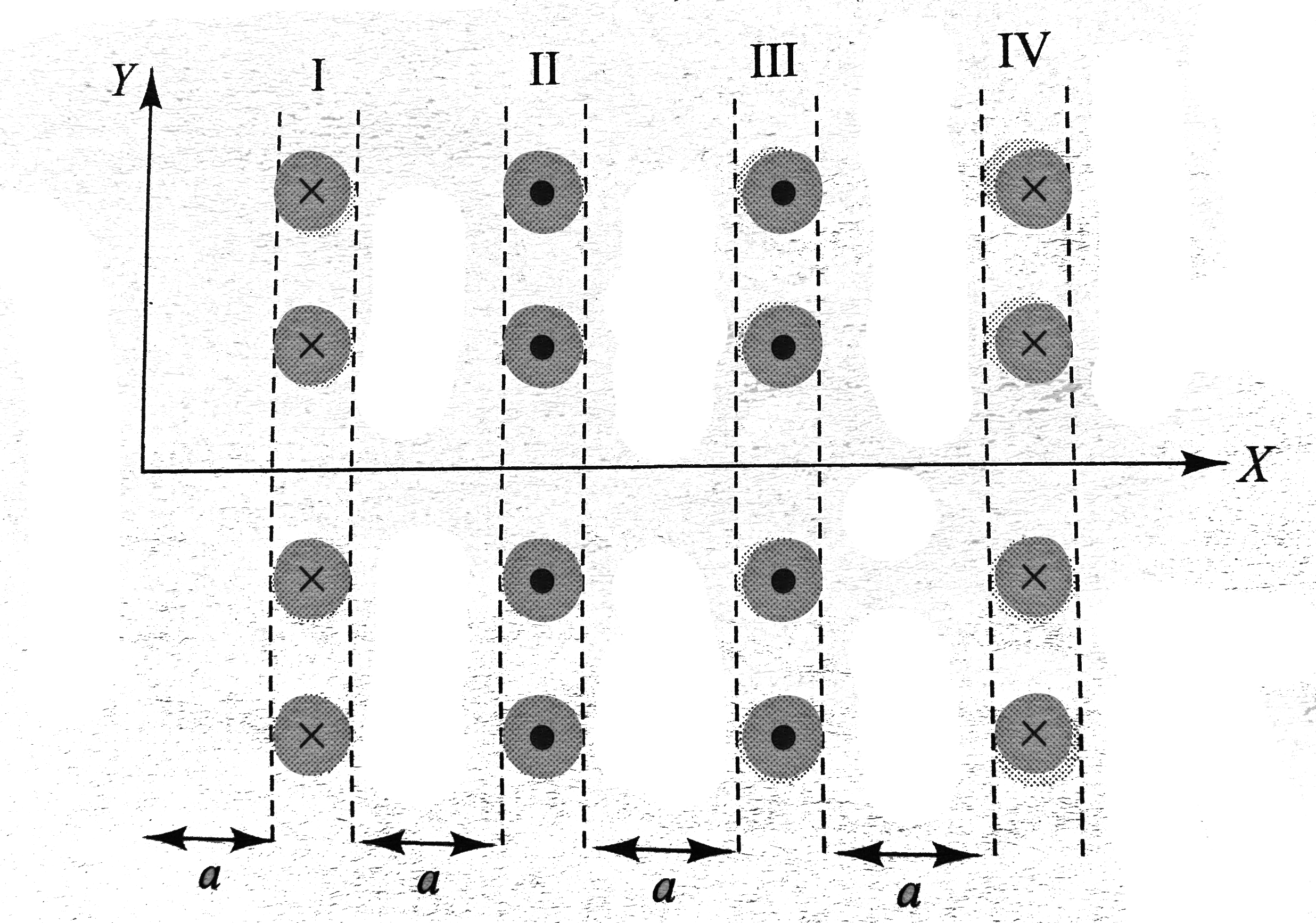
View SolutionFour infinite thin current carrying sheets are placed in Y-Z plane. The 2D view of the arrangement is as shown in Fig. Direction of current has alos been shown in the figure. The linear current density, i.e., current per unit width in the four sheets are I, 2I, 3I, and 4I, respectively.
View SolutionA steady current is flowing in a circular coil of radius R, made up of a thin conducting wire. The magnetic field at the centre of the loop is `B_L`. Now, a circular loop of radius `R//n` is made from the same wire without changing its length, by unfounding and refolding the loop, and the same current is passed through it. If new magnetic field at the centre of the coil is `B_C`, then the ratio `B_L//B_C` is
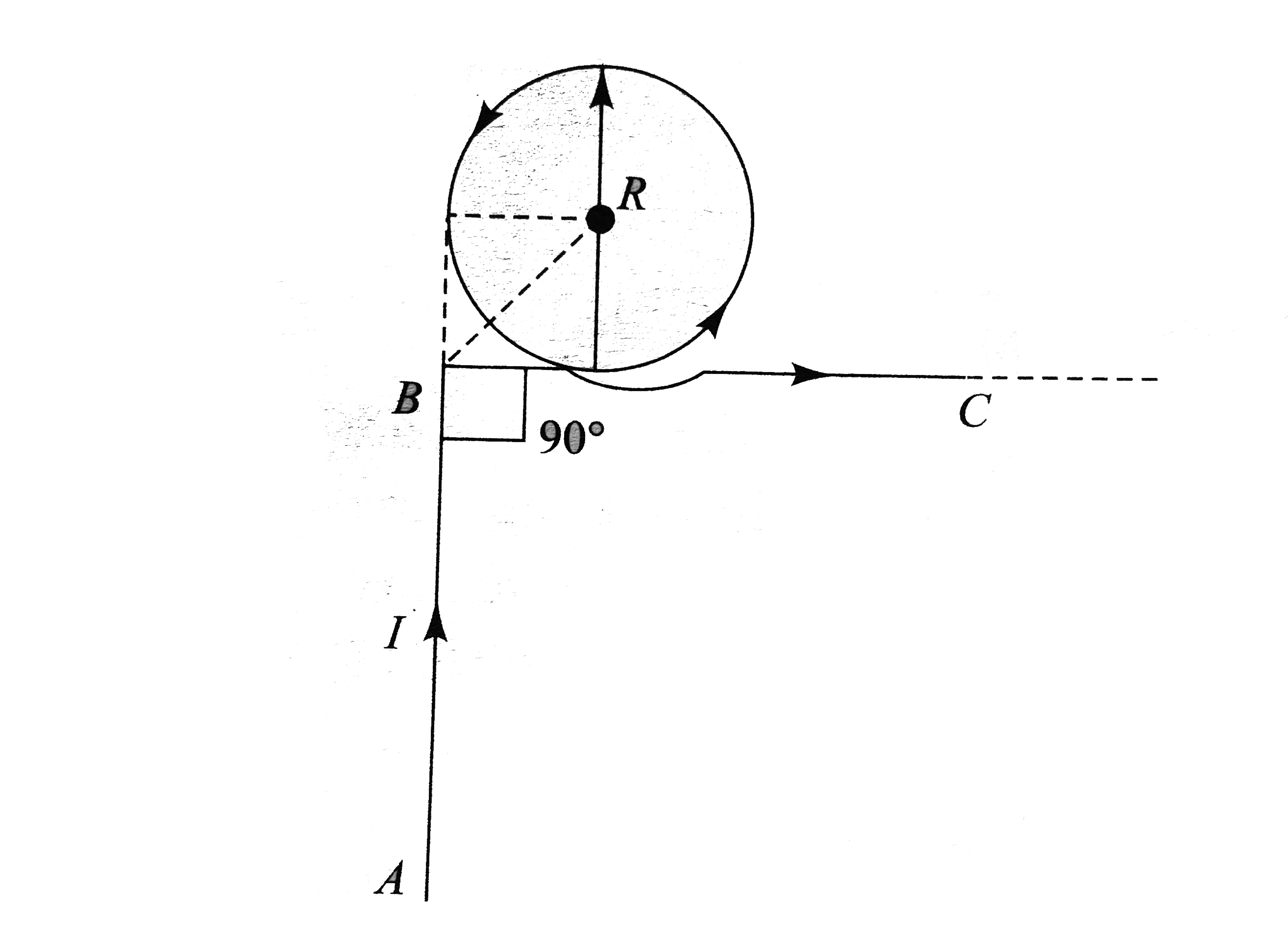
View SolutionThe magnetic field at the centre of the circular loop as shown in Fig. when a single wire is bent to form a circular loop and also extends to form straight sections is
View SolutionTwo parallel wire carrying equal currents in opposite directions are placed at `x=+-a` parralel to y-axis with `z=0`. Magnetic field at origin O is `B_1` and at `P(2a,0,0) is B_2`. Then, the ratio `B_1//B_2` is
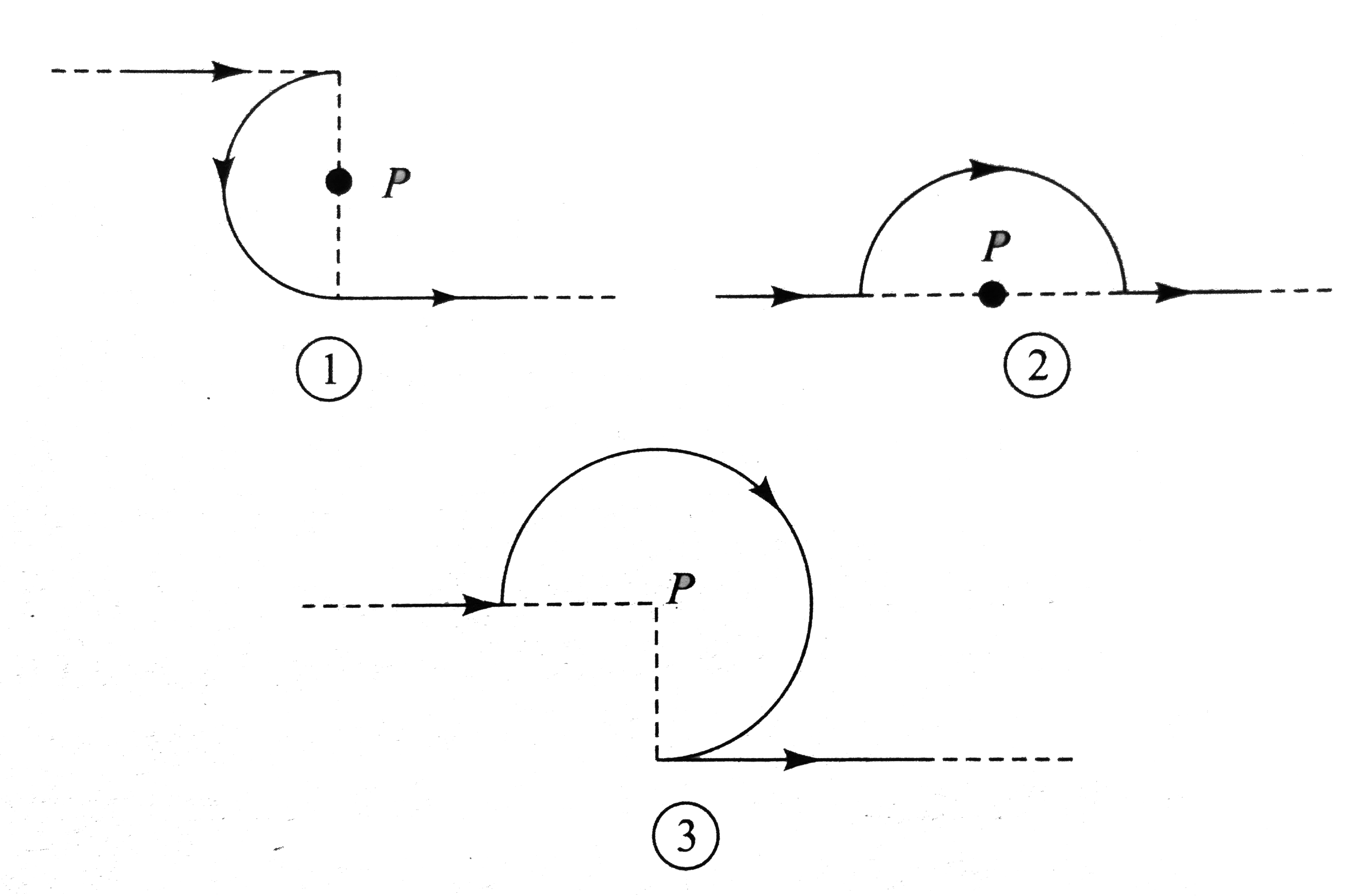
View SolutionFigure shows three cases: in all case the circular part has radius r and straight ones are infinitely long. For the same current the ratio of field B at centre P in the three case `B_1:B_2:B_3` is
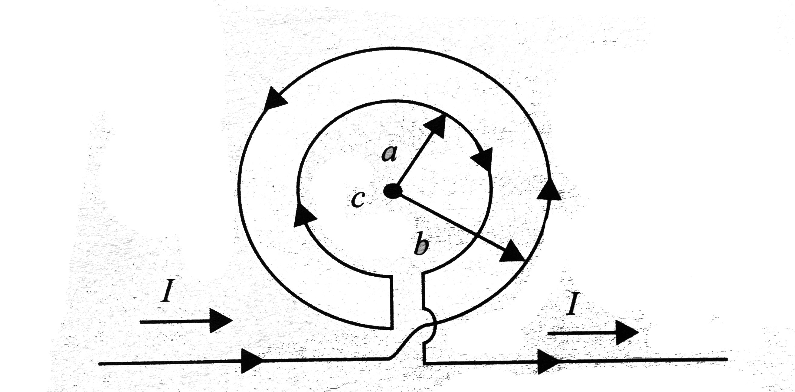
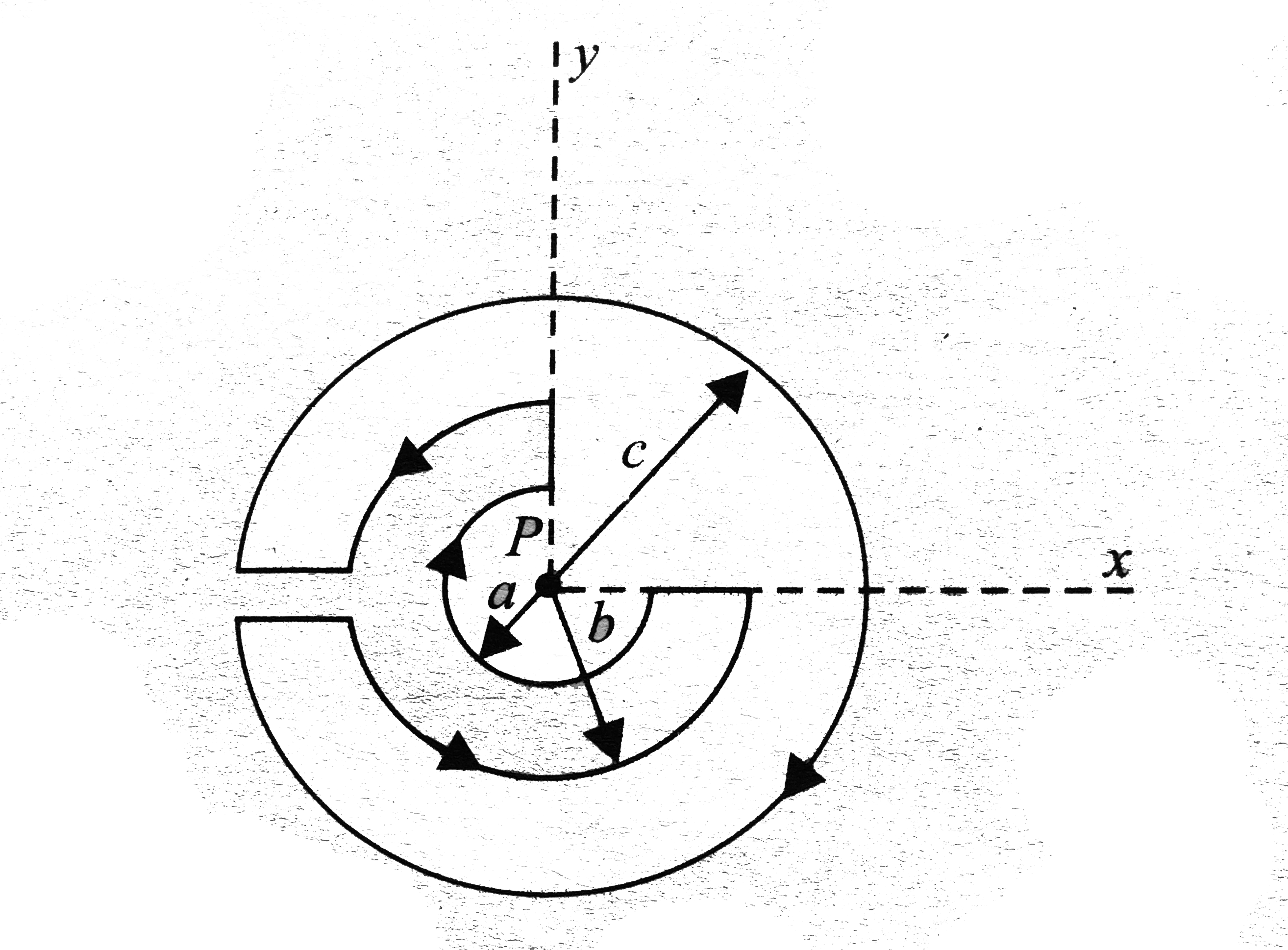
View SolutionAn otherwise infinite, straight wire has two concentric loops of radii a and b carrying equal currents in opposite directions as shown in Fig. The magnetic field at the common centre is zero for
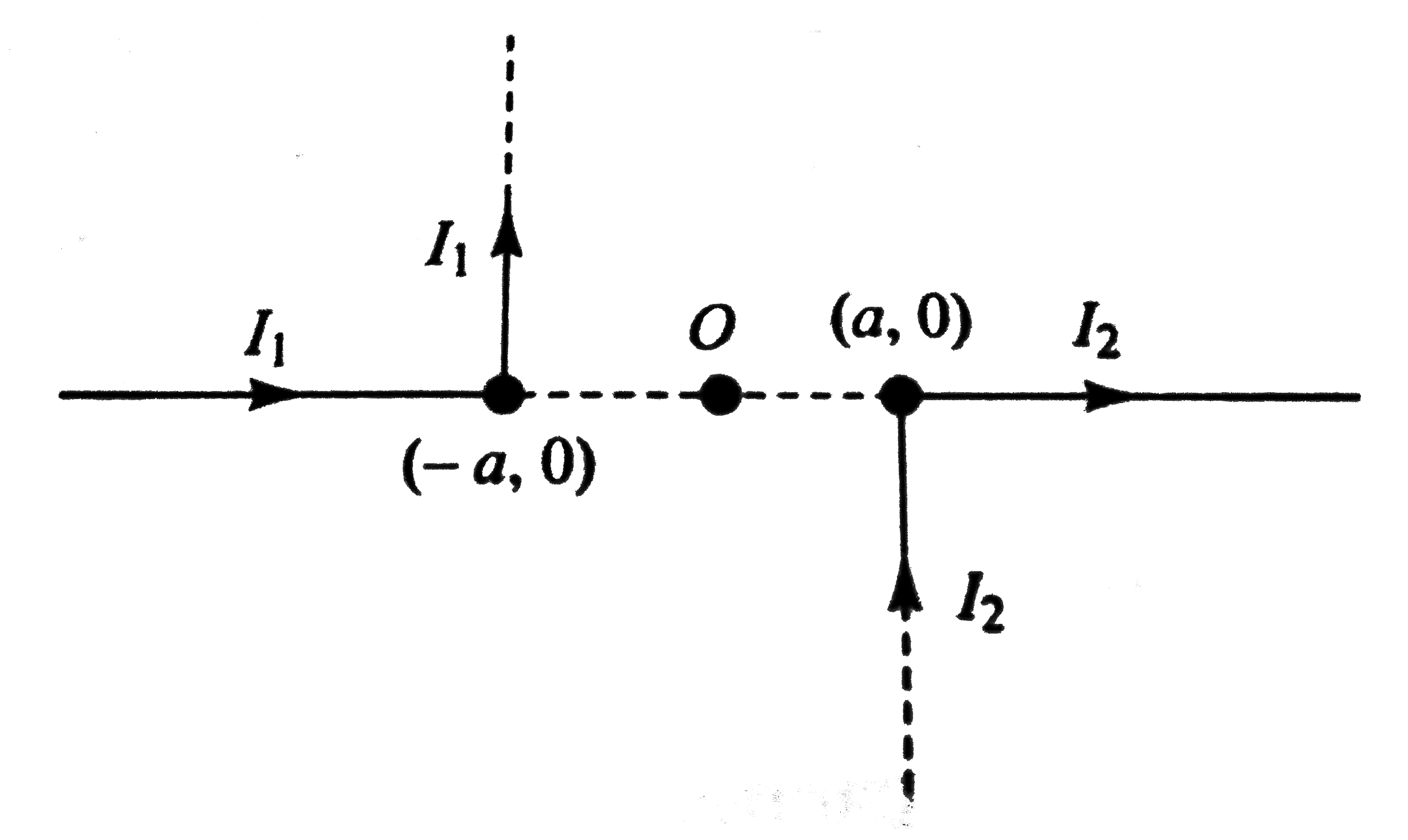
View SolutionCurrent `I_1 and I_2` flow in the wires shown in Fig. The field is zero at distance x to the right of O. Then
View SolutionFor `c=2a` if, the magnetic field at point P will be zero when
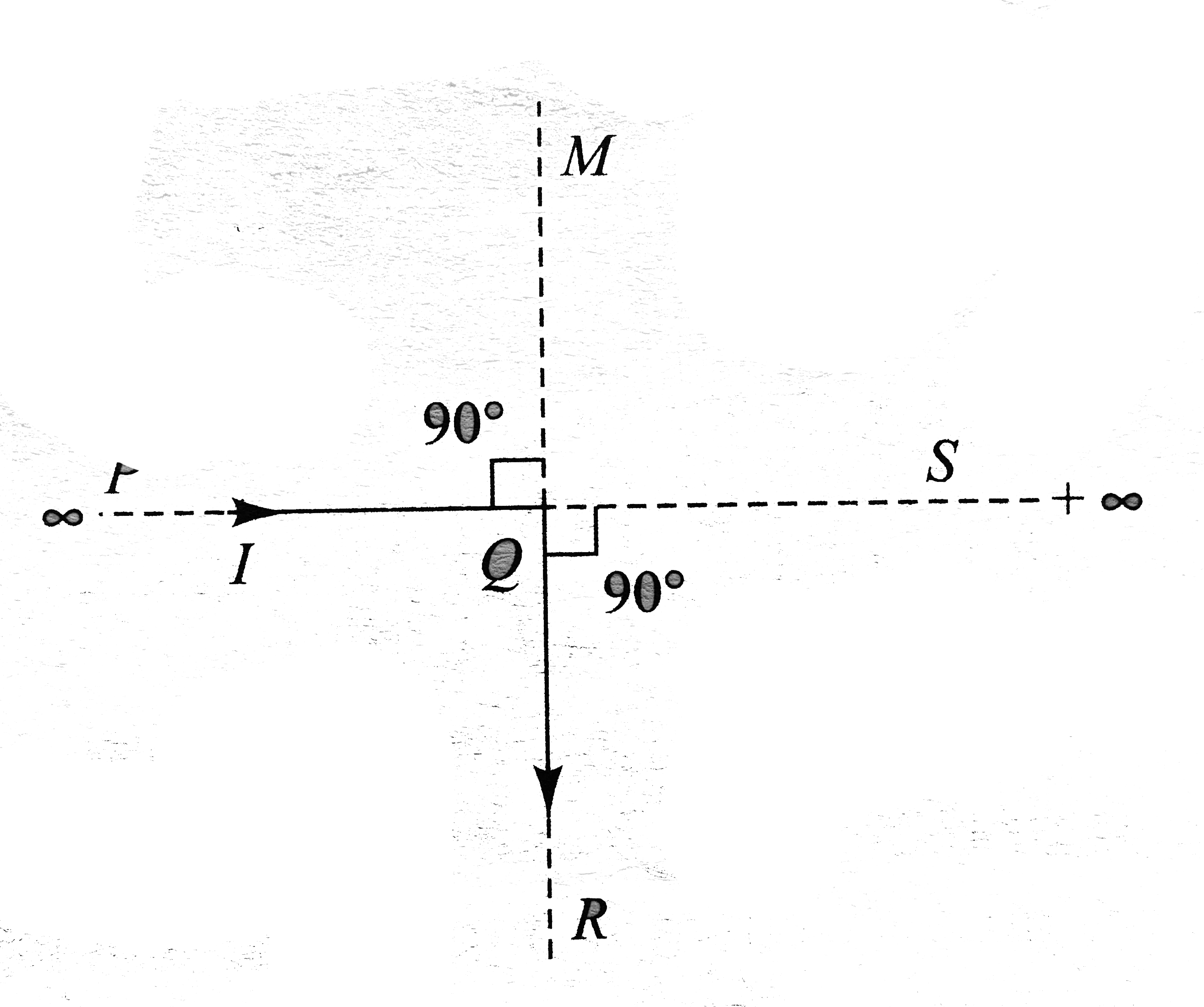
View SolutionAn infinetely long conductor PQR is bent tor form a right angle as shown in Fig. A current I flows through PQR. The magnetic field due to this current carrying conductor at the point M is `B_1`. Now, another infinitely long straight conductor QS, is connected at Q so that the current is `1/2I` in QR as well as in QS, is the current in PQ remaininig unchanged. The magnetic field at M is now `B_2`. The ratio `B_1//B_2` is given by
View SolutionTwo concentric coils each of radius equal to `2 pi cm` are placed at right angles to each other ` 3 ampere and 4 ampere` are the currents flowing in each coil respectively. The magnetic induction in `weber//m^(2)` at the centre of the coils will be
`( mu_(0) = 4 pi xx 10^(-7) Wb// A.m)`
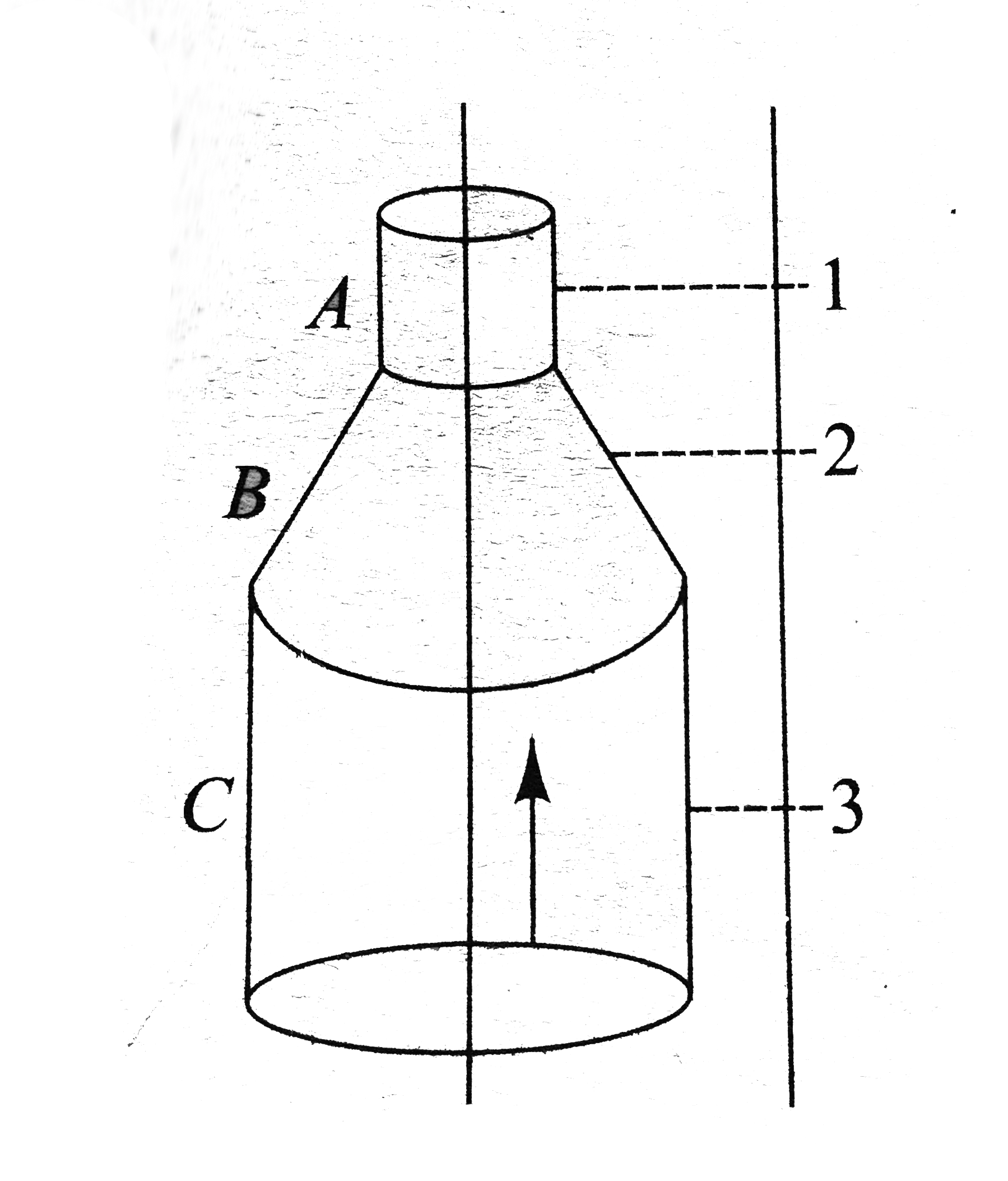
View SolutionA long, straight, hollow conductor (tube) carrying a current has two sections A and C of unequal cross sections joined by a conical section B. 1,2 and 3 are points on a line parallel to the axis of the conductor. The magnetic fields at 1,2 and 3 have magnitudes `B_1, B_2 and B_3`. Then,
View SolutionA coaxial cable consists of a thin inner conductor fixed along the axis of a hollow outer conductor. The two conductor carry equal currents in opposite directions. Let `B_1 and B_2` be the magnetic fields in the region between the conductors and outside the conductor, respectively. Then,
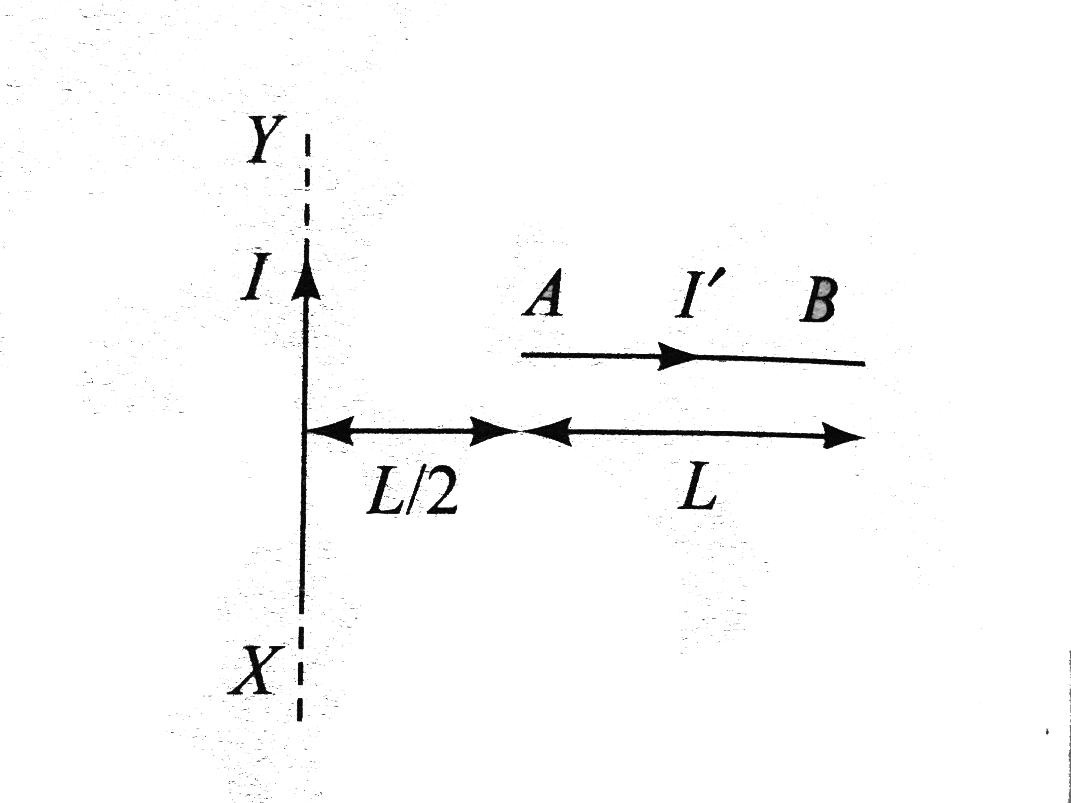
View SolutionA conductor AB of length L carrying a current I', is placed perpendicular to a long straight conductor XY carrying a current I as shown in Fig. The forces on AB has magnitude
View SolutionThe magnetic field at the centre of an equilateral triangular loop of side 2L and carrying a current i is
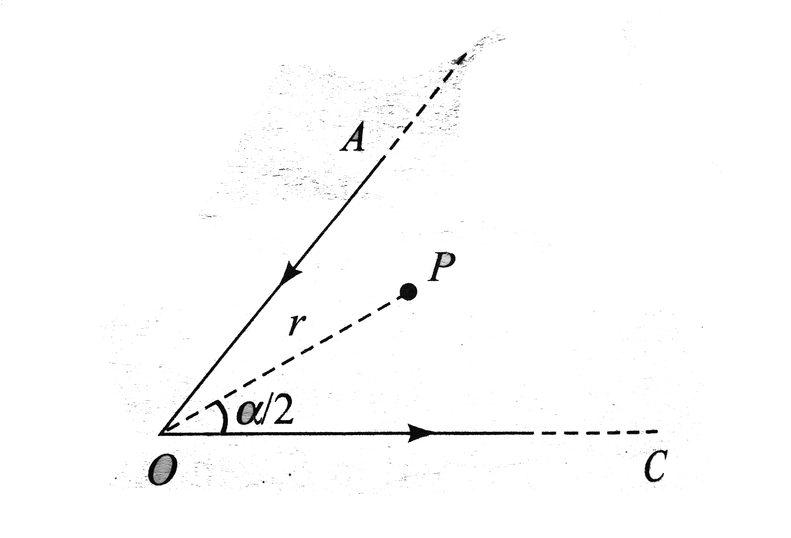
View SolutionTwo wires AO and OC carry equal currents i as shown in Fig. One end of both the wires extends to infinity. Angle AOC is `alpha`. The magnitude of magnetic field is point P on the bisector of these two wires at a distance r from point O is
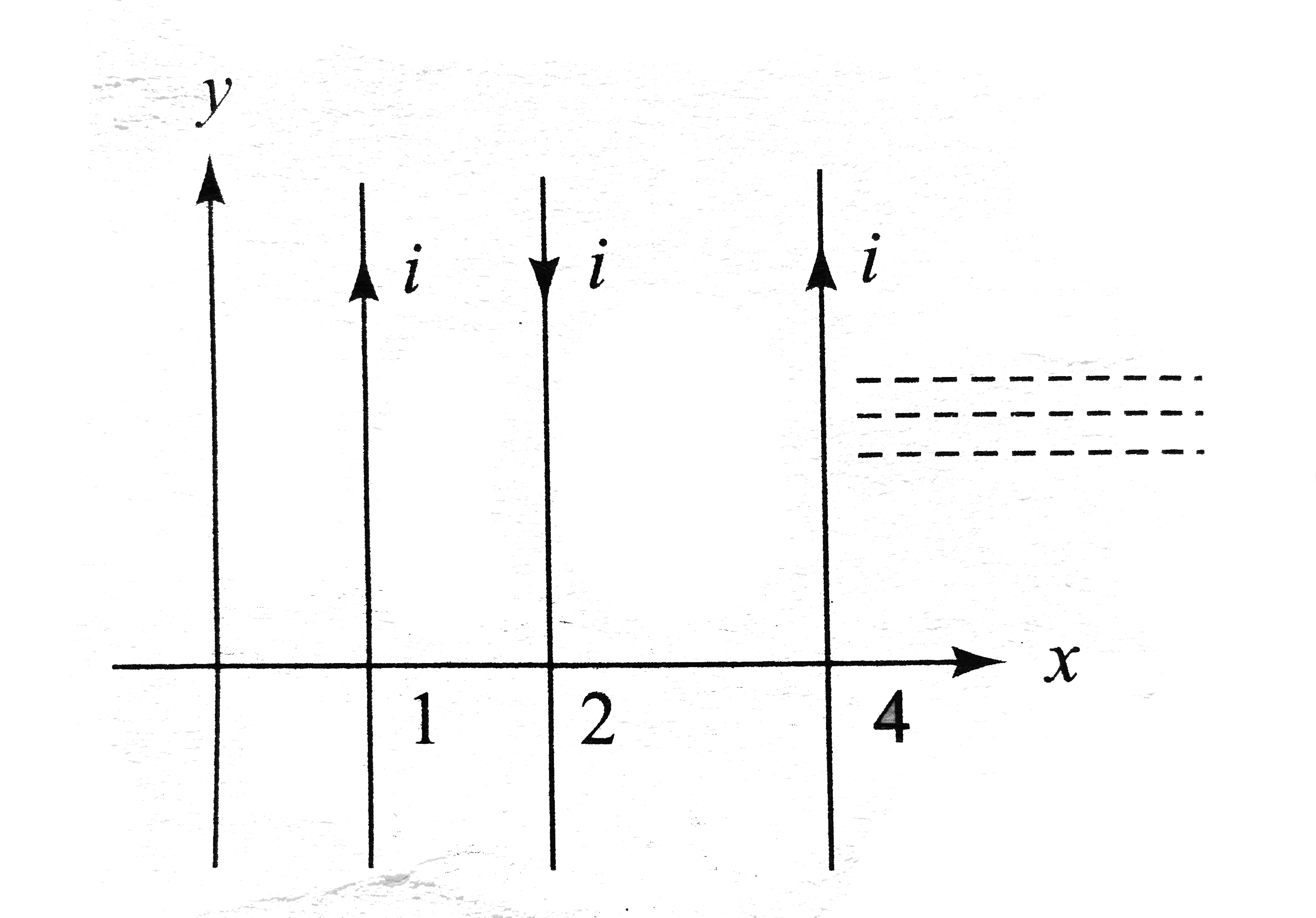
View SolutionEqual currents `i=1` A are flowing through the wires parallel to y-axis located at `x=+1m, x=+2m, x=+4m` and so on...., etc. but in opposite directions as shown in Fig The magnetic field (in tesla) at origin would be
View SolutionSame current i is flowing in the three infinitely long wires along positive x-,y- and z-directions. The magnetic filed at a point (0,0,-a) would be
View SolutionTwo very long straight parallel wires carry steady currents `i` and `2i` in opposite directions. The distance between the wires is `d`. At a certain instant of time a point charge `q` is at a point equidistant from the two wires in the plane of the wires. Its instantaneous velocity `vecv` is perpendicular to this plane. The magnitude of the force due to the magnetic field acting on t he charge at this instant is
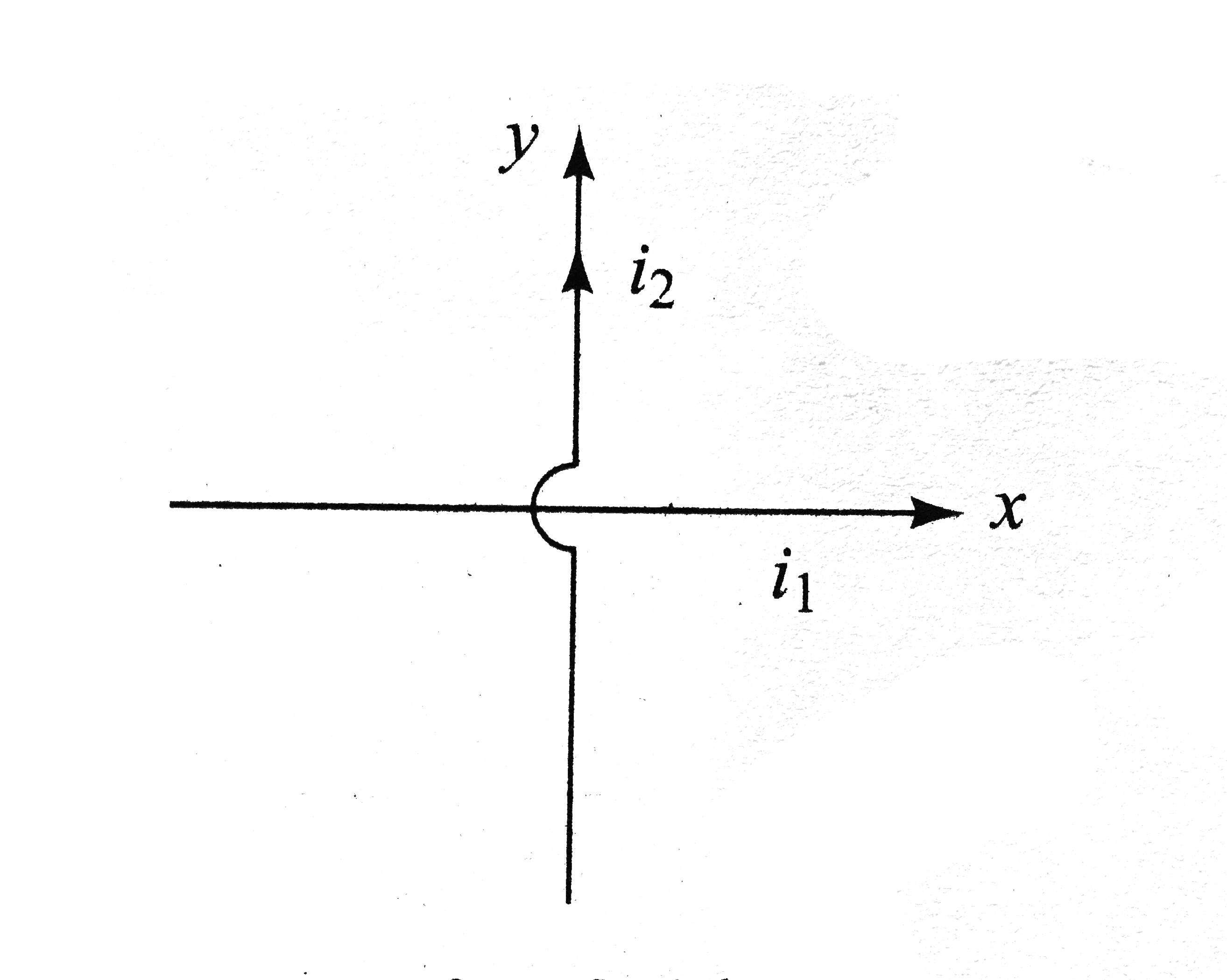
View Solutiontwo infinite wires, carrying currents `i_1 and i_2`., are lying along x-and y-axes, as shown in the x-y plane. Then,
View SolutionA long cylinder of wire of radius 'a' carries a current i distributed uniformly over its cross section. If the magnetic fields at distances `rlta and Rgta` from the axis have equal magnitude, then
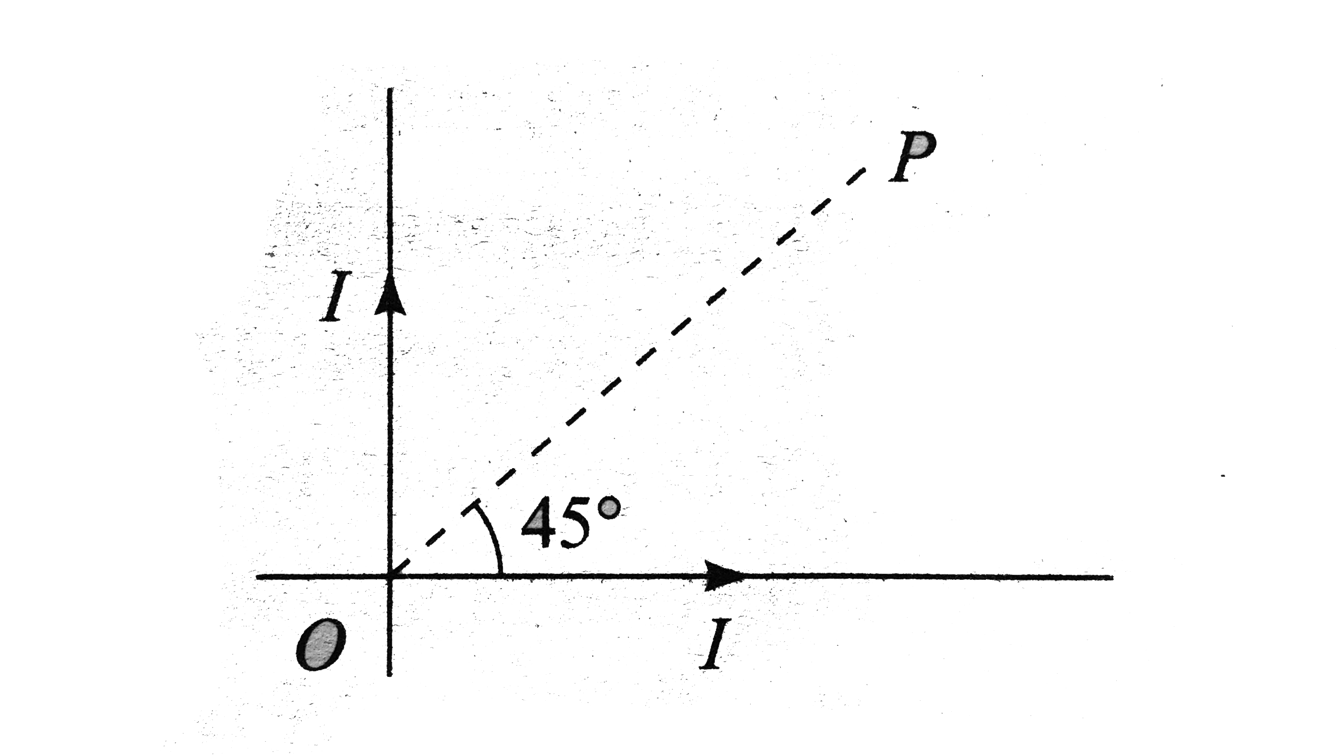
View SolutionTwo infinite long wires, each carrying current I, are lying along x- and y-axis, respectively. A charged particle, having a charge q and mass m, is projected with a velocity u along the straight line OP. The path of the particle is (neglect gravity)
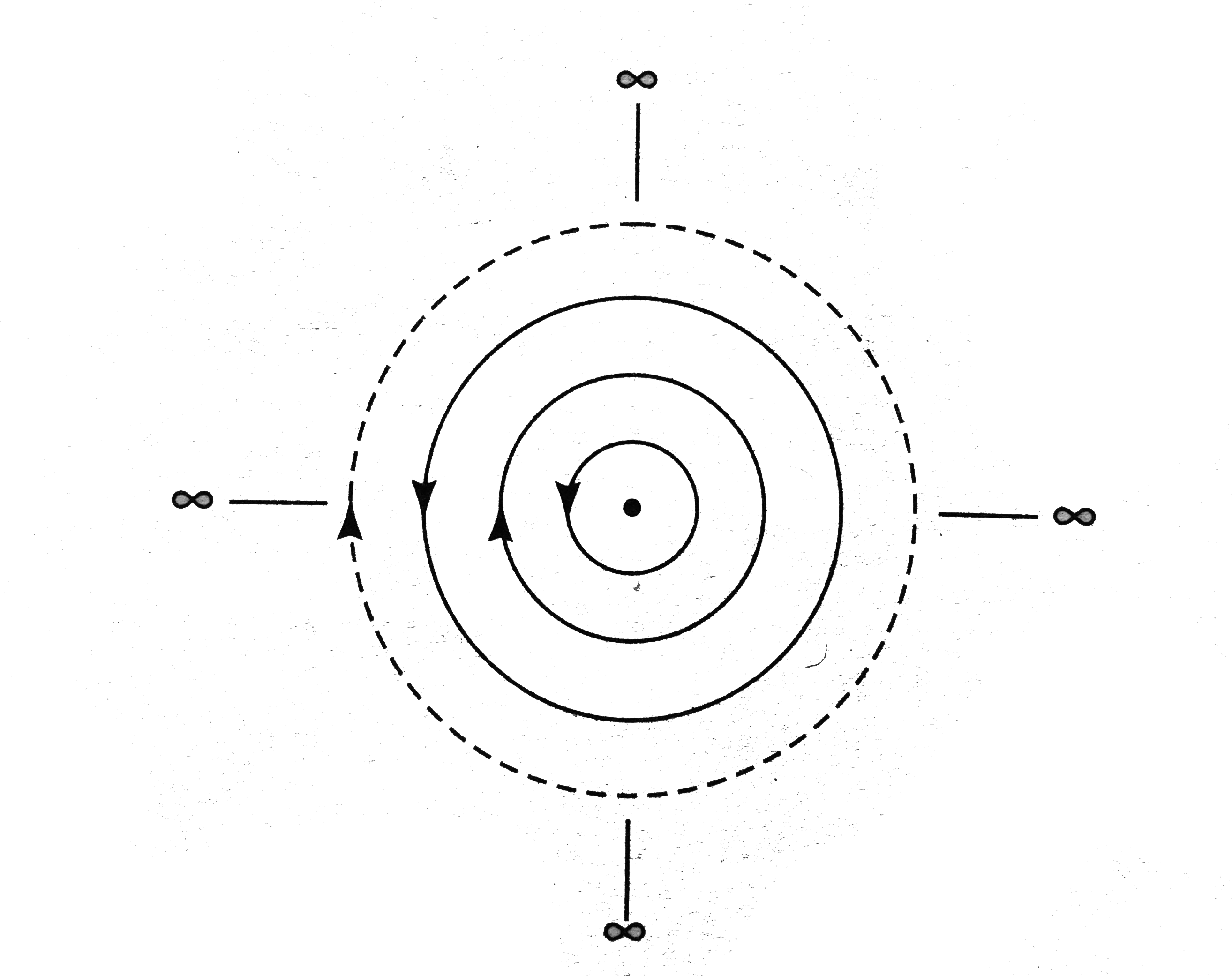
View SolutionIn Fig. infinite conducting rings each having current i in the direciton shown are placed concentrically in the same plane as shown in the figure. The radii of rings are `r,2r,2^2r,2^3r,......,(oo)`. The magnetic field at the centre of rings will be
View SolutionA very long straight conducting wire, lying along the z-axis, carries a current of 2A. The integral `ointvecB.dvecl` is computed along the straight line PQ, where P has the coordinates `(2cm,2cm,0)` and Q has the coordinates `(2cm, 2cm ,0)`. The integral has the magnitude (in SI units)`
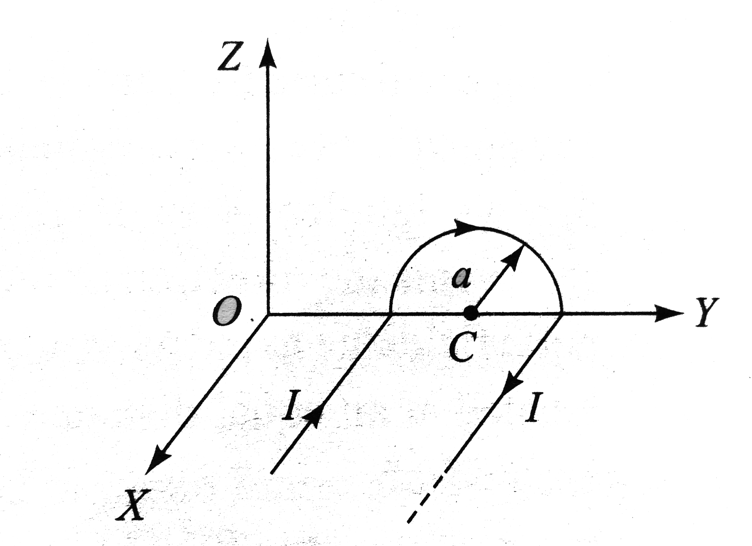
View SolutionA long wire bent as shown in fig. carries current I. If the radius of the semicircular portion is a, the magnetic field at centre C is
View SolutionAn infinitely long current carrying wire carries current i. A charge of mass m and charge q is projected with speed v parallel to the direction of current at a diatance r from it. Then, the radius of curvature at the point of projection is
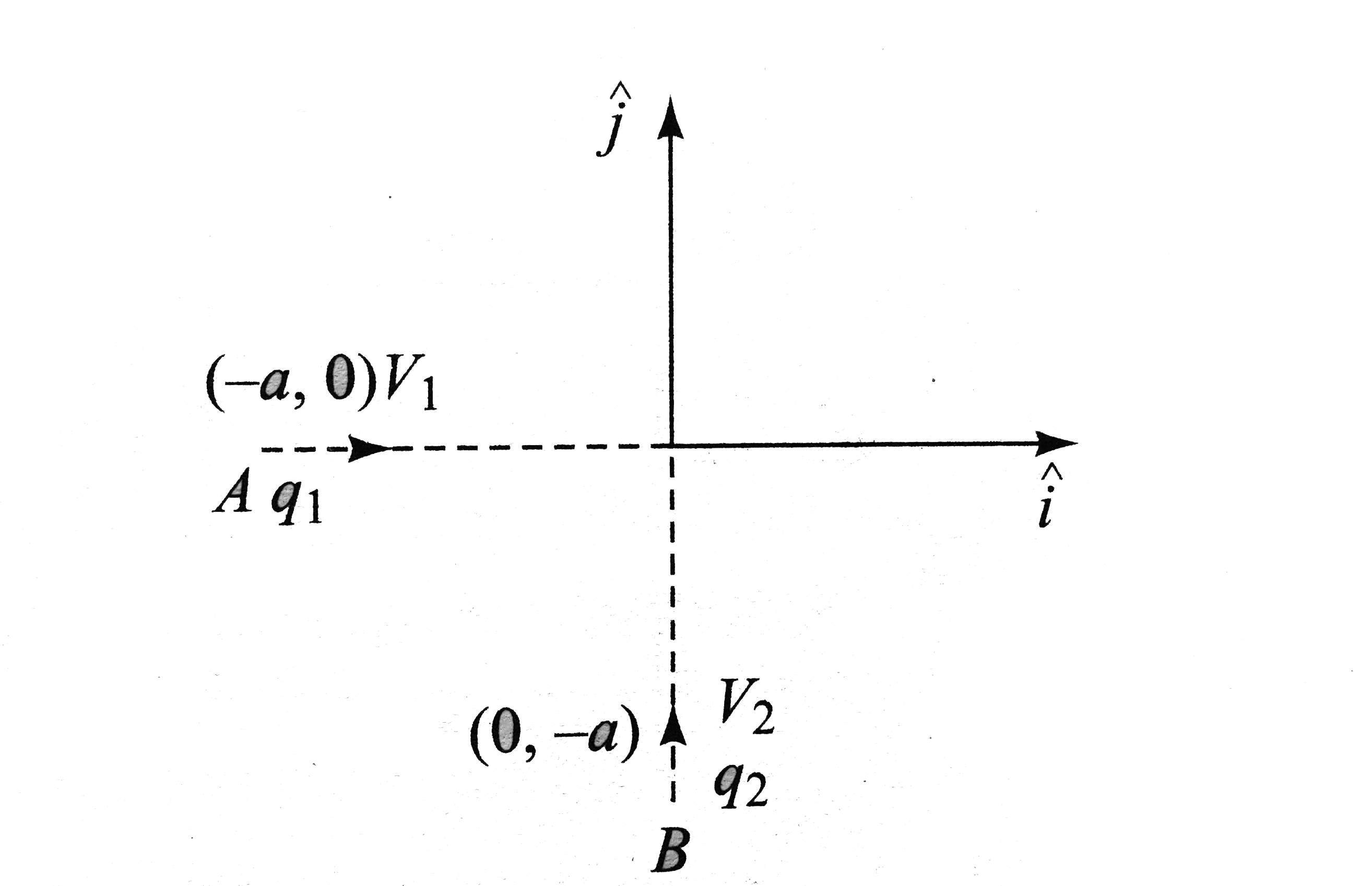
View SolutionTwo positive charges `q_1 and q_2` are moving with velocities `v_1 and v_2` when they are at points A and B, respectively, as shown in Fig. The magnetic force experienced by charge `q_1 ` due to the other charge `q_2` is
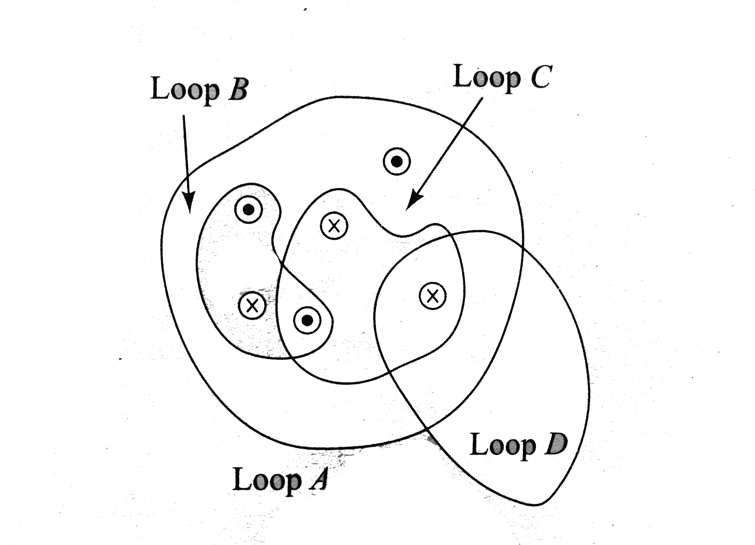
View SolutionConsider six wires coming into or out of the page, all with the same current. Rank the line integral of the magnetic field (from most positive to most negative) taken counterclockwise around each loop shown
View SolutionA positively charged disk is rotated clockwise as shown in Fig. The direction of hte magnetic field at a point A in the plane of the disk is
View SolutionFigure. Shows two long wires carrying equal currents `I_1 and I_2` flowing in opposite directions. Which of the arrows labeled A to D correctely represents the direction of the magnetic field due to the wires at a point located at an equal distance d from each wire?
View SolutionIn the figures given show four different sets of wires that cross each other without actually touching. The magnitude of the current is the same in all four cases and the directions of current flow are as indicated. For which configuration will the magnetic field at the centre of the square formed by the wires be equal to zero?
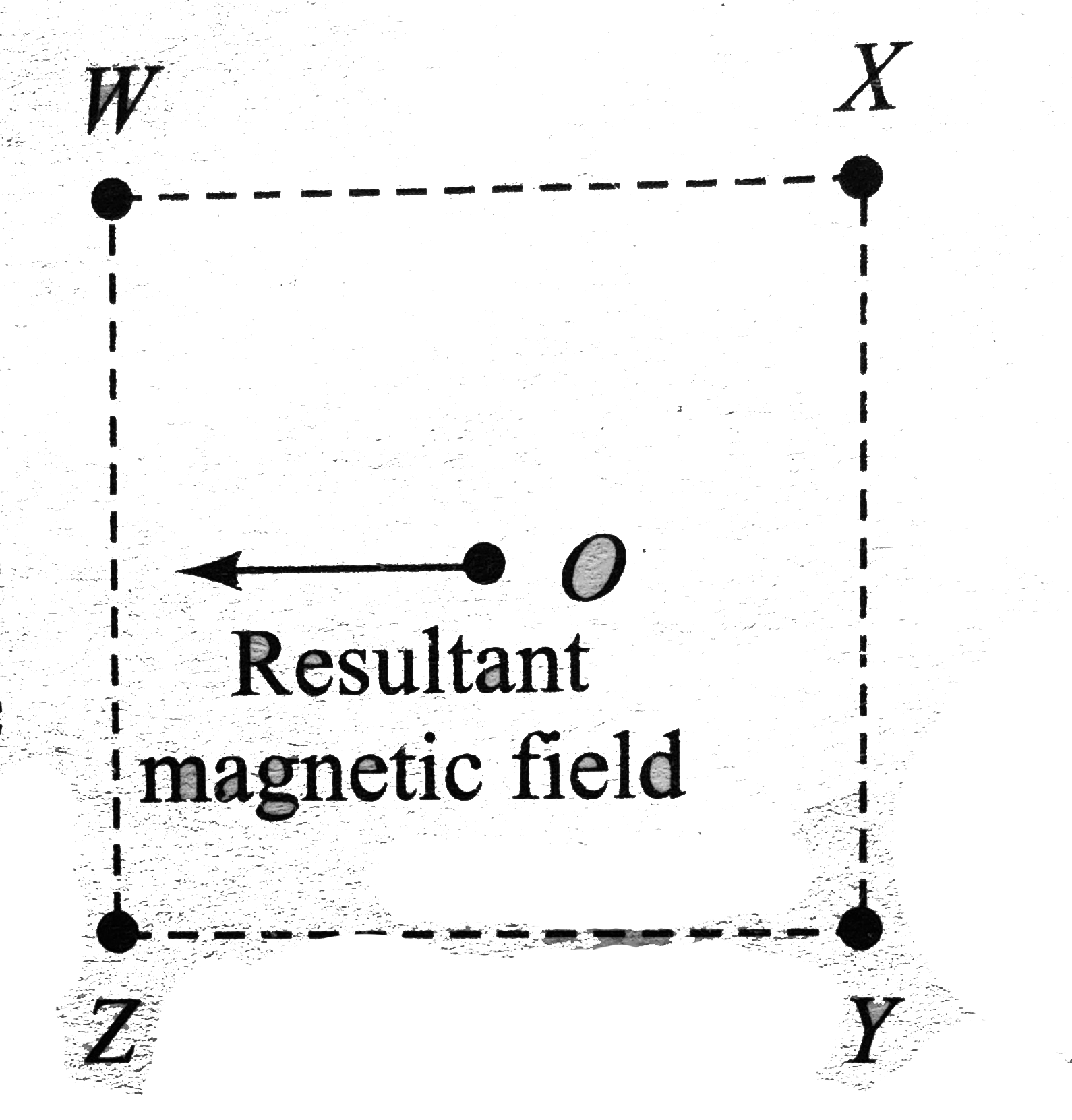
View SolutionFour parallel conductors, carrying equal currents, pass vertically through the four corners of a square WXYZ. In two conductors, the current is flowing into the page, and in the other two out into the page, and in the other two out of the page. In what directions must the currents flow to produce a resultant magnetic field in the direction shown at O, the centre of the square?
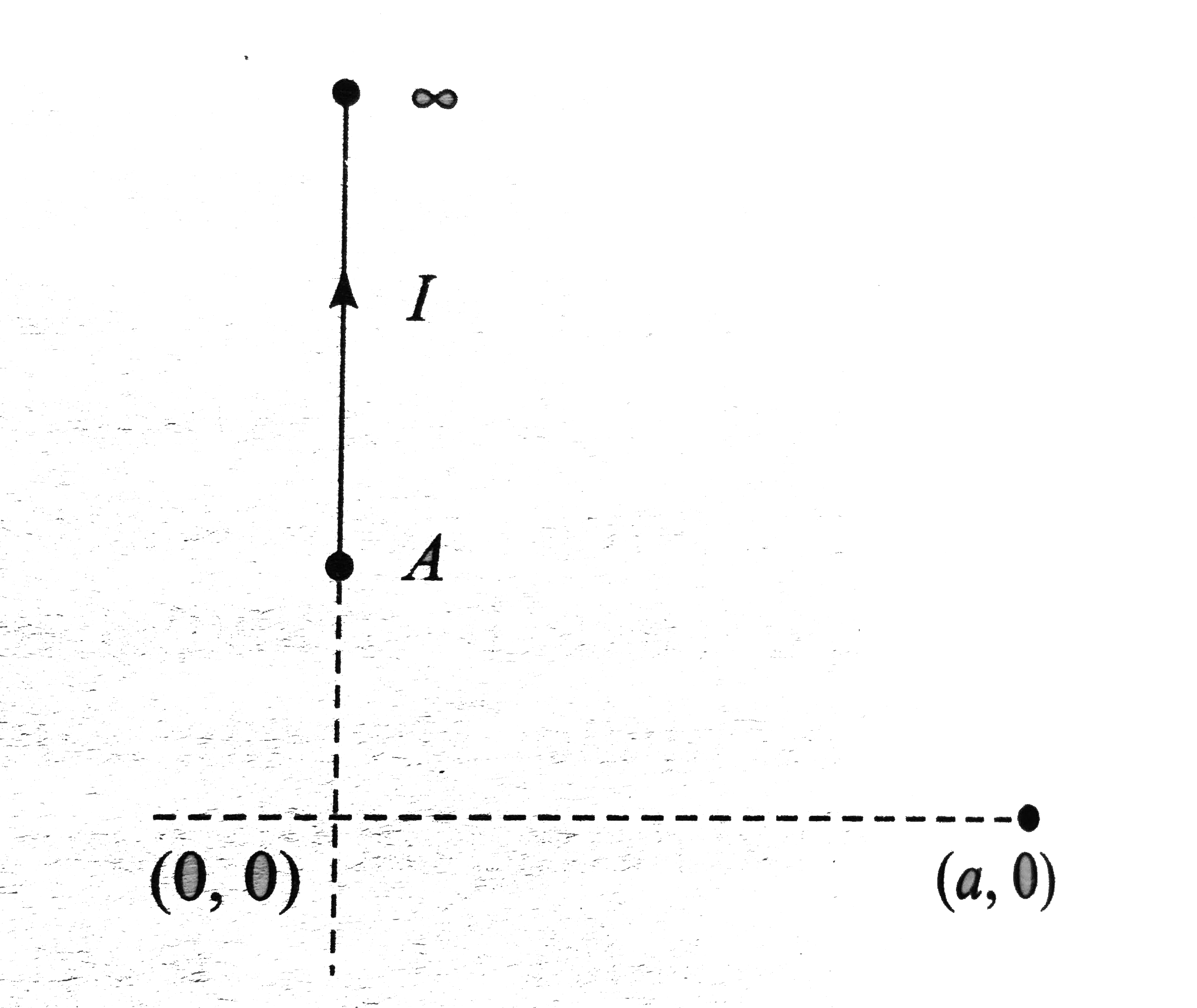
View SolutionAn infinitely long wire carrying current I is along Y-axis such taht its one end is at point A(0,b) while the wire extends upto `+oo`. The magnitude of magnetic field strength at point (a,0) is
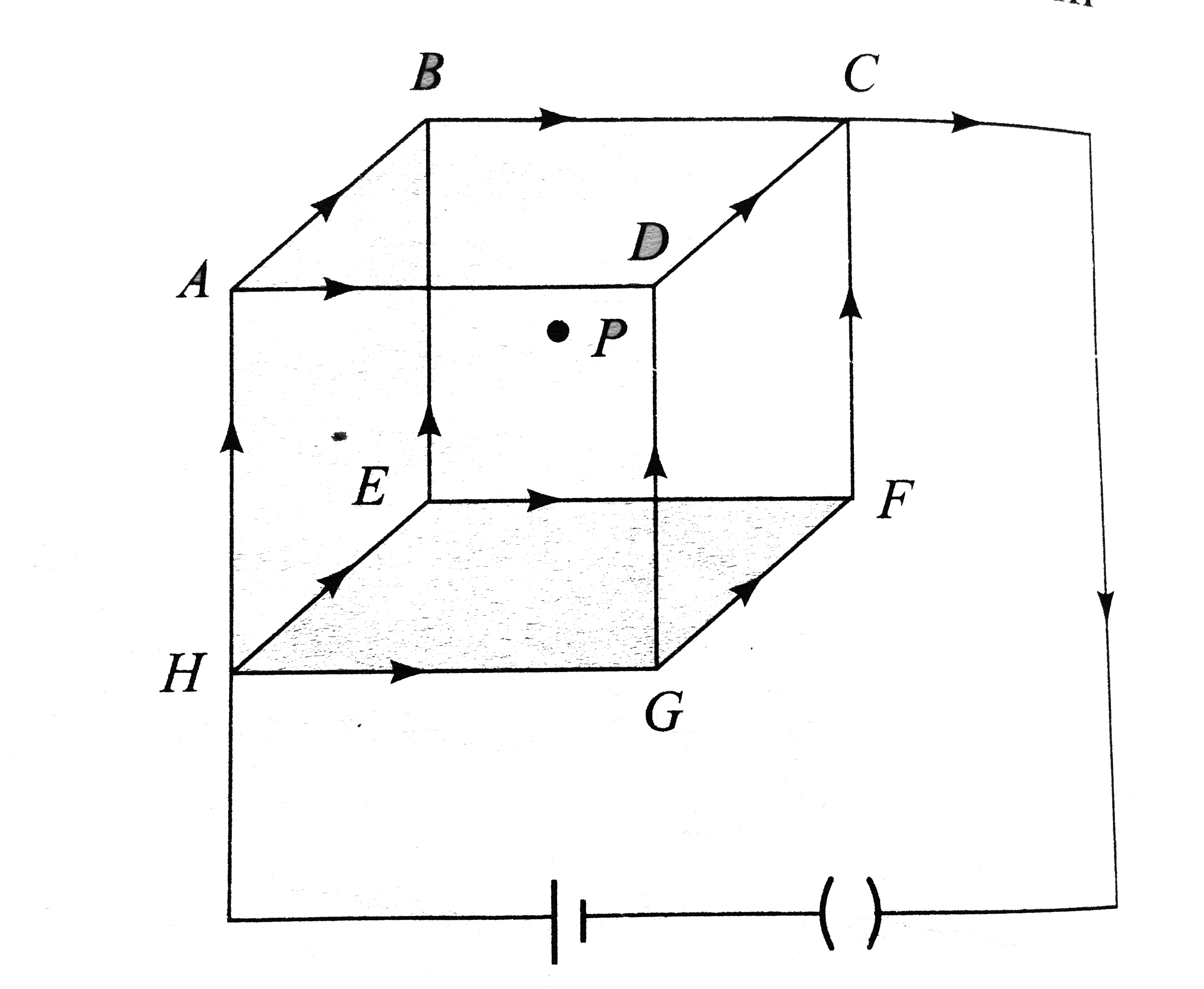
View SolutionA steady current is set up in a cubic network composed of wires of equal resistance and length d as shown in Fig. What is the magnetic field at centre P due to the cubic network?
View SolutionA point charge is moving in clockwise direction in a circle with constant speed. Consider the magnetic field produced by the charge at a fiexed point P (not at the centre of circle ) on the axis of the circle. Then,
View SolutionAn `alpha` is moving along a circle of radius R with a constant angular velocity `omega`. Point A lies in the same plane at a distance 2R from the centre. Point A records magnetic field produced by the `alpha`-particle. If the minimum time interval between two successive time at which A records zero magnetic field is t, the angular speed `omega`, in terms of t, is
View SolutionThree infinite current carrying conductors are placed as shown in Fig. Two wires carry same current while current in third wire is unknown. The three wires are electrically insulated from each other and all of them are in the plane of paper. Which of the following is correct about point P which is also in the same plane?
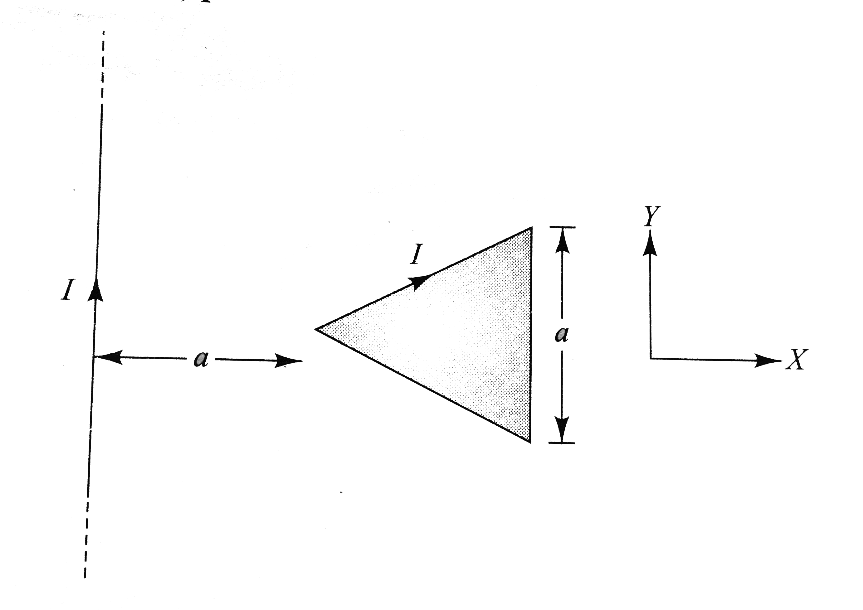
View SolutionAn equilateral triangular loop is kept near to a current carrying long wire as shown fig. under the action of magnetic force alone, the loop
View SolutionA particle is moving with velocity `vecv=hati+3hatj` and it produces an electric field at a point given by `vecE=2hatk`. It will produce magnetic field at that point equal to (all quantities are in SI units)
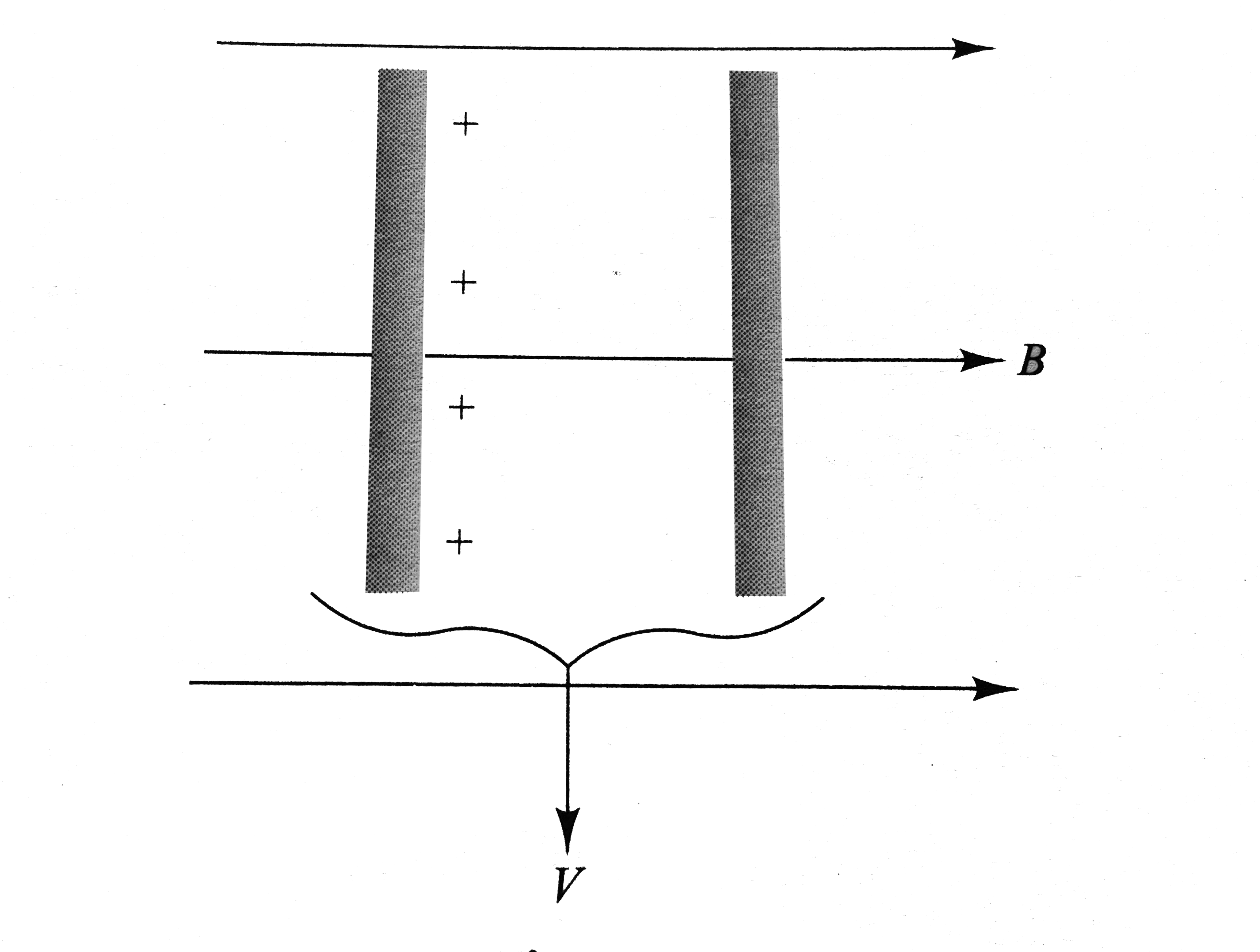
View SolutionA parallel plate capacitor is moving with a velocity of `25 ms^-1` through a uniform magnetic field of 4.0T as shown in Fig. If the electric field within the capacitor plates is `175NC^-1` and the plate area is `25xx10^-7m^2`, then the magnetic force experienced by the positive charge plate is
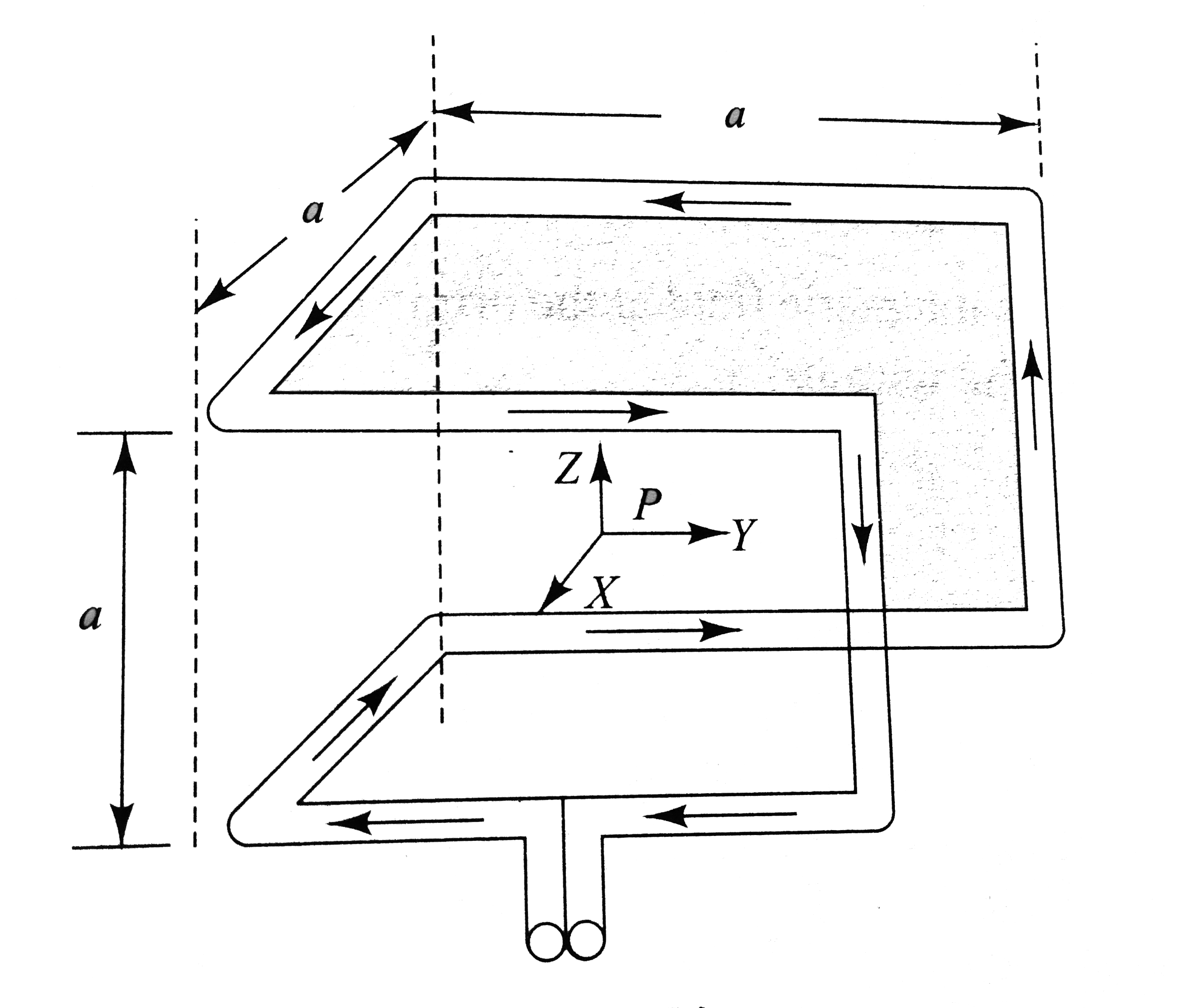
View SolutionCurrent I flows around the wire frame along the edge of a cube as shown in Fig. Point P is the centre of the cube. The incoming and outgoing wires have orientation toward P. Then,
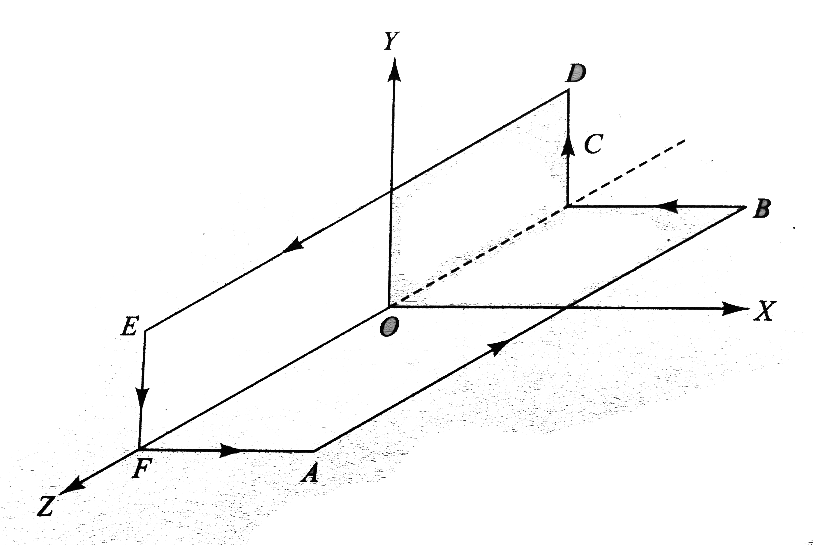
View SolutionIn Fig ABCDEFA was a square loop of side l, but is folded in two equal parts so that half of it lies in the x-z plane and the other half lies in the y-z plane. The origin O is centre of the frame also. The loop carries current 'i'. The magnetic field at the centre is
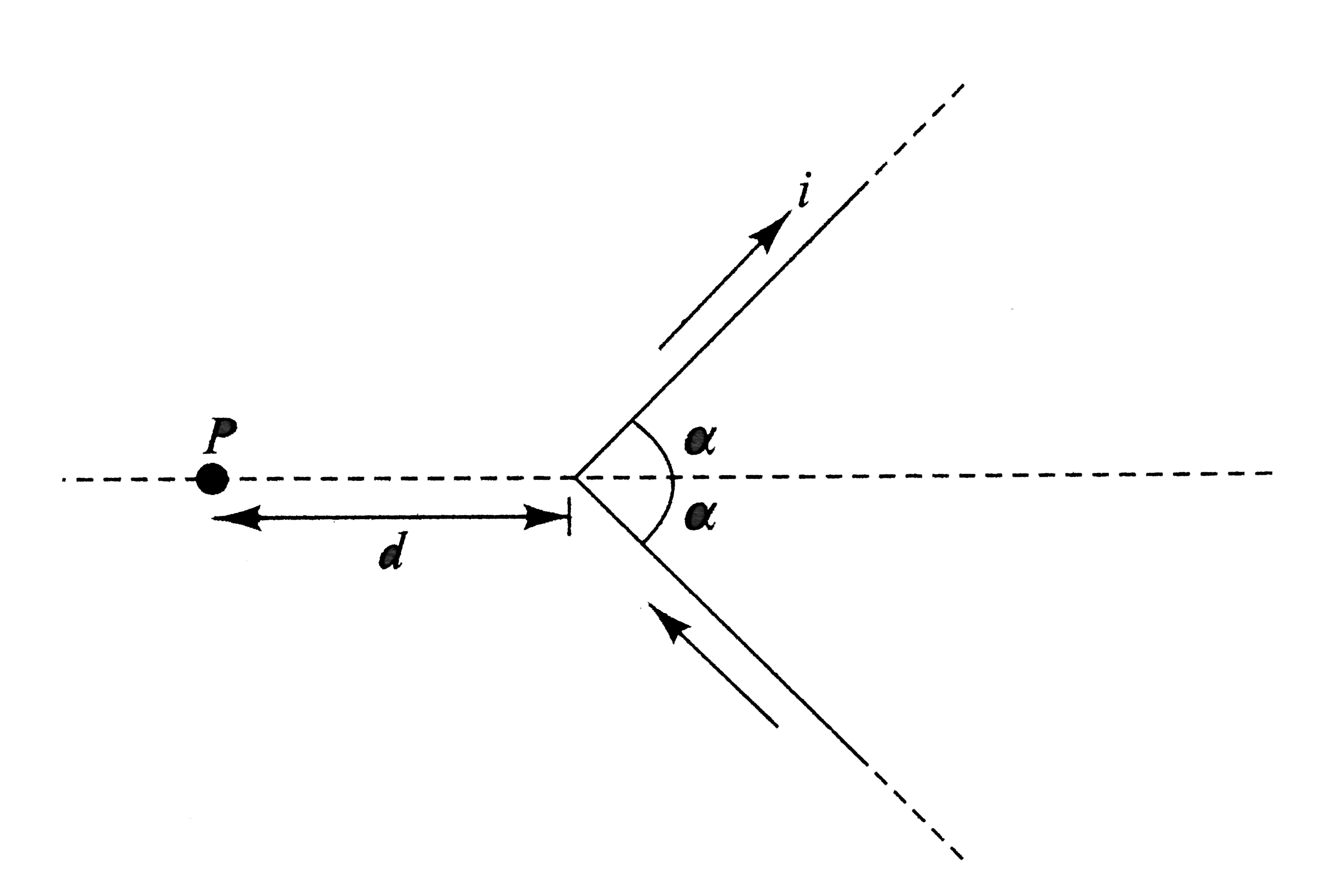
View SolutionIf the magnetic field at P can be written as `K tan (alpha/2)`,
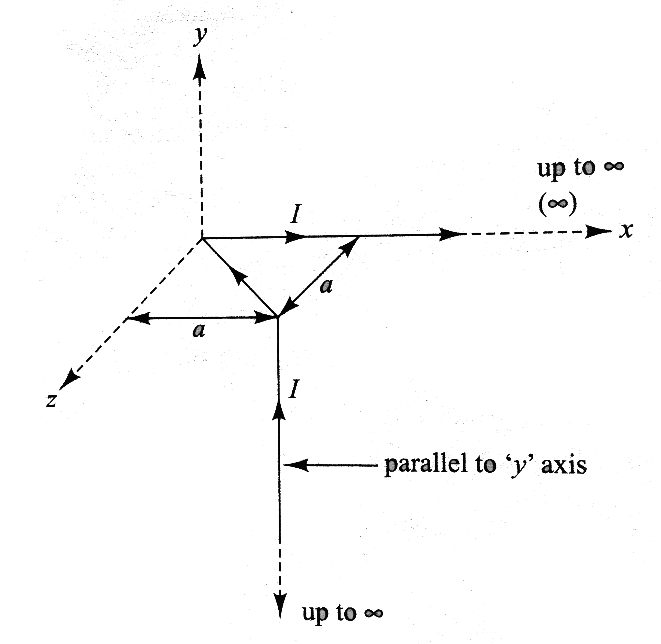
View SolutionThe magnetic field at the origin due to the current flowing in the wire is
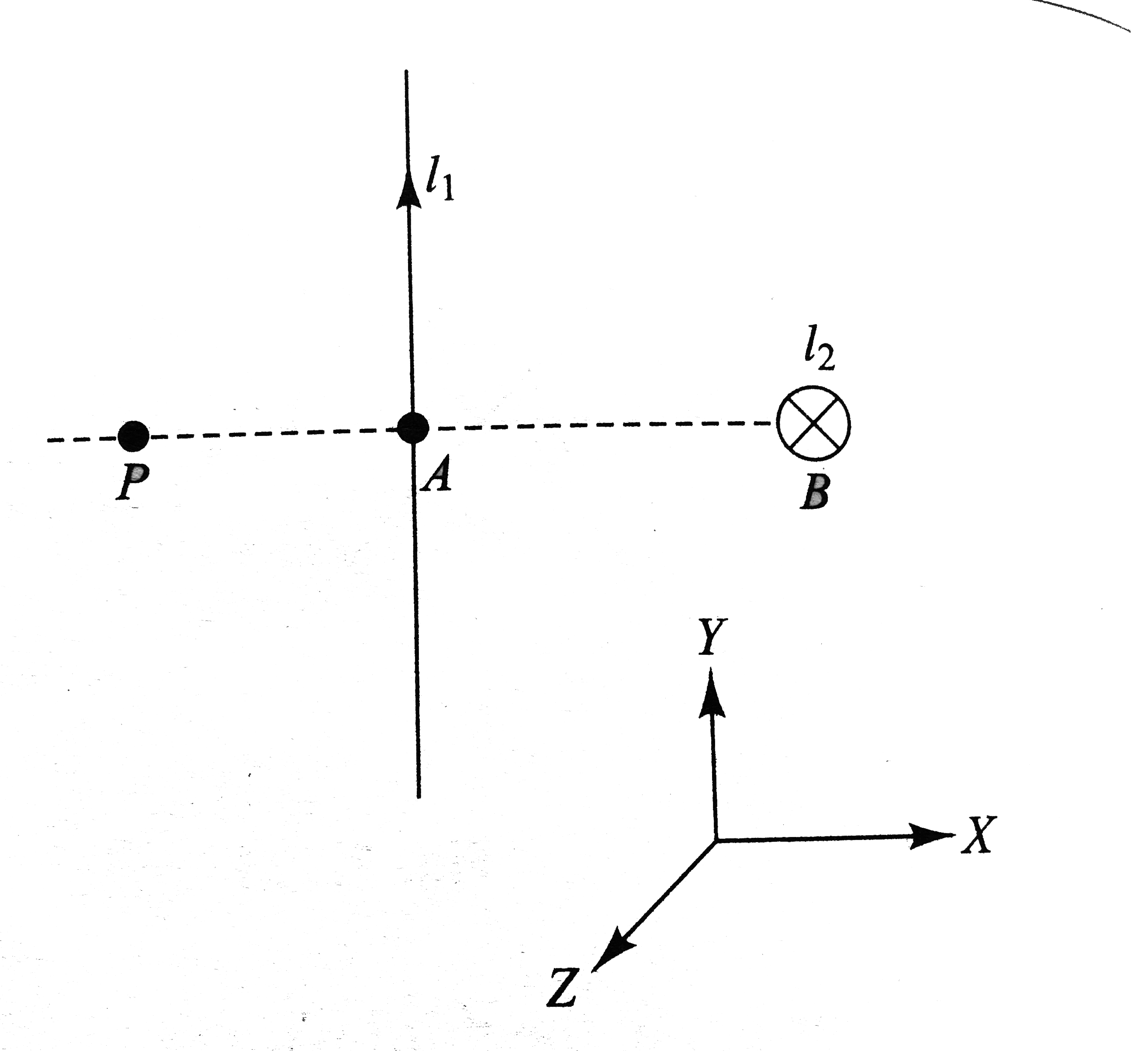
View SolutionTwo infinitely long linear conductors are arranged perpendicular to each other and are in mutually perpendicular planes as shown in Fig. If `I_1=2A` along the y-axis, `I_2=3A`, along -ve z-axis and AP=AB=1cm, the value of magnetic field strength `vecB` at P is
View SolutionFigure shows an Amperian path ABCDA. Part ABC is in vertical plane PSTU while part CDA is in horizontal plane PQRS. Direction of circulation along the path is shown by an arrow near point B and at D. `ointvecB.dvecl` for this path according to Ampere's law will be
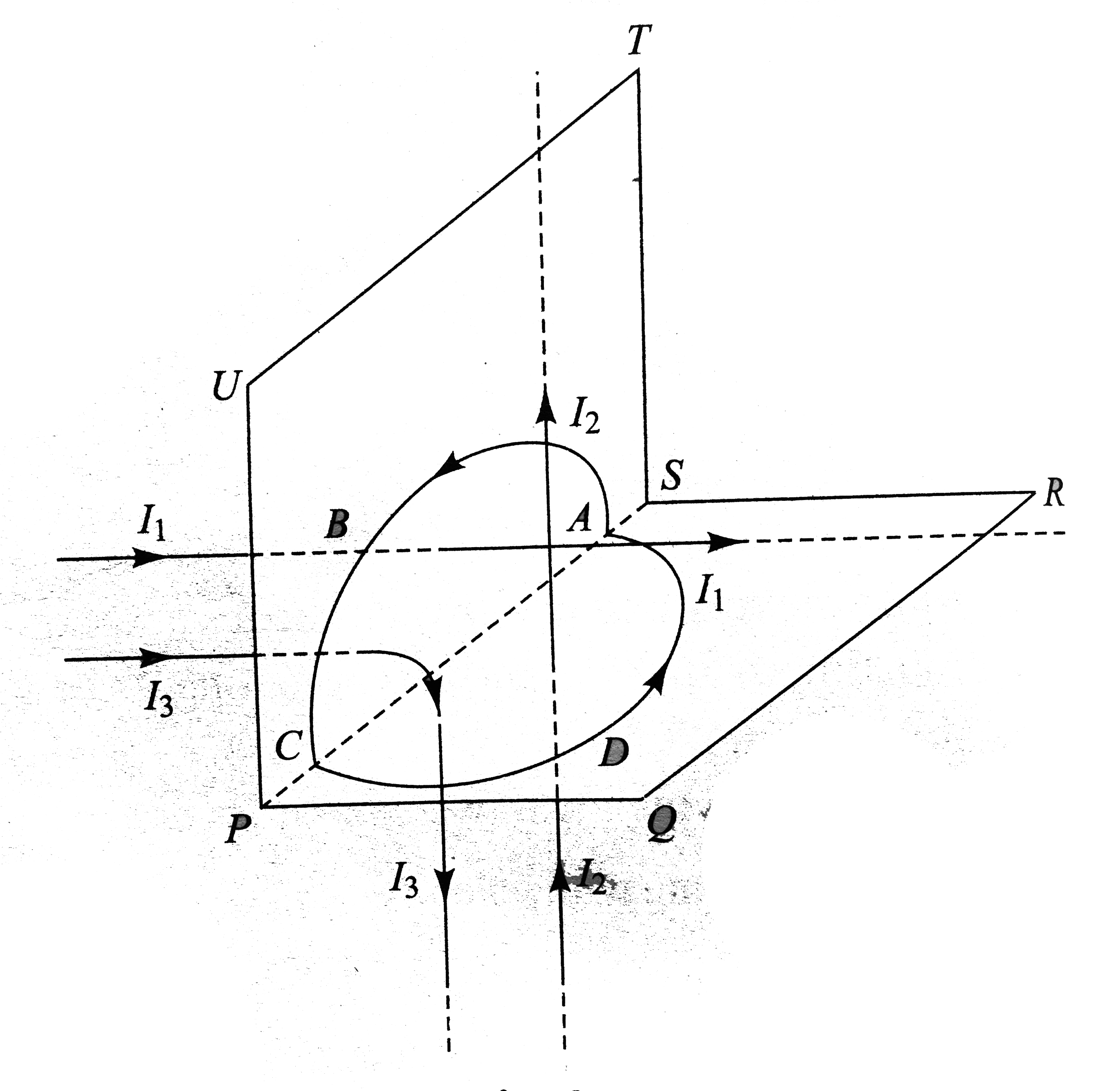
View SolutionA coaxial cable made up of two conductors. The inner conductor is solid and is of radius `R_1` and the outer conductor is hollow of inner radius `R_2` and outer radius `R_3`. The space between the conductors is filled with air. The inner and outer conductors are carrying currents of equal magnitudes and in opposite directions. Then the variation of magnetic field with distance from the axis is best plotted as
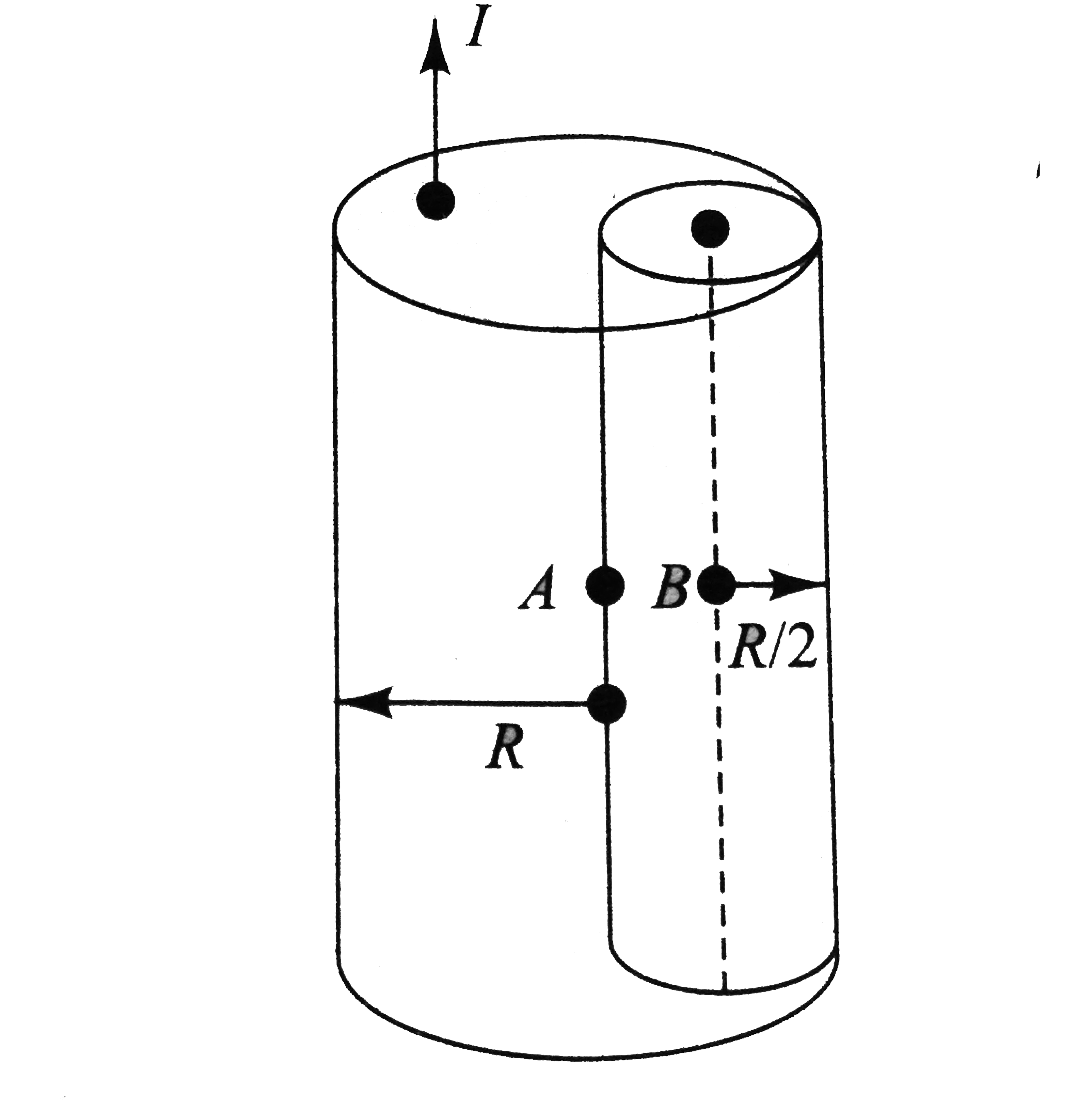
View SolutionFrom a cylinder of radius R, a cylider of radius `R//2` is removed, as shown in Fig. Current flowing in the remaining cylinder is I. Then, magnetic field strength is
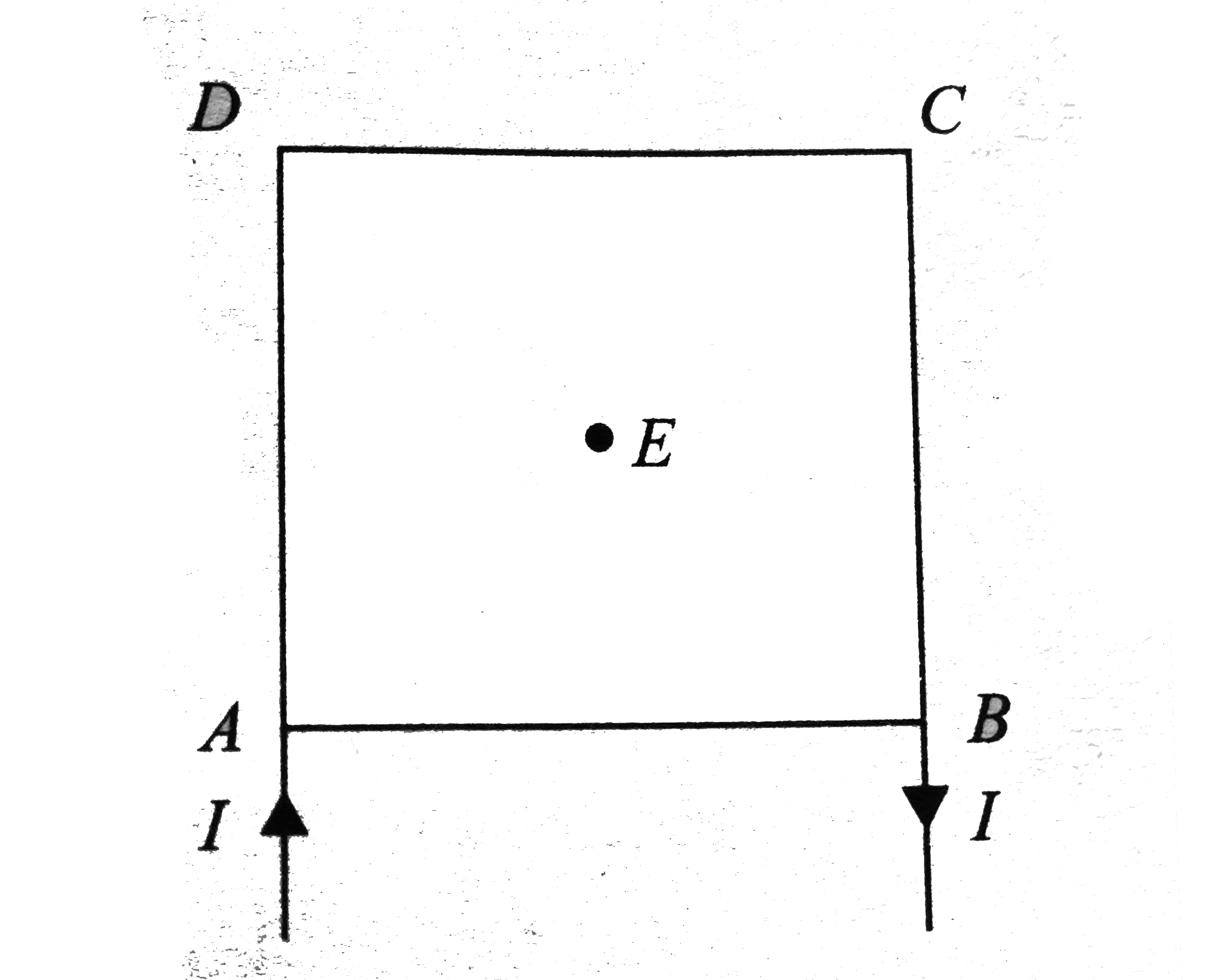
View SolutionCurrent I enters at A in a square loop of uniform resistance and leaves at B. The ratio of magnetic field at E, the centre of square, due to segment AB to that due to DC is
View SolutionA wire of length l is used to form a coil. The magnetic field at its centre for a give current in it is minimum if the coil has
View SolutionThe value of the electric field strength in vacuum if the energy density is same as that due to a magnetic field of induction 1T in vacuum is
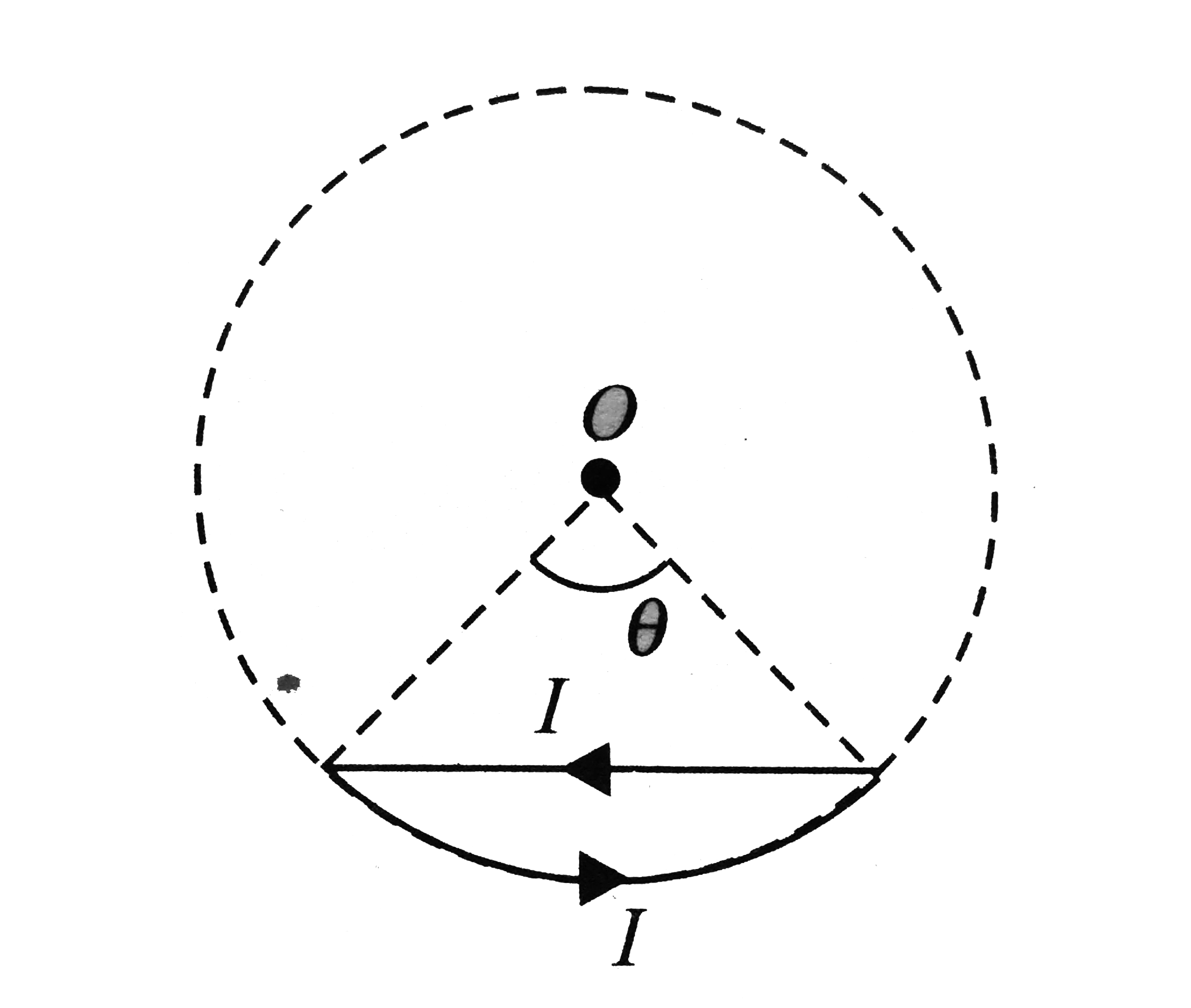
View SolutionFigure. Shows a small loop carrying a current I. The curved portion is an arc of a circle of radius R and the straight portion is a chord to the same circle subtending an angle `theta`. The magnetic induction at centor O is
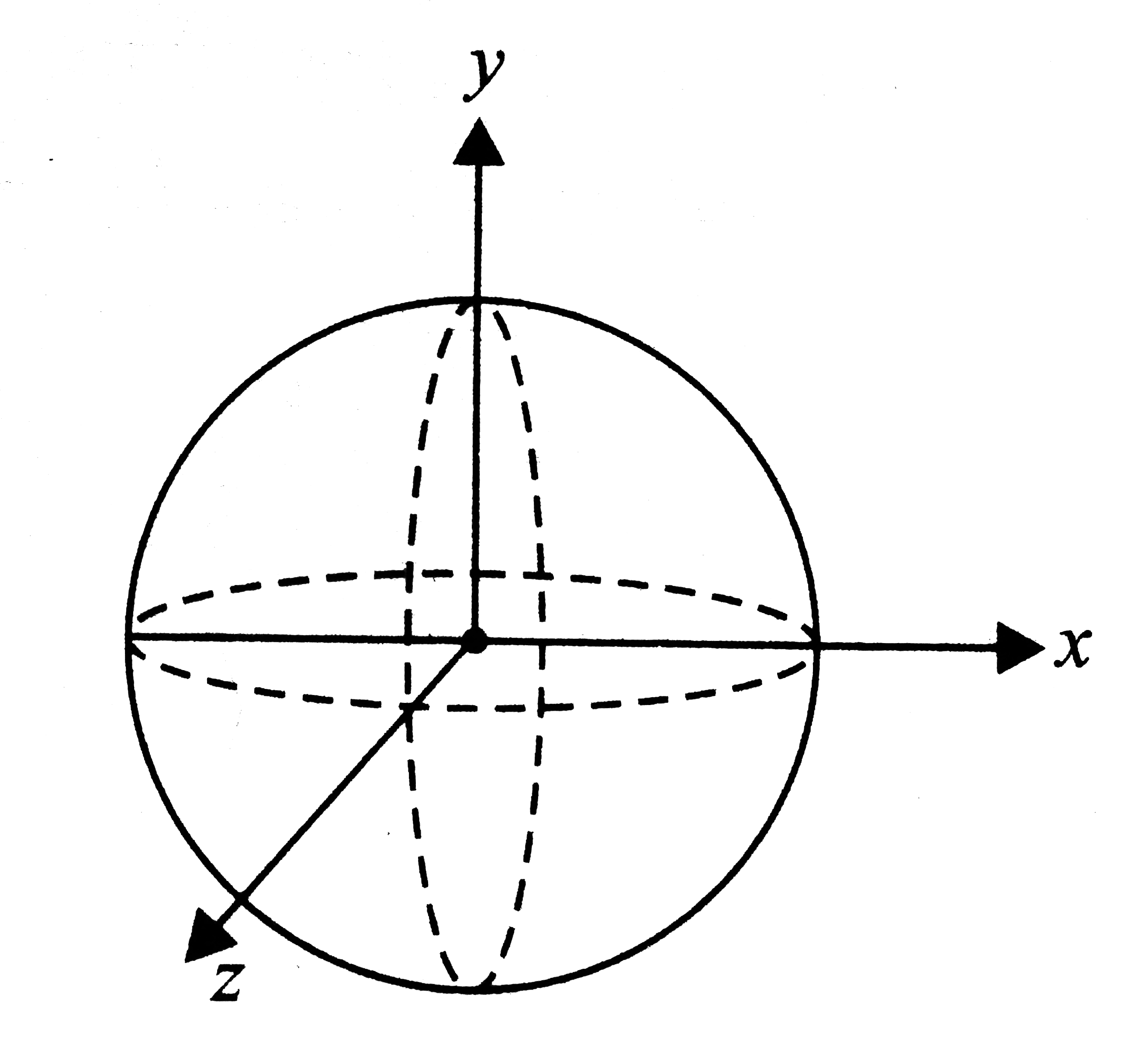
View SolutionThree rings, each having equal radius R, are placed mutually perpendicular to each other and each having its centre at the origin of coordinate system. If current I is flowing through each ring, then the magnitude of the magnetic field at the common centre is
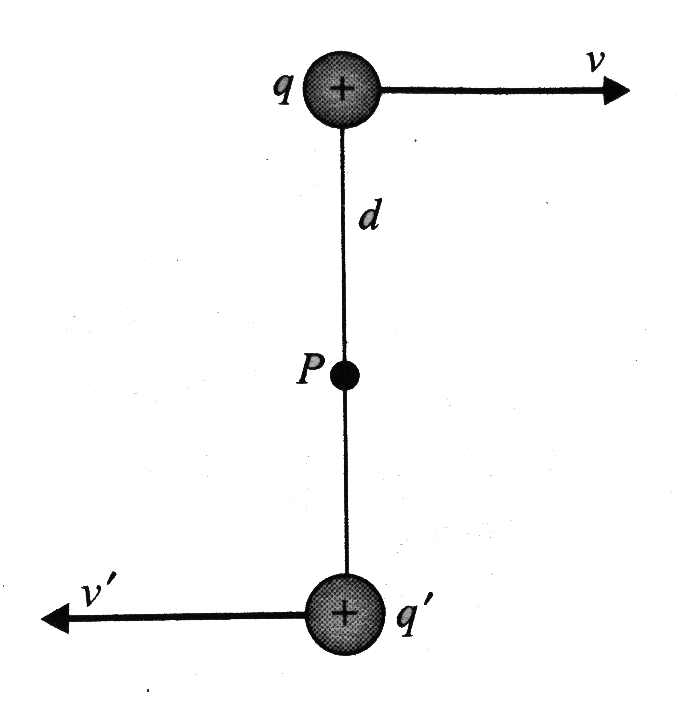
View SolutionPositive point charge `q=+8.00muC and q'=+3.00muC` are moving relative to an observer in Fig. The distance d is 0.120m. When the two charges are at the locations shown in the figure, what are the magnitude and direction of the net magnetic field they produce at point P? `(Take v=4.50xx10^6ms^-1 and v'=9.00xx10^6ms^1)`
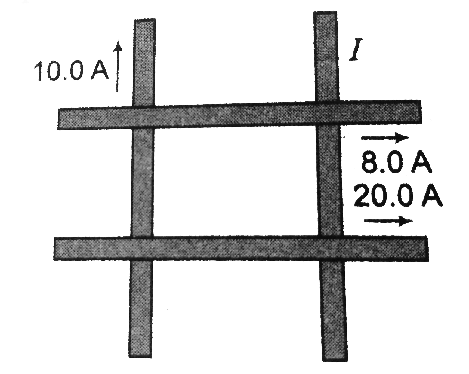
View SolutionFour very long, current carrying wires in the same plane intersect to form a square `40.0 cm` on each side as shown in figure. Find the magnitude and direction of the current `I` so that the magnetic field at the centre of square is zero. Wires are insulated from each other.
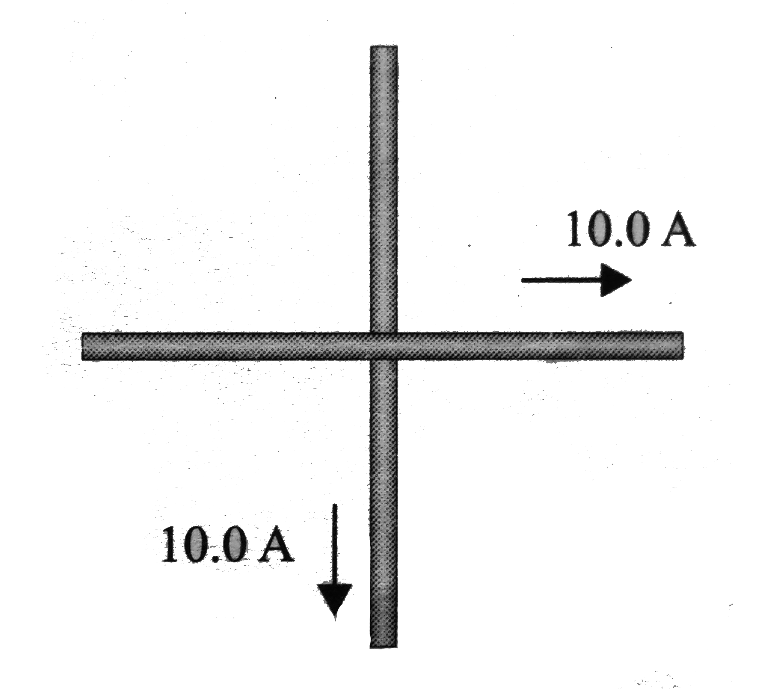
View SolutionTwo very long, straight wires carrying, currents as shown in Fig. Find all locations where the net magnetic field is zero.
View Solution
Exercise (single Correct ) questions and complete solutions for chapter SOURCES OF MAGNETIC FIELD of CENGAGE PHYSICS (HINGLISH) of Class 12
All Exercises from CENGAGE PHYSICS Class 12 PHYSICS SOURCES OF MAGNETIC FIELD
- Archives (fill In The Blanks)
- Archives (integer)
- Archives (linked Comprehension)
- Archives (multiple Correct )
- Archives (single Correct Anser)
- Concept Exercise 2.1
- Concept Exercise 2.2
- Exercise (assertion-reasioning )
- Exercise (integer)
- Exercise (linked Comprehension)
- Exercise (multiple Currect )
- Exercise (single Correct )
- Exercise (subjective )
- Illustration
- single correct Ansewer type
- single correct Answer Type
- Solved Example
- Subjective type