Complete Solutions to Exercise of chapter CAPACITORS of Class 12 book with complete answers and questions
| Class 12 | PHYSICS |
| Chapter | CAPACITORS |
| DC PANDEY | Exercise |
| Number Of Questions | 100 |
| Academic Year | 2023-24 |
Find the dimensions of capacitance.
View SolutionNo charge will flow when two conductors having the same charge are connected to each other. this statement true or false?
View SolutionTwo conductors of capacitance `1muF` and `2muF` are charged to `+10V` and `-20 V` They are now connected by a conducting wire. Find
(a) their common potential
(b) the final charges on them
(c) the loss of energy during, redistribution of charges.
View SolutionA capacitor has a capacitance of `7.28 muF`. What amount of charge must be placed on each of its plates to make the potential difference between its plates equAl to `25.0 V`?
View SolutionA parallel air capacitance `245muF` has a charge of magnitude `0.48muC` on each plate. The plates are `0.328 mm` apart.
(a) What is the potential difference between the plates?
(b) What is the area of each plate?
(c) What is the surface charge density on each plate?
View SolutionTwo parallel plates have equal and opposite charges. When the space between the plates is evacuted, the electric field is `E_0=3.20xx10^5V//m`. When the space is filled with electric the electric field is `E-2.50xx10^5V//m`
a. What is the dielectric constant?
b. What is the charge density on each surface of the dielectric?
View SolutionFind charges on different capacitors.
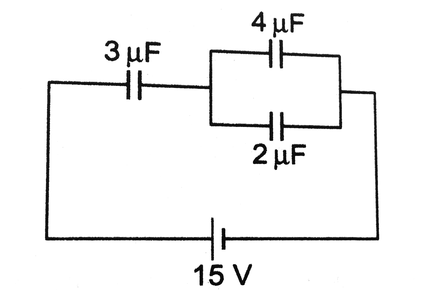
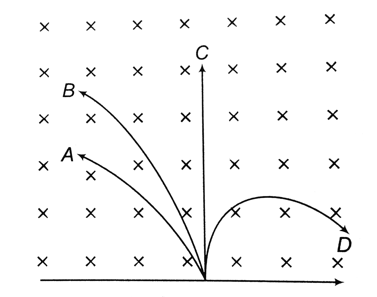
View SolutionFind the charges on different capacitors.
View SolutionAssertion : From the relation `C = q/V` We can say that, if more charge `q` is given to a conductor, its capacitance should increase.
Reason : Ratio `q/V` will remain constant for a given conductor.
View SolutionAssertion : A parallel plate capacitor is first charged and then distance between the plates is increased. In this process, electric field between the plates remains the same, while potential difference gets decreased.
Reason: `E=q/(Aepsilon_0)` and `V=q/(Adepsilon_0)` Since `q`, remain same, `E` will remain same while V will decrease.
View SolutionAssertion : When an uncharged capacitor is charged by a battery only `50%` of the energy supplied is stored in the capacitor.
Reason : Rest `50%` is lost.
View SolutionAssertion: Discharging graphs of two C.R. circuits having the same value of C is shown in figure. From the graph we can say that `tau_(C_1)gttau_(C_2)`
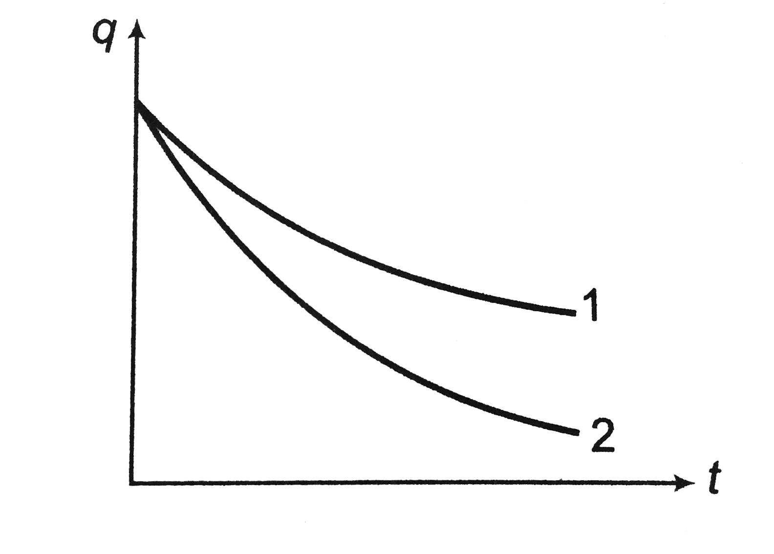
Reason: `R_1gtR_2`
View SolutionAssertion : In series combination, charges on two capacitors are always equal.
Reason : If charges are same, the total potential difference applied across two capacitors will be distributed in inverse ratio of capacities.
View SolutionAssertion : Two capacitors are charged from the same battery nd then connected as shown. A current will flow i ntil clock direction as soon as switch is closed.
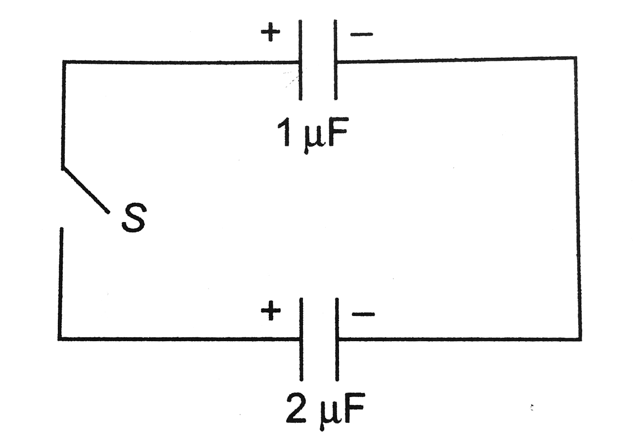
Reason: In steady state charges on two capacitors are in the ratio 1:2.
View SolutionAssertion: In the circuit shown in figure no charge will stored in the capacitor.
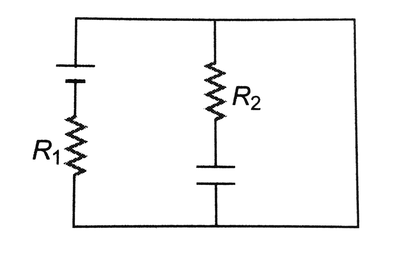
Reason: Current through `R_2` will be zero.
View SolutionAssertion: In the circuit in figure, time constant of charging of capacitor is s`(CR)/2`
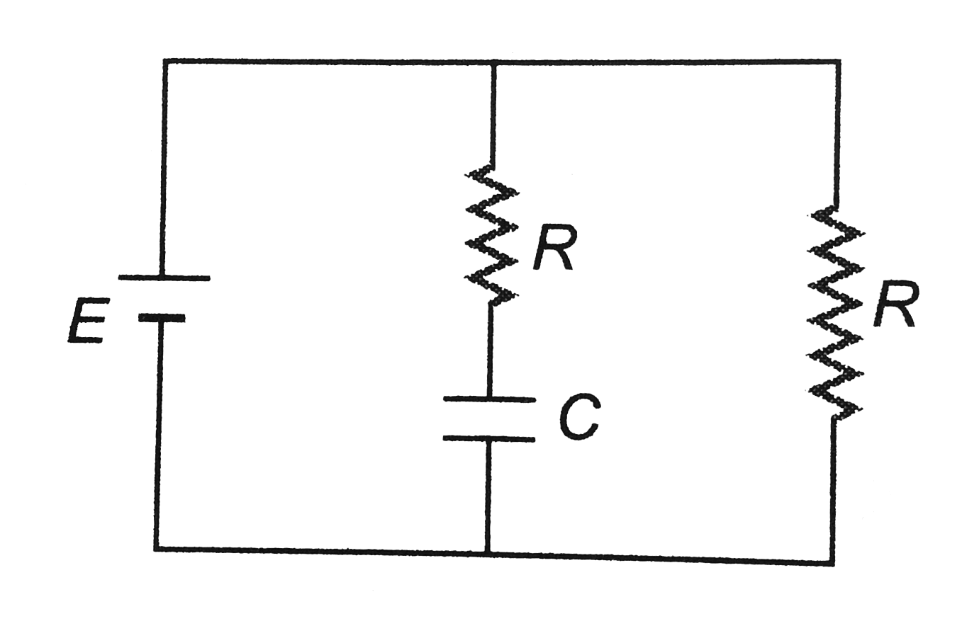
Reason: In the absence of capcitor in the circuit, two resistors are in parallel with the battery.
View SolutionAssertion: Two capacitors are connected in series with a battery. Energy stored across then is in inverse ratio of their capacity.
Reason: `U=1/2qV` or `UpropqV`
View SolutionAssertion: In the circuit shown in figure with a dielectric slab is inserted in `C_2`, the potential difference across `C_2` will decrease.
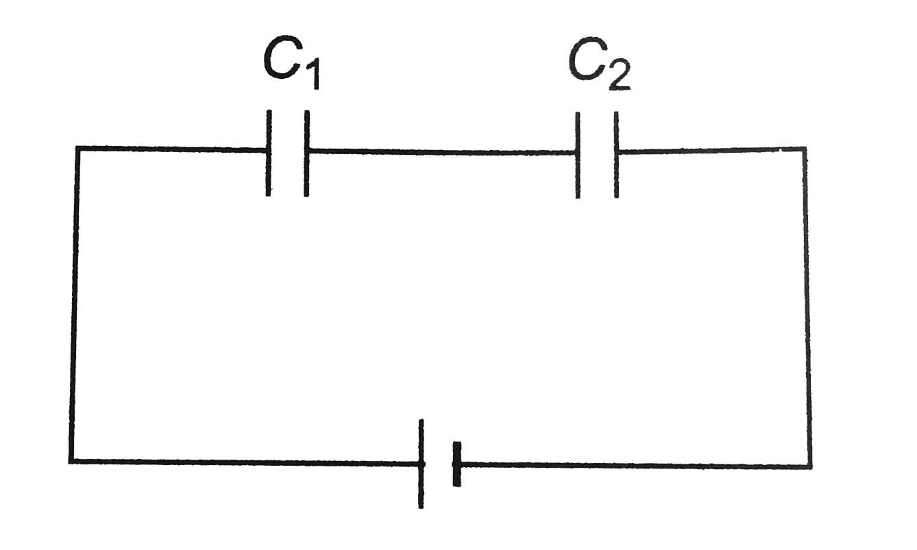
Reason: By inserting the slab a current will flow in the circuit in clockwise direction.
View SolutionThe separation between the plates of a charged parallel-plate capacitor is increased. The force between the plates
View SolutionIf the plates of a capacitor are joined together by as conducting wire, then its capacitance
View SolutionTwo metal spheres of radii `a` and `b` are connected by a thin wire. Their separation is very large compared to their dimensions. The capacitance of this system is
View Solution`n` identical capacitors are connected in parallel to a potential difference `V`. These capacitors are then reconnected in sereis, their charges being left undisturbed. The potential difference obtained is
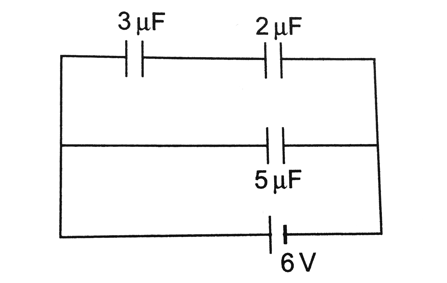
View SolutionIn the circuit shown in figure, the ratio of charge on `5muF` and `2muF` capacitor is
 `
`
View SolutionIn Millikan's oil drop experiment an oil drop of radius `r` and change `Q` is held in equilibrium between the plates of a charged parallel plate capacitor when the potential change is `V`. To keep a drop radius `2r` and with a change `2Q` is equilibriu between the plates the potential difference `V'` required is:
View SolutionTwo large parallel sheets charged uniformly with surfasce charge density `sigma` and `-sigma` are located as shown in the figure. Which one of the following graphs shows the variation of electric field along a line perpendicular to the sheets as one moves from `A` to `B` ?
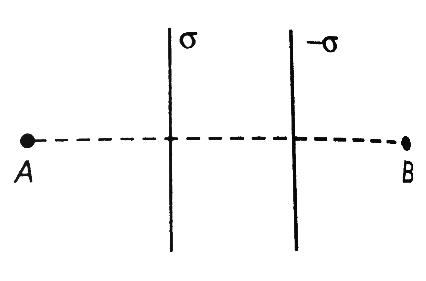 `
`
View SolutionWhen the switch is closed, the initial current through the `1Omega` resistor is
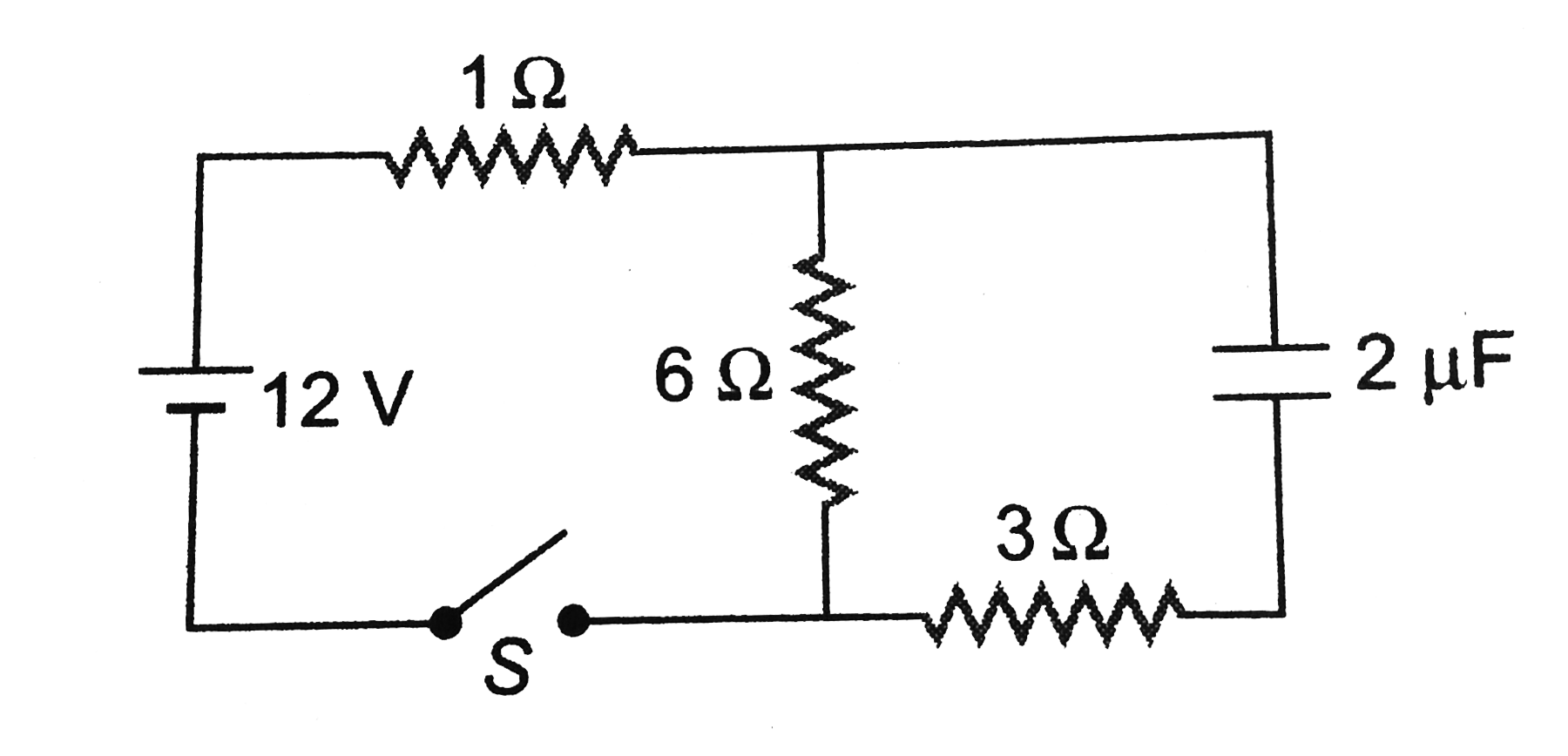 `
`
View SolutionA capacitor of capacitance `C` carrying charge `Q` is connected to a source of emf `E`. Finally, the charge on capacitor would be
View SolutionIn the circuit the potential difference across the capacitor is `10 V`. Each resistance is of `3Omega` The cell is ideal. The emf of the cell is
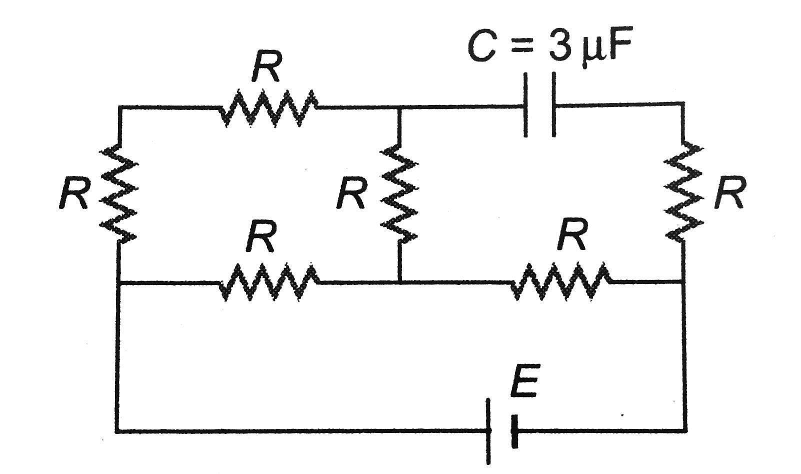 `
`
View SolutionFour identical capacitors are connected in series with a `10 V` battery as shown in the figure. The point `N` is earthed. The potentials of points `A` and `B` are
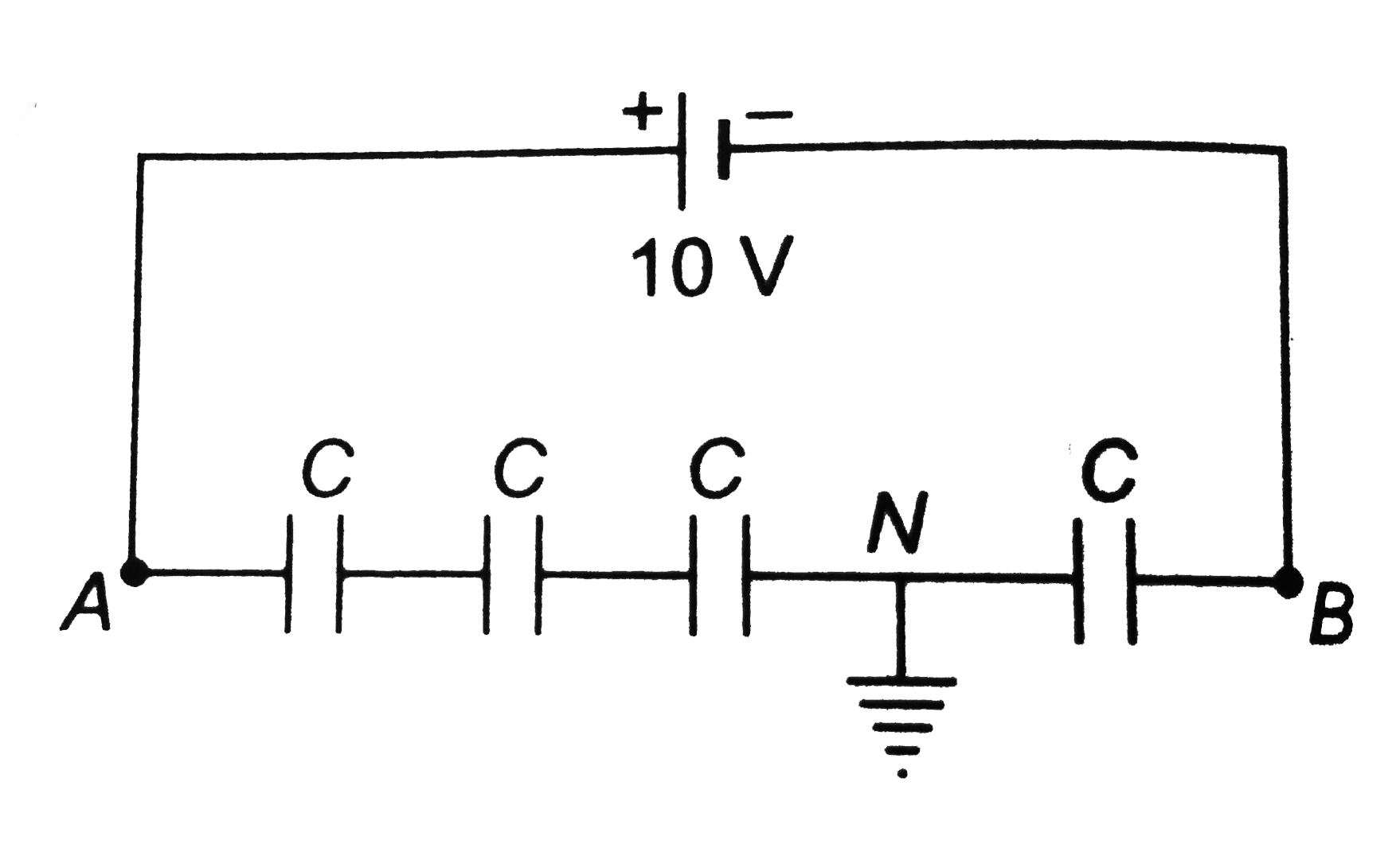 `
`
View SolutionA capacitor of capacity `2muF` is charged to `100 V`. What is the heat ( in mili joule ) generated when this capacitor is connected in parallel to n another capacitor of same capacity?
View SolutionA charged capacitor is discharged through a resistance. The time constant of the circuit is `eta`. Then the value of time constant for the power dissipated through the resistance will be
View SolutionA capacitor is charged by a cell of emf `E` the charging battery is then removed. If an identical capacitor is now inserted in the circuit in parallel with the previous capacitor, the potential difference across the new capacitor is
View SolutionThe potential difference `V_A-V_B` between points `A` and `B` for the circuit segment shown in figure at the given instant is
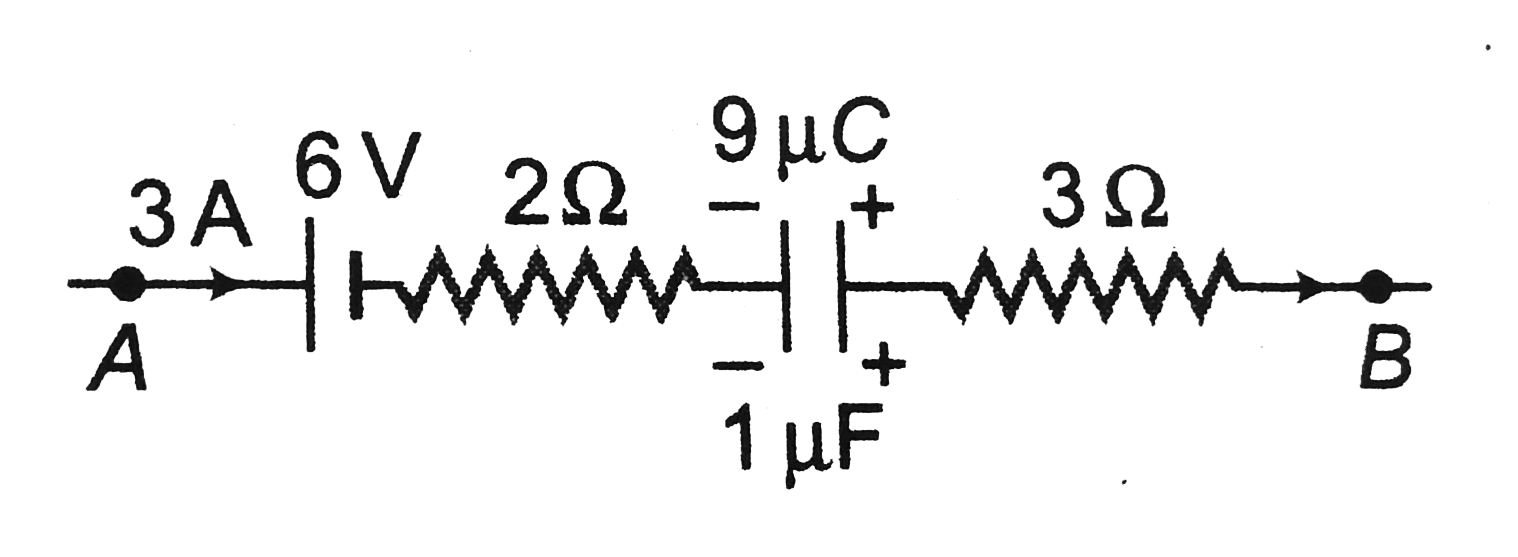 `
`
View SolutionFor the circuit arrangement shown in figure, in the steady state condition charge on the capacitor is
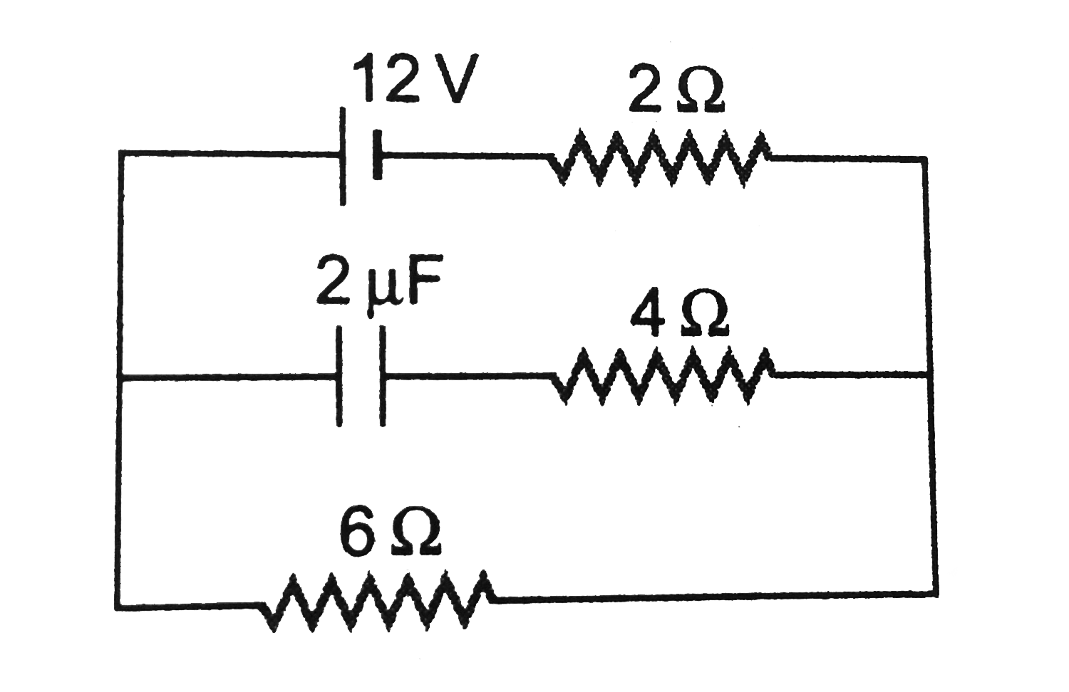 `
`
View SolutionIn the circuit as shown in figure if all the symbols have their usual meanings, then identify the correct statements,
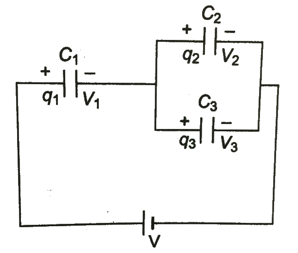 `
`
View SolutionAn electron enters the region between the plates of a parallel plate capacitor at an angle `theta` to the plates. The plate width is `l`, the plate separation is `d`. The electron follows the path shown just missing the upper plate. Neglect gravity. Then,
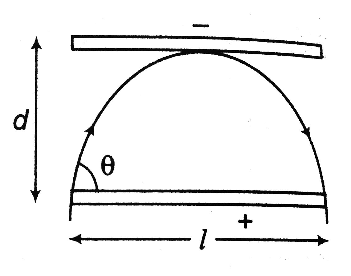 `
`
View SolutionAn infinite sheet of charge has a surfaces charge density of `10^-7C/m^2`. The separation between two equipotential surfce whose potentials differ by `5 V` is
View SolutionFind the equivalent capacitance across `A` and `B` for the arrangement shown in figure. All the capacitors are of capacitance `C`
 `
`
View SolutionThe equivalent capacitance between `X` and `Y` is
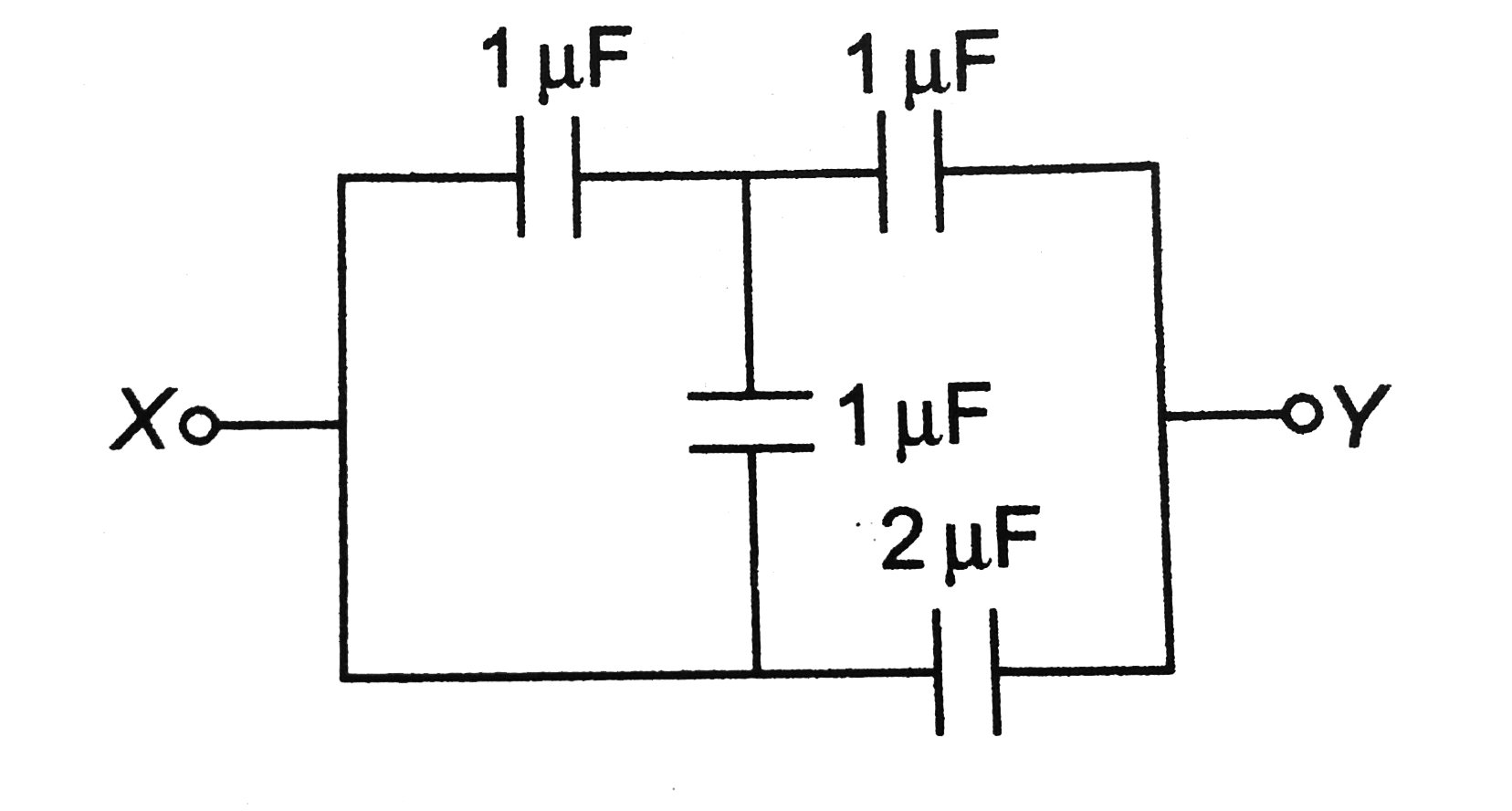 `
`
View SolutionIn the arrangement shown in figure dielectric constant `K_1=2` and `K_2=3`. If the capacitance across `P` and `Q` are `C_1` and `C_2` respectively, then `C_1//C_2` will be (the gaps shown are negligible)
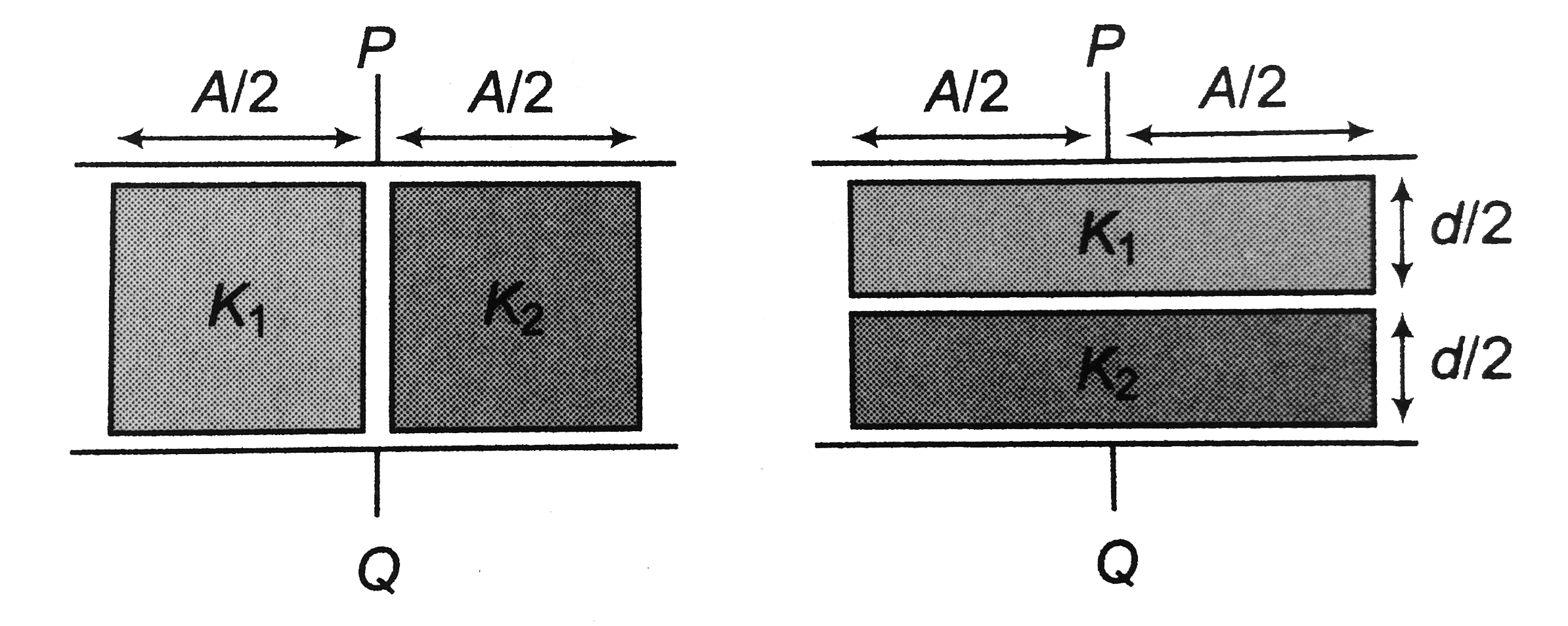 `
`
View SolutionSix equal capacitors each of capacitance C are connected as shown in the figure. The equivalent capacitance between points `A` and `B` is
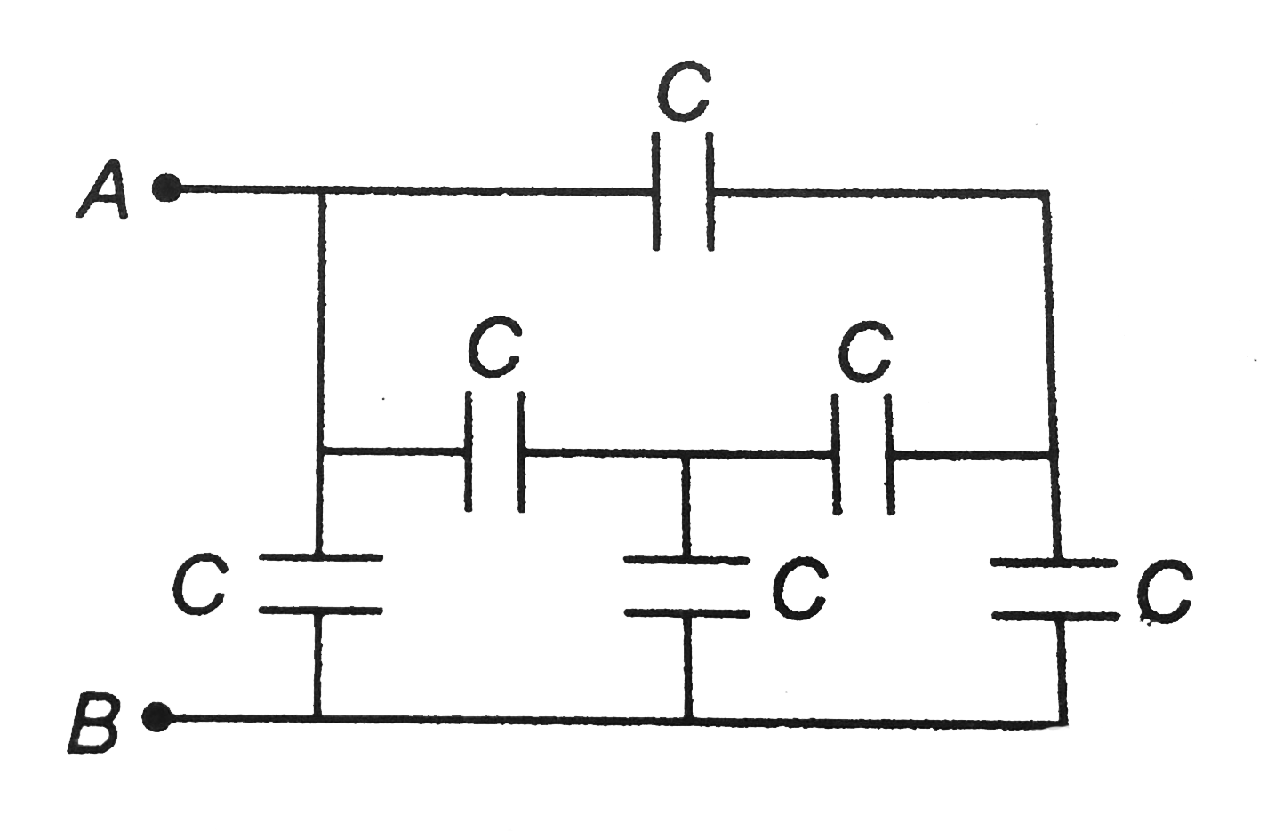 `
`
View SolutionFour ways of making a network of five capacitor of the same value are shown in four choices. Three out of four are identical. The one which is different is
View SolutionThe equivalent capacitance of the arrangement shown in figure, if `A` is the area of each plate is
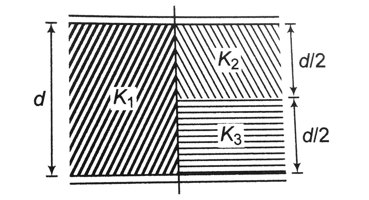
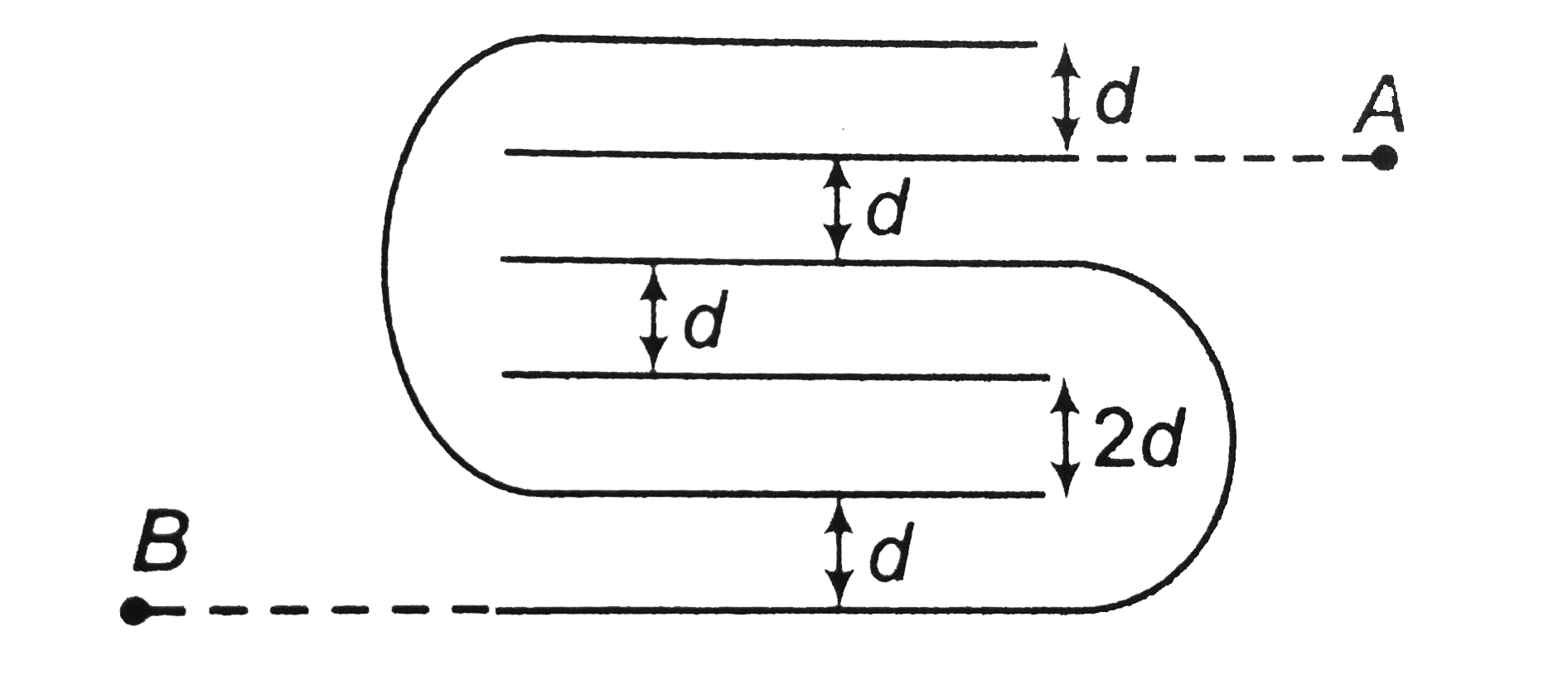
View SolutionFind equivalent capacitance between points `A` and `B`. [Assume each conducting plate is having same dimensions and neglect the thickness of the plate `(epsilon_0A)/d=7muF` where A is area of plate]`
 `
`
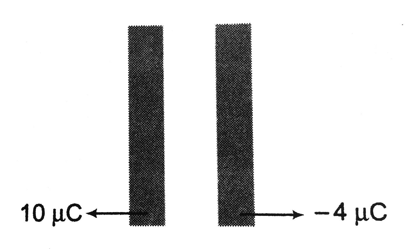
View SolutionTwo metallic plates are kept parallel to one another and charges are given to them as shown in figure. Find the charge on all the four faces.
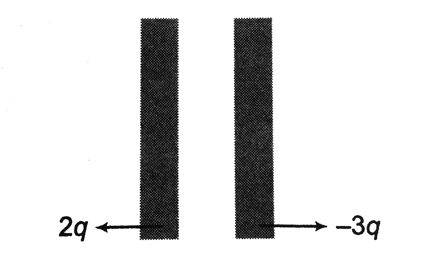
View SolutionCharges `2q` and `-3q` are given to two identical metal plates of area of cross section `A`. the distance between the plates is `d`. Find the capacitance and potential difference between the plates.
View SolutionFind the charged stored in all the capacitors

View SolutionFind the charge stored in the capacitor.
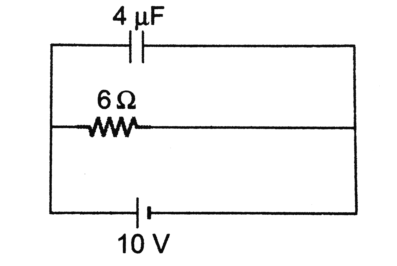
View SolutionFind the charge stored in the capacitor.
View SolutionA `1muF` capacitor and a `2µF` capacitor are connected in series across a `1200 V` supply line.
a. Find the charge on each capacitor and the voltage across them.
b. The charged capacitors are disconnected from the line and from each other and reconnected with terminals of like sign together. Find the final charge on each and the voltage across them.
View SolutionA `100muF` capacitor is charged to `100 V`. After the charging, battery is disconnected. The capacitor is then connected in parallel to another capacitor. The final voltage is `20 V`. Calculate cap the capacity of second capacitor.
View SolutionAn Uncharged capacitor `C` is connected to a battery through a resistance `R`. Show that by the time the capacitor gets fully charged, the energy dissipated in ``R is the same as the energy stored in `C`.
View SolutionHow many time constants will elapse before the current in a charging `R-C` circuit drops to half of its initial value?
View SolutionA capacitor of capacitance `C` is given a charge go. At time `t = 0` it is connected to an uncharged capacitor of equal capacitance through a resistance `R`. Find the charge on the first capacitor and the second capacitor as a function of time `t`. Also plot the corresponding q-t graphs.
View SolutionA capacitor of capacitance as C is given a charge Q. At `t=0`,it is connected to an ideal battery of emf `(epsilon)`through a resistance R. Find the charge on the capacitor at time t.
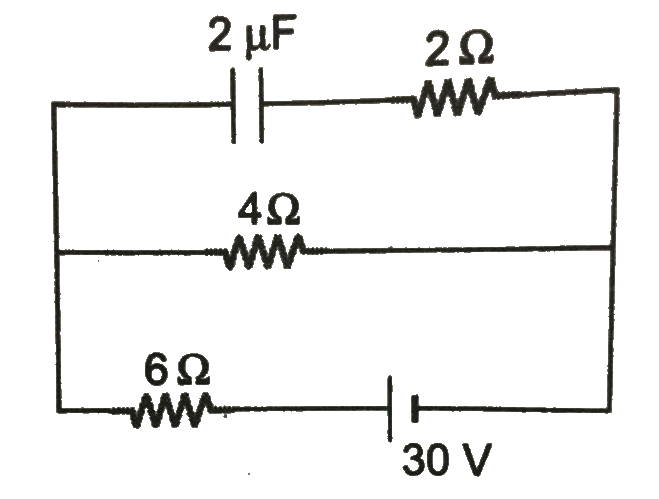
View SolutionDetermine the current through the battery in the circuit shown in figure.
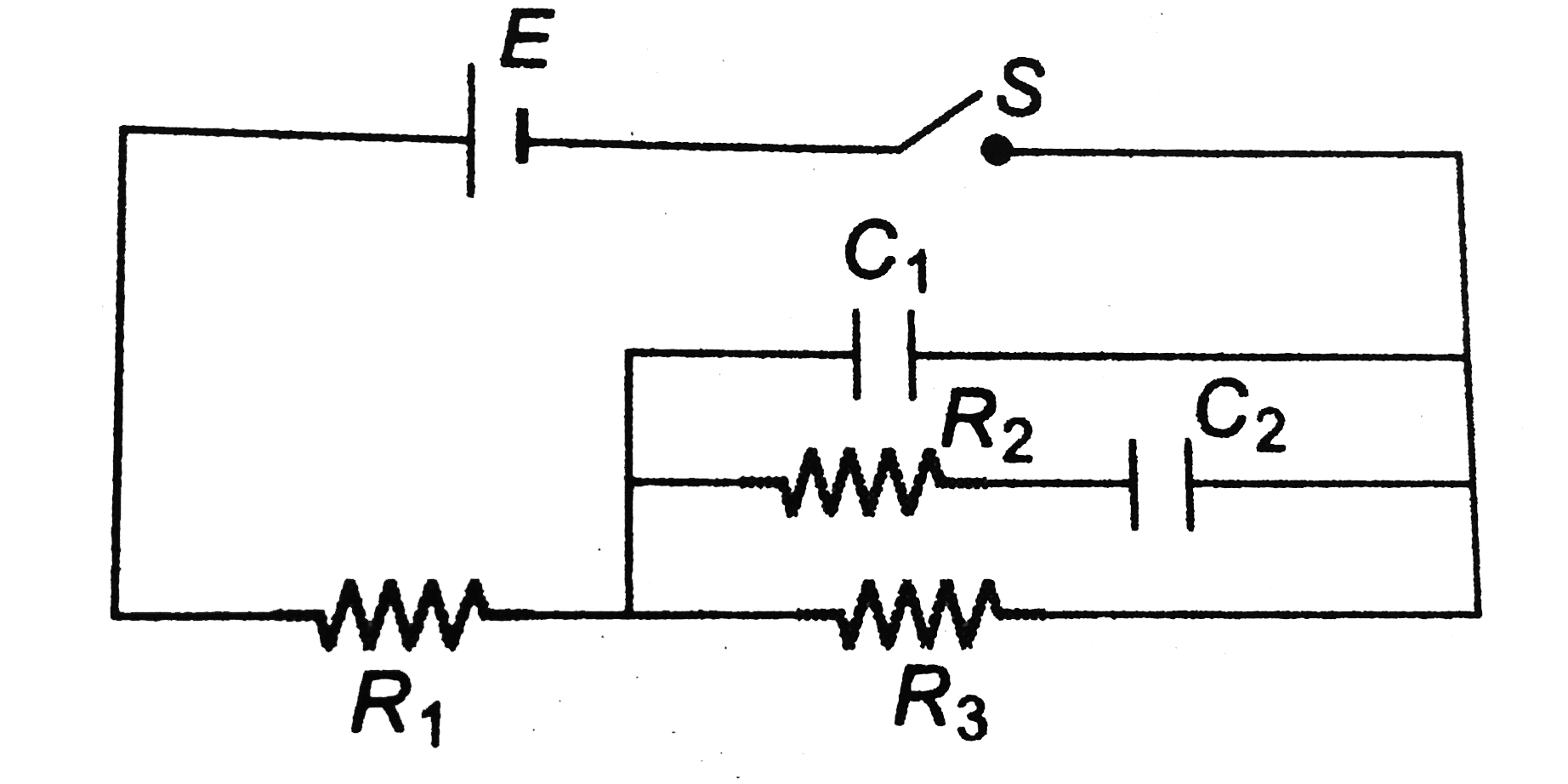
(a) immediately after the switch S is closed
(b) after a long time.
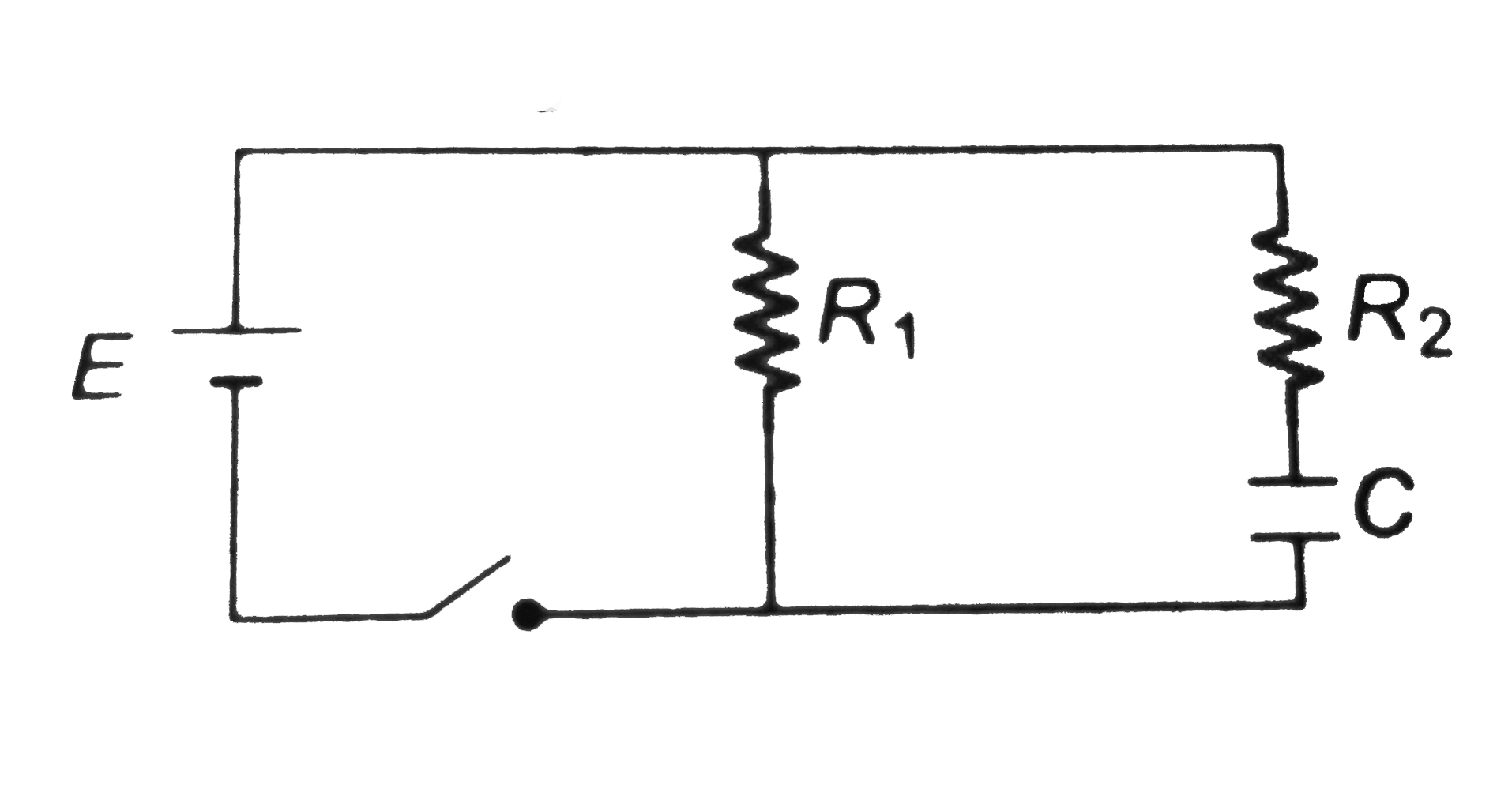
View SolutionFor the circuit shown in figure, find
(a) the initial current through each resistor
(b) steady state current through each resistor
(c) final energy stored in the capacitor
(d) time constant of the circuit when switch is opened.
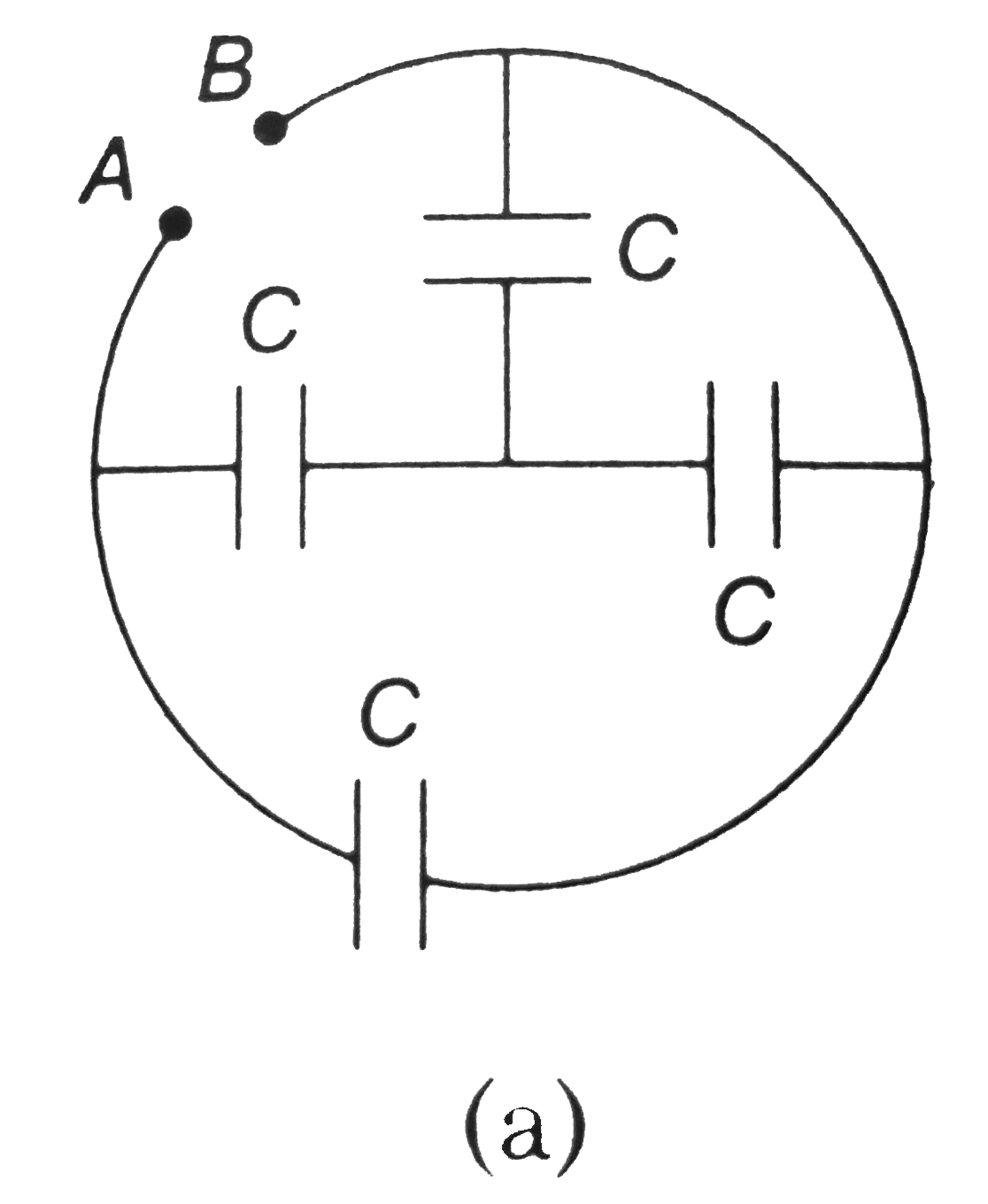
View SolutionFind equivalent capacitance between points `A` and `B`,
View SolutionA `4.00 muF` capacitor and a `6.00muF` capacitor are connected in parallel across a `660 V` supply line
(a) Find the charge on each capacitor and the voltage across each.
(b) The charged capacitors are disconnected from the line and from each other, and reconnected to each other with terminals of unlike sign together. Find the final charge on each and the voltage across each.
View SolutionA `5.80 muF` parallel-plate air capacitor has a plate separation of `5.00 mm` and is charged to a potential difference of `400 V`. Calculate the energy density in the region between the plates, in `J/m^3`
View SolutionThe dielectric to be used in a parallel-plate capacitor has a dielectric constant of 3.60 and a dielectric strength of `1.60 xx 10^7 V//m`. The capacitor is to have a capacitance of `1.25 xx10^-9F` and must be able to withstand a maximum potential difference of `5500 V`. What is the minimum area the plates of the capacitor may have?
View SolutionTwo condensers are in parallel and the energy of the combination is `0.1 J`, when the difference. of potential between terminals is `2 V`. With the same two condensers in series, the energy `1.6 xx 10^-2` J for the same difference of potential across the series combination. What are the capacities?
View SolutionA circuit has section `AB` as shown in figure. The emf of the source equals `E=10V`, the capacitor capacitances are equal to `C_1 =1.0muF` and `C_2=2.0muF`, and the potential difference `V_A-V_B=5.0V`. Find the voltage across each capacitor.

View SolutionSeveral `10 pF` capacitors are given, each capable of withstanding `100 V`. How would you construct :
(a) a unit possessing a capacitance of `2 pF` and capable of withstanding `500 V`?
(b) a unit possessing a capacitance of `20 pF` and capable of withstanding `300 V`?
View SolutionTwo, capacitors `A` and `B` are connected in series across a `100 V` supply and it is observed that the potential difference across them are `60 V` and `40 V`. A capacitor of `2 p.F` capacitance is now connected in parallel with `A` and the potential difference across B rises to `90 V`. Determine the capacitance of `A` and `B`
View SolutionA `10.0muF` parallel-plate capacitor with circular plates is connected to a `12.0 V` battery.
(a) What is the charge on each plate?
(b) How much charge would be on the plates if their separation were doubled while the capacitor remained connected to the battery?
(c) How much charge would be on the plates if the capacitor were connected to the `12.0 V` batter `Y` after the radius of each plate was doubled without changing their separation?
View SolutionA `450 muF` capacitor is charged to `295 V`. Then, a wire is connected between the plates. How many joule of thermal energy are produced as the capacitor discharges if all of the energy th was stored goes into heating the wire?
View SolutionThe plates of a parallel-plate capacitor in vacuum are `5.00 mm` apart and `2.00 m^2` in area. A potential difference of `10,000 V` is applied across the capacitor. Compute
(a) the capacitance
(b) the charge on each plate, and
(c) the magnitude of the electric field in the space between them.
View SolutionThree capacitors having capacitances of `8.4 muF, 8.2muF` and `4.21muF` are connected in series across a 36 potential difference.
(a) What is the charge on `4.2muF` capacitor?
(b) What is the total energy stored in all three capacitors?
(c) The capacitors are disconnected from the potential difference without allowing them to discharge. They are then reconnected in parallel with each other, with the positively charged plates connected together. What is the voltage across each capacitor in the parallel combination?
(d) What is the total energy now stored in the capacitors?
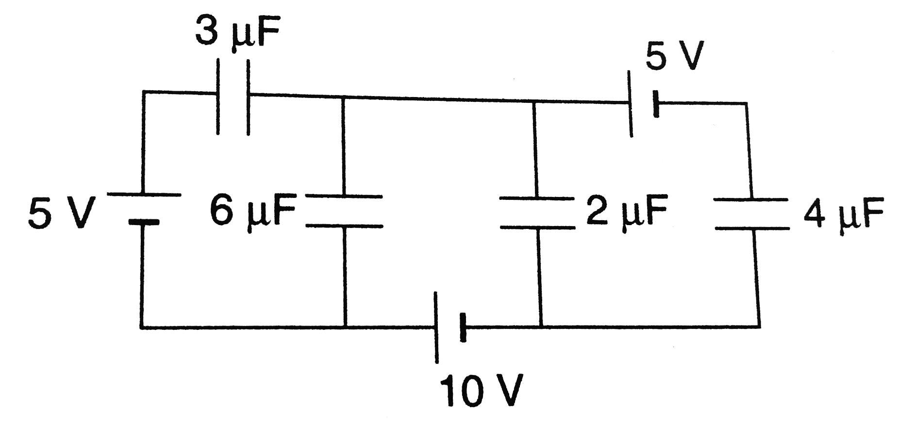
View SolutionFind the charges on `6muF ` and `4muF` capacitors
View SolutionIn figure `C_1=C_5=8.4muF` and `C_2=C_3=C_4=4.2muF`.The applied potential is `V_(ab)=220V`
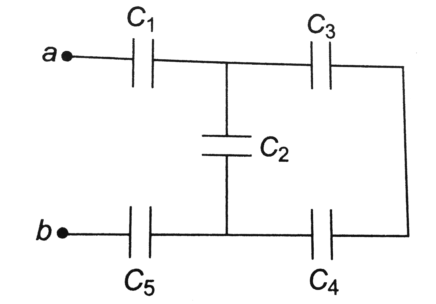
(a) What is the equivalent capacitance of the network between points `a` and `b`?
(b) Calculate the charge on each capacitor and the potential difference across each capacitor.
View SolutionTwo condensers `A` and `B` each having slabs of dielectric constant `K = 2` are connected in series. When they are connected across `230 V` supply, potential difference across `A` is `130 V` and that across B is `100 V`. If the dielectric in the condenser of smaller capacitance is replaced by one for which `K = 5`, what will be the values of potential difference across them?
View SolutionA capacitor of capacitance `C_1 = 1.0muF` charged upto a voltage `V = 110 V` is connected in parallel to the terminals of a circuit consisting of two uncharged capacitors connected in series and possessing the capacitance `C_2 = 2.0 muF` and `C_3 = 3.0muF`. What charge will flow through the connecting wires?
View SolutionIn figure the battery has a potential difference of `20 V`. Find
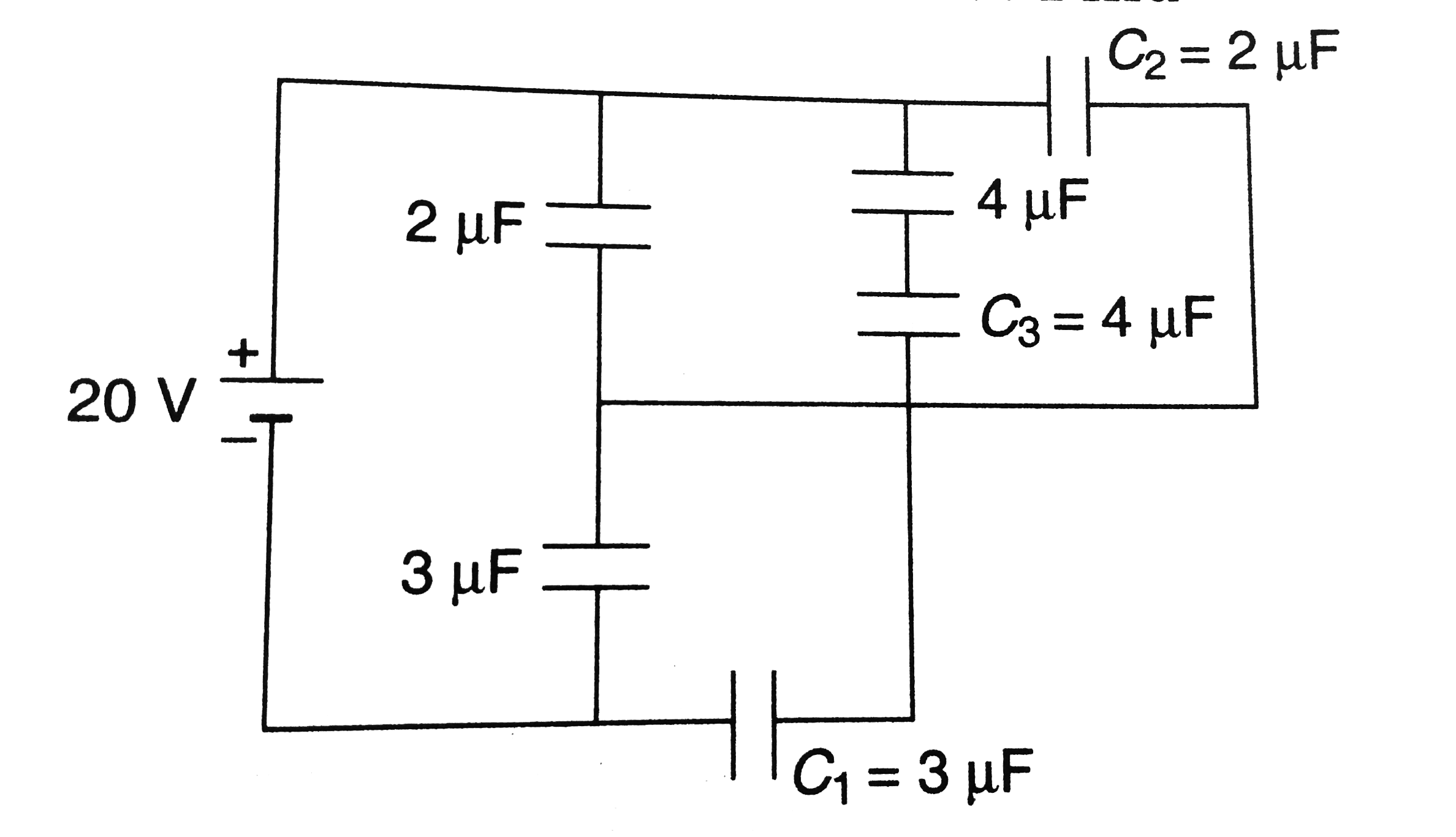
(a) the equivalent capacitance of all the capacitors across the battery and
(b) the charge stored on that, equivalent capacitance. Find the charge on
(c) capacitor 1,
(d) capacitor 2, and
(e) capacitor 3.
View SolutionIn figure, battery B supplies `12 V`. Find the charge on each capacitor
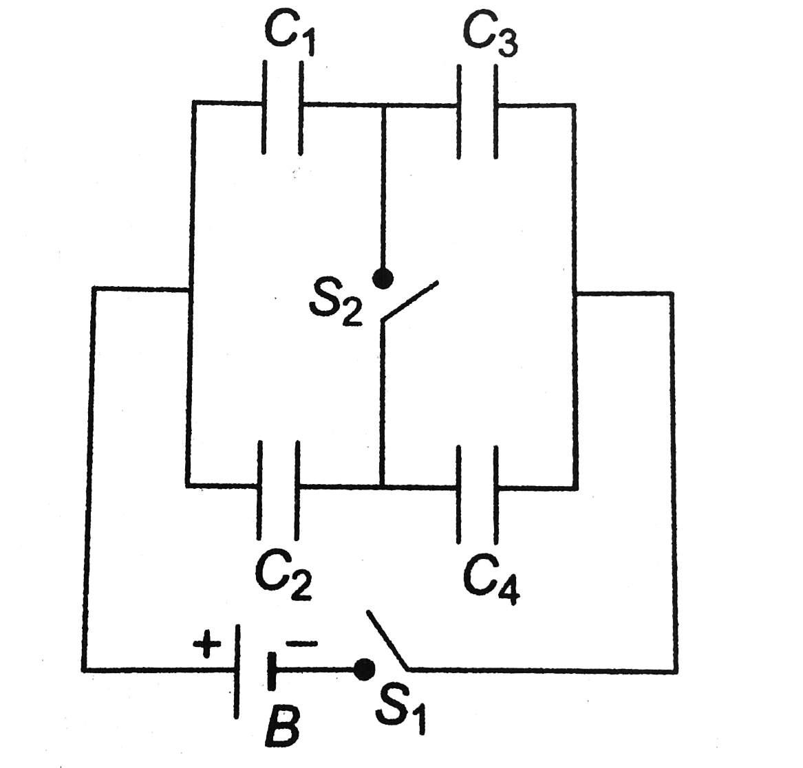
(a) first when only switch S1 is closed and
(b) later when S2 is also closed.
(Take `C_1=1.0muF, C_2=2.0muF, C_3=3.0muF` and `C_4=4.0muF)`
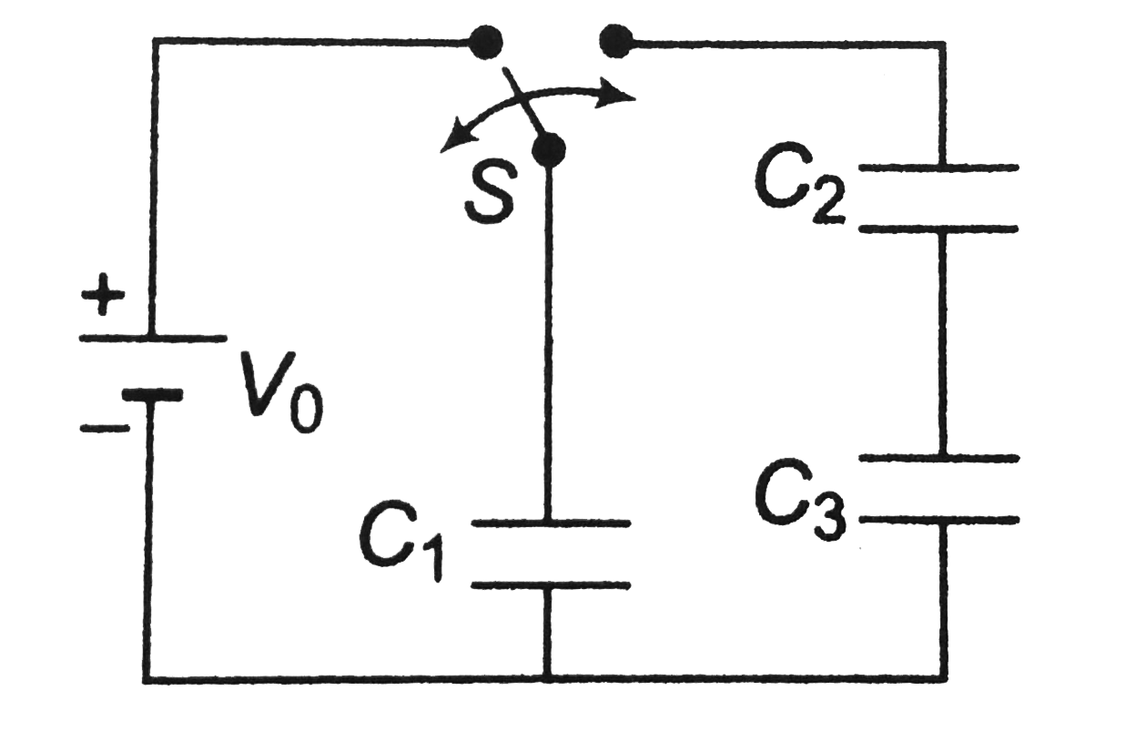
View SolutionWhen switch `S` is thrown to the left in figure, the plates of capacitor 1 acquire a potential difference `V_0`. Capacitors 2 and 3 are initially uncharged. The switch is now thrown to the right. What are the final charges `q_1, q_2` and `q_3` on the capacitors?
View SolutionA parallel-plate capacitor has plates of area `A` and separation `d` and is charged to a potential difference `V`. The charging battery is then disconnected, and the plates are pulled apart until their separation is `2d`. Derive expression in terms of `A, d` and `V` for
(a) the new potential difference
(b) the initial and final stored energies, `U_i` and `U_f` and
(c) the work required to increase the separation of plates from d to `2d`.
View SolutionIn the circuit shown in figure `E_1, 2E_2=20V, R_1=R_2=10kOmega` and `C=1muF`. Find the current through `R_1,R_2` and `C` when
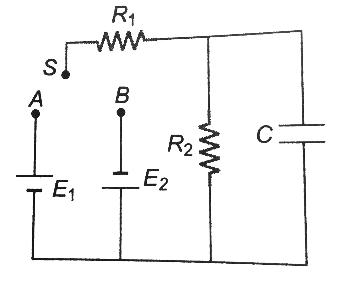
(a) `S` has been kept connected to `A` for a long time.
(b) The switch is suddenly shifted to `B`.
View Solution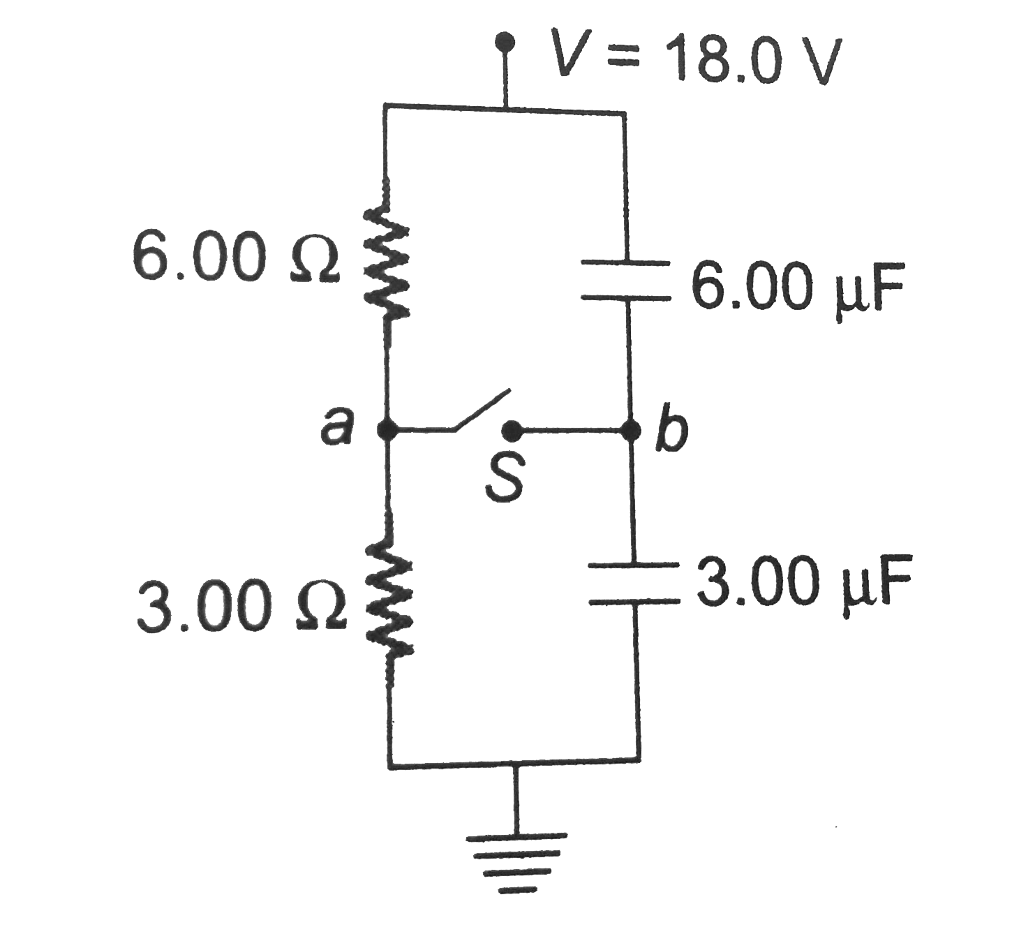
(a) What is the potential of point a with respect to point b in figure, when switch `S` is open?
(b) Which point, `a` or `b`, is at the higher potential?
(c) What is the final potential of point `b` with respect to ground when switch S is closed?
(d) How much charge flows through switch `S` when it is closed?
View Solution
(a) What is the potential of point a with respect to point b in figure, when switch `S` is open?
(b) Which point, `a` or `b`, is at the higher potential?
(c) What is the final potential of point `b` with respect to ground when switch S is closed?
(d) How much charge flows through switch `S` when it is closed?
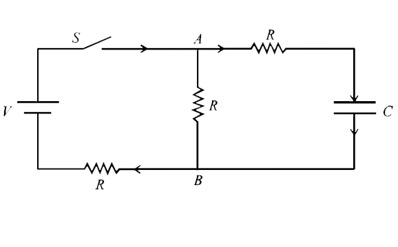
View SolutionIn the circuit shown in Figure, the battery is an ideal one, with emf V. The capacitor is initially uncharged. The switch S is closed at time t = 0 .
(a) Find the charge Q on the capacitor at time t.
(b) Find the current in AB at time t. What is its limiting value as `t rarr oo`:
 .
.
View SolutionTwo very large thin conducting plates having same cross sectional area are placed as shown in figure. They are carrying charges `Q` and `3Q`, respectively. The variation of electric field as a function at x (for `x=0` to `x=3d`) will be best represented by
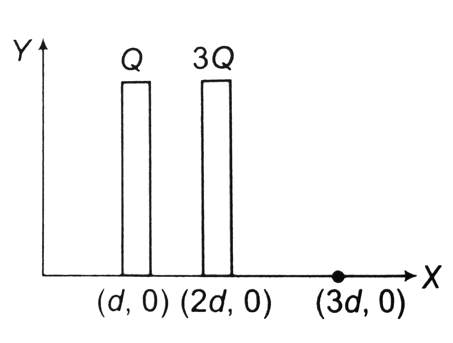
View SolutionThe electric field on two sides of a thin sheet of charge is shown in the figure. The charge density on the sheet is
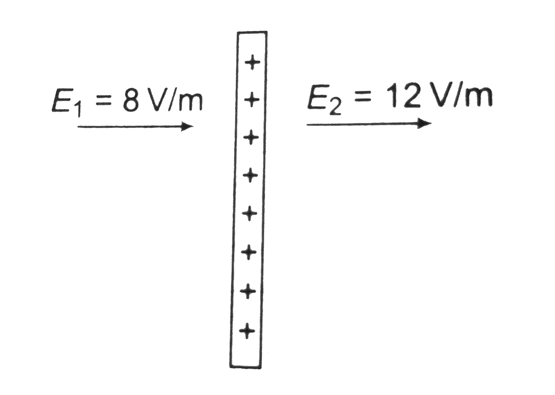
View SolutionIn the circuit shown in figure, the capacitors are initially uncharged. The current through resistor PQ just after closing the switch is
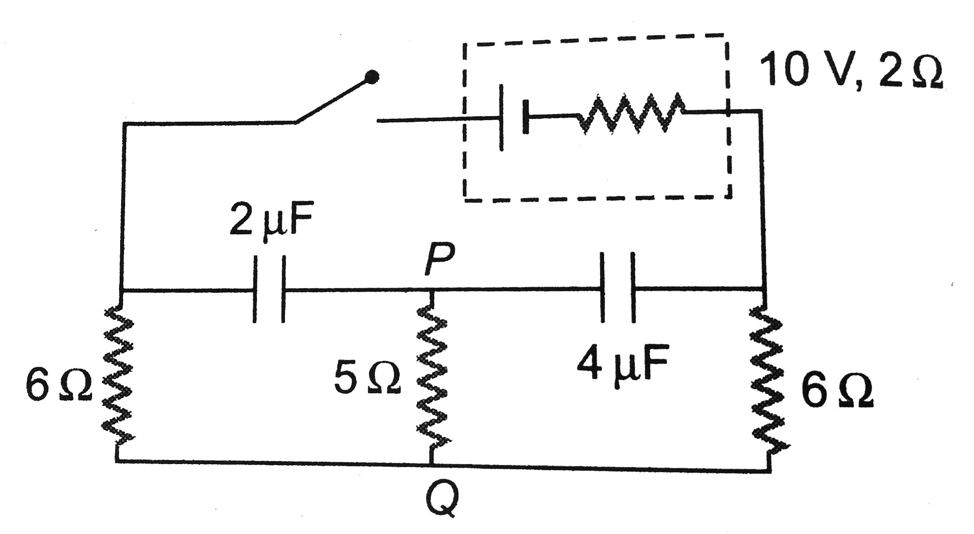
View SolutionA graph between current and time during charging of a capacitor by a battery in series with a resistor is shown. The graphs are drawn for two circutis. `R_1, R_2, C_1, C_2` and `V_1, V_2` are the values of resistance, capacitance and `EMF` of the cell in the two circuits. If only two parameters (out of resistance, capacitance, `EMF`) are different in the two circuits. What may be the correct options (s) ?
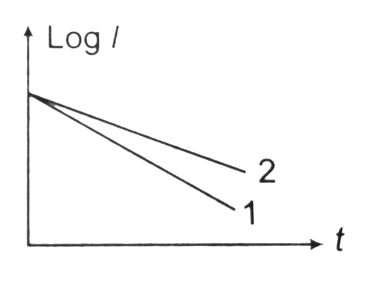
View SolutionA capacitor of capacitance `C` is charge by a battery of emf `E` and internal resistance r. A resistasnce 2 is also connet in sereis with the capacitor. The amount of heat liberated inside the battery by the time capacitor is `50%` charged is
View SolutionFor the circuit shown in the figure determine the charge on capacitor in steady state.
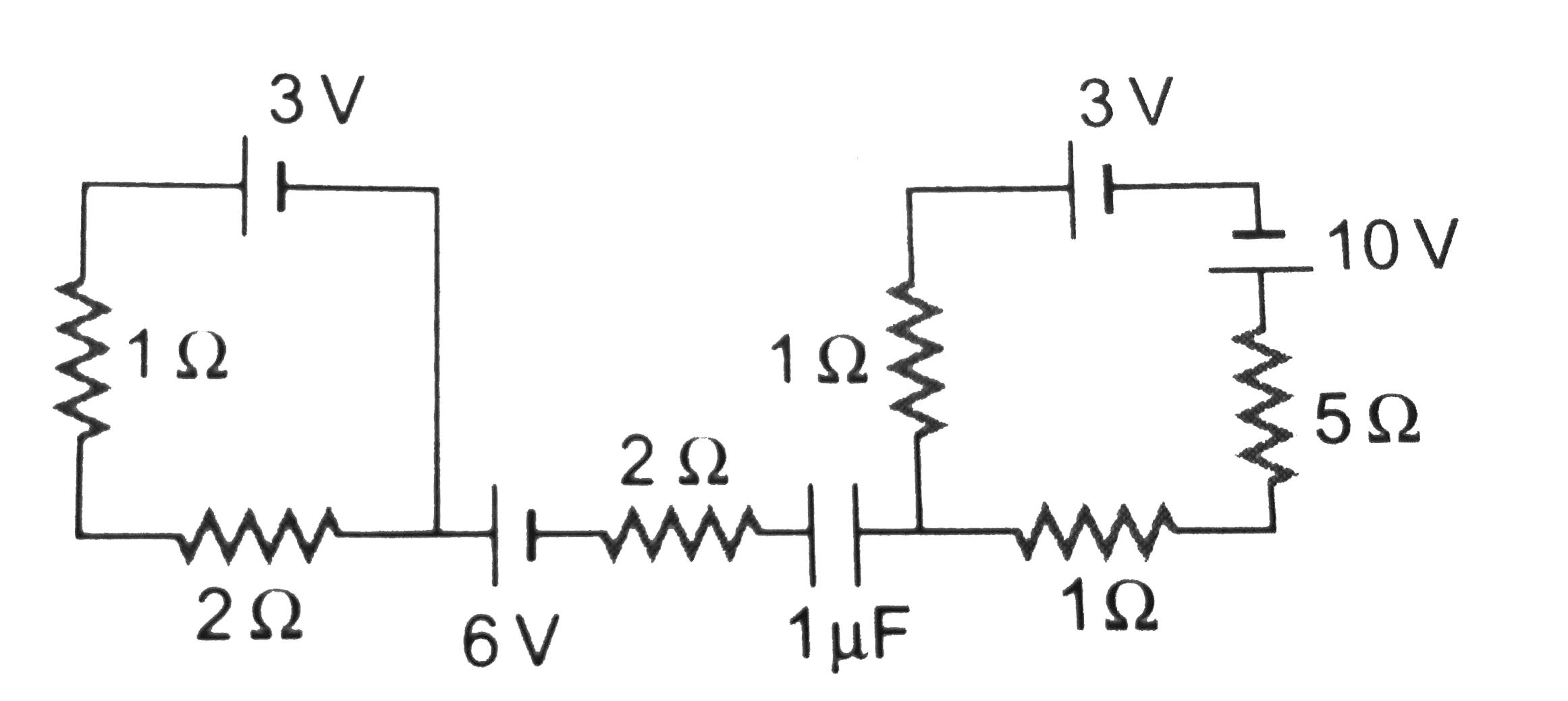
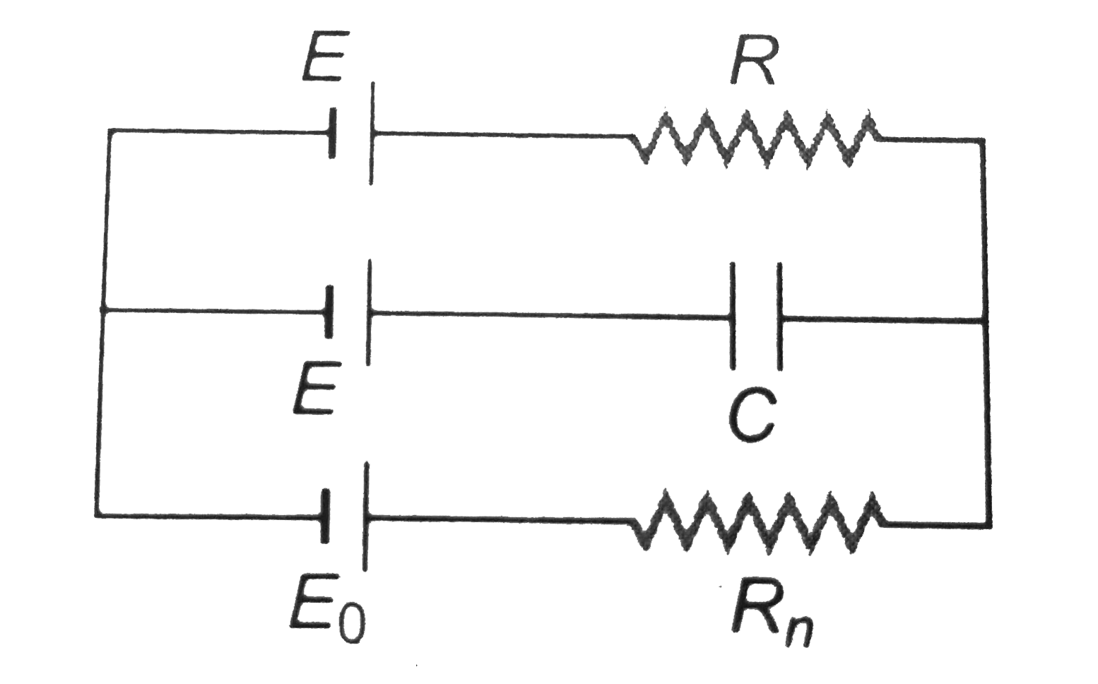
View SolutionFor the circuit shown in the figure, find the charge stored on capacitor in steady state.
View SolutionTwo similar parallel plate capacitors each of capaciti `C_0` are connected in series The combination is connected with a voltage source of `V_0`. Now, seperation between the plates of one capacitor is increased by a distance `d` and the separation between the plates of another capacitor is decreased by the distance `d/2`. The distance between the plates of each capacitor was `d` before the chane in sepration. Then select the correct choice.
View SolutionThe switch shown n the figure is closed at `t=0`. The charge on the capacitor as a function of time is given by
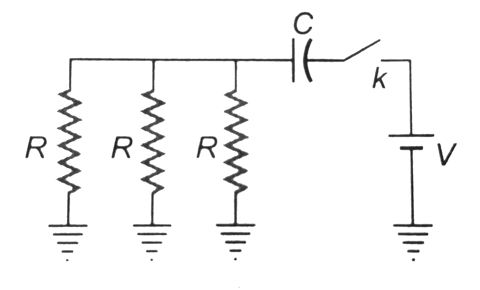
View SolutionA `2muF` capacitor `C_1` is charge to a voltage 100 V and a `4muF capacitor `C_2` is charged to a voltasge `50 V`. The capacitors are then connected in parallel What is the loss of energy due to parallel connection?
View SolutionThe figure shows a graph of the current in a charging circuit of a capacitor through a resistor of resistance `10Omega`.
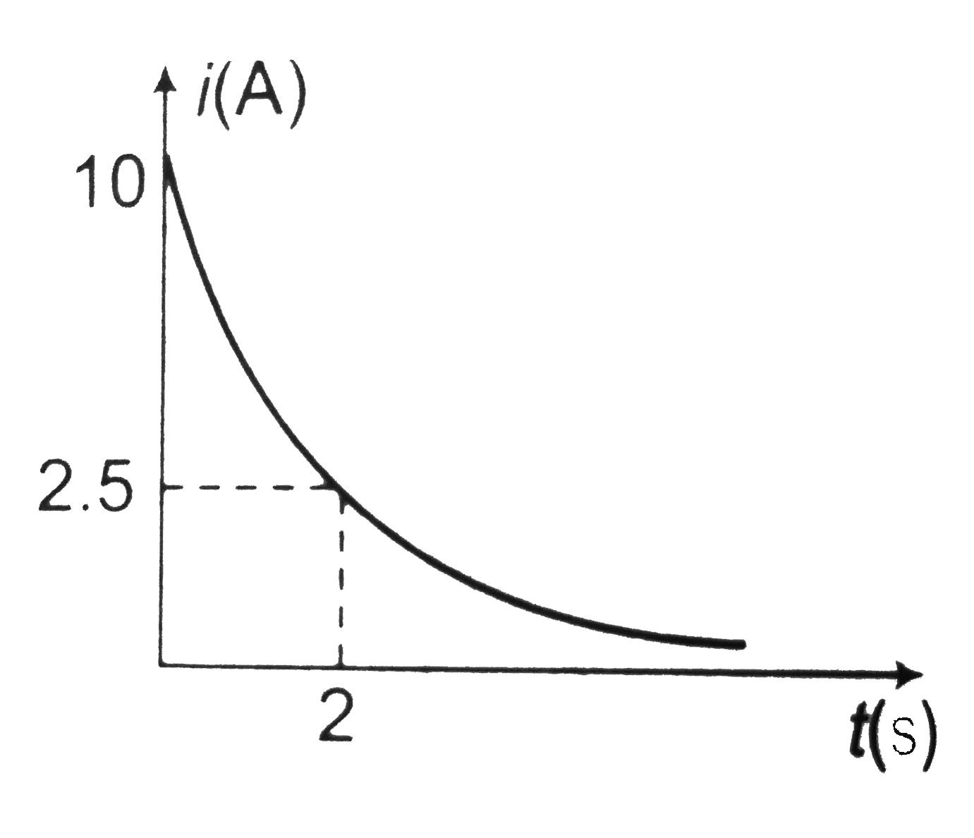
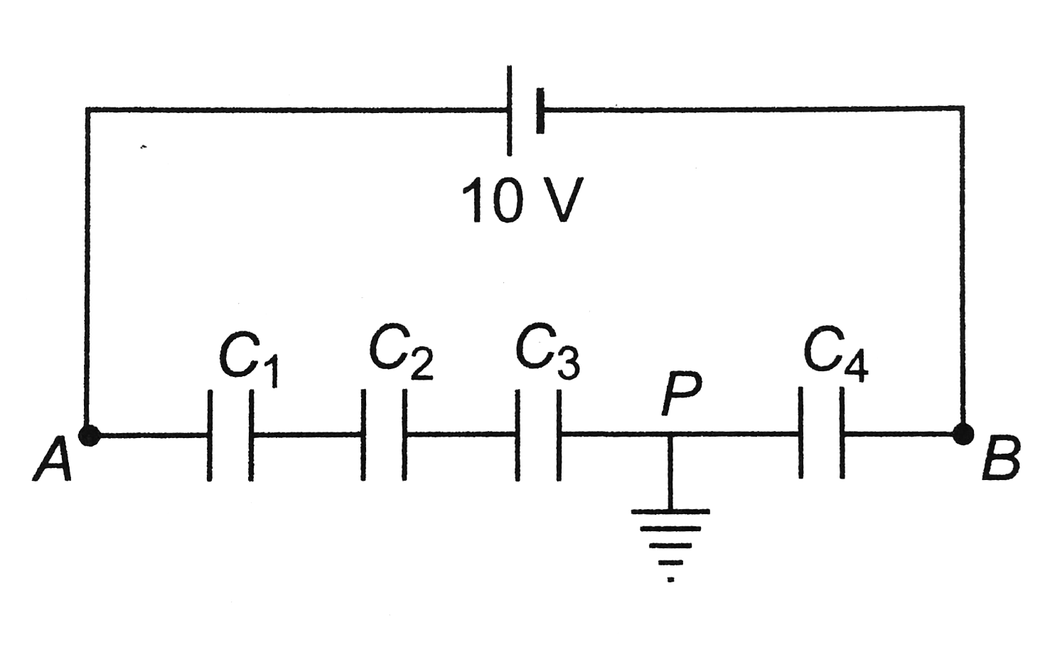
View SolutionFour capacitors are connected inseries a battery of emf `10 V` as shown in the figure. The point `P` is earthed. The potential of point `A` is equal in magnitude to potetial of points `B` but opposite in sign is
View SolutionA capacitor of capacity `C` is charged to a potential difference `V` and another capacitor of capacity `2C` is charged to a potential difference `4V`. The charged batteries are disconnected and the two capacitors are connected with reverse polarity (i.e. positive plate of first capacitor is connected to negative plate of second capacitor). The heat produced during the redistribution of charge between the capacitors will be
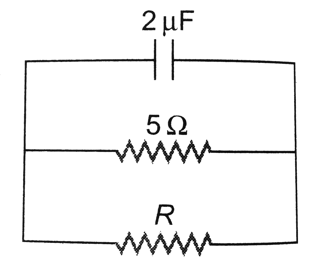
View SolutionA capacitor of capacitance `2muF` is charged to a potential difference of `5V`. Now, the charging battery is disconected and the capacitor is connected in parallel to a resistor of `5Omega` and another unknown resistor of resistance `R` as shown in figure. If the total heat produced in `5Omega` resistance is `10muJ` then the unknown resistance `R` is equal to
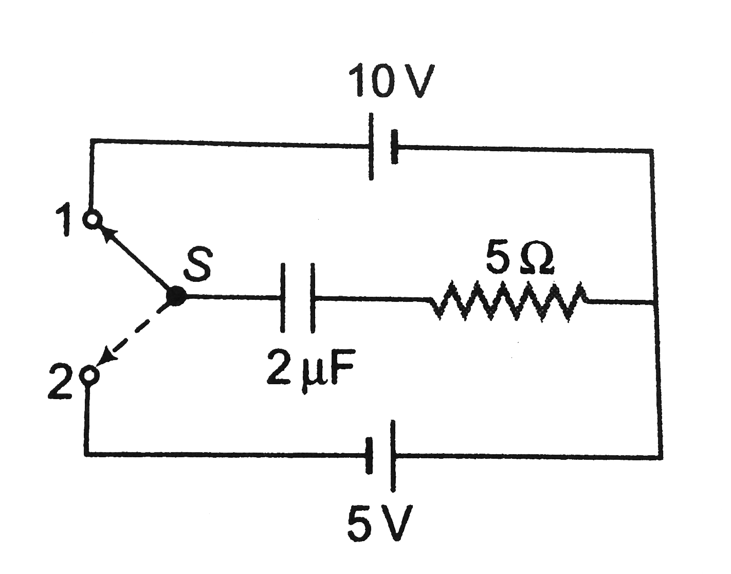
View SolutionIn the circuit shown in figure switch `S` is thrown to position 1 at `t=0`. when the current in the resistor is `1A`, it is shifted to position 2. the total heat generated in the circuit after shifting to position 2 is
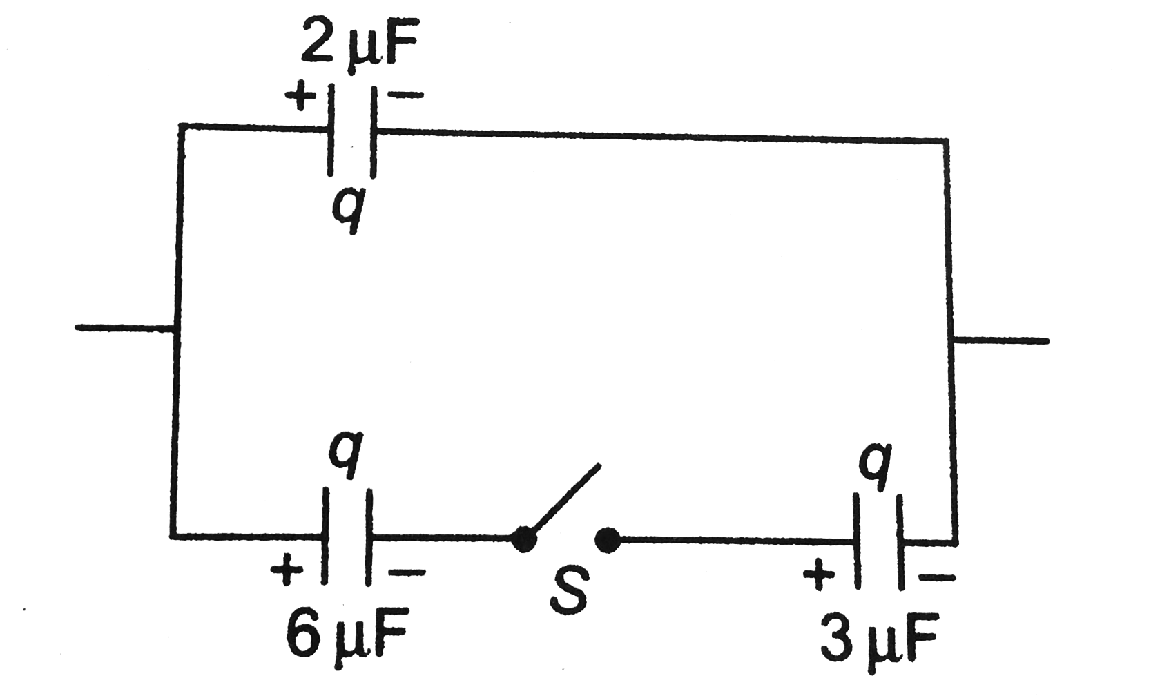
View SolutionThe flow of charge through switch `S` if it is closed is
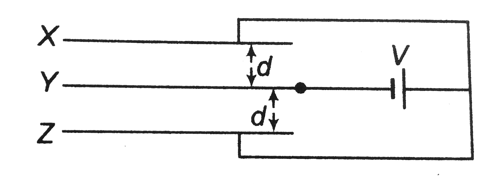
View SolutionConsider the arrangement of three plates `X,Y` and `Z` each of the area `A` and separatioin `d`. The energy sotred when the plates are fully charged is
View SolutionConsider a capacitor charging circuit. Let `Q_1` be the charge given to the capacitor in time interval of `20 ms` and `Q_2` be the charge given in the next time interval of `20ms`. Let 10`muC` charge be deposited in a time interval `t_1` and the next `10muC` charges is deposited in the next time interval `t_2`. Then
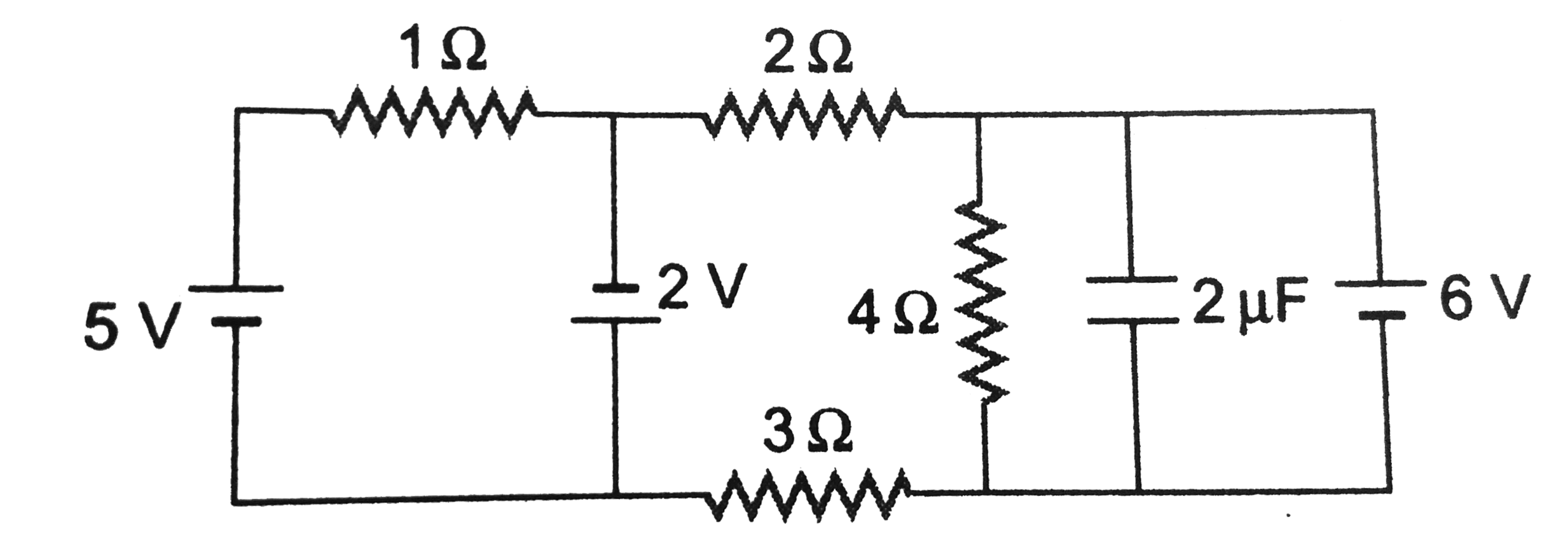
View SolutionThe current in `1Omega` resistance and charge stored in the capacitor are
View Solution
Exercise questions and complete solutions for chapter CAPACITORS of DC PANDEY PHYSICS (HINGLISH) of Class 12