Complete Solutions to Single Answer Questions Level -VI of chapter ELECTRO MAGNETIC INDUCTION of Class 12 book with complete answers and questions
| Class 12 | PHYSICS |
| Chapter | ELECTRO MAGNETIC INDUCTION |
| NARAYANA | Single Answer Questions Level -VI |
| Number Of Questions | 13 |
| Academic Year | 2023-24 |
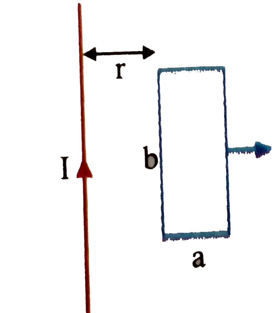
A rectangular loop of wire with dimensions shown in figure is coplanar with a long wire carrying current `'I'`. The distance between the wire and the left side of the loop is `r`. The loop is pulled to the right as indicated. What are the directions of the induced current in the loop and the magnetic forces on the left and right sides of the loop when the loop is pulled ?
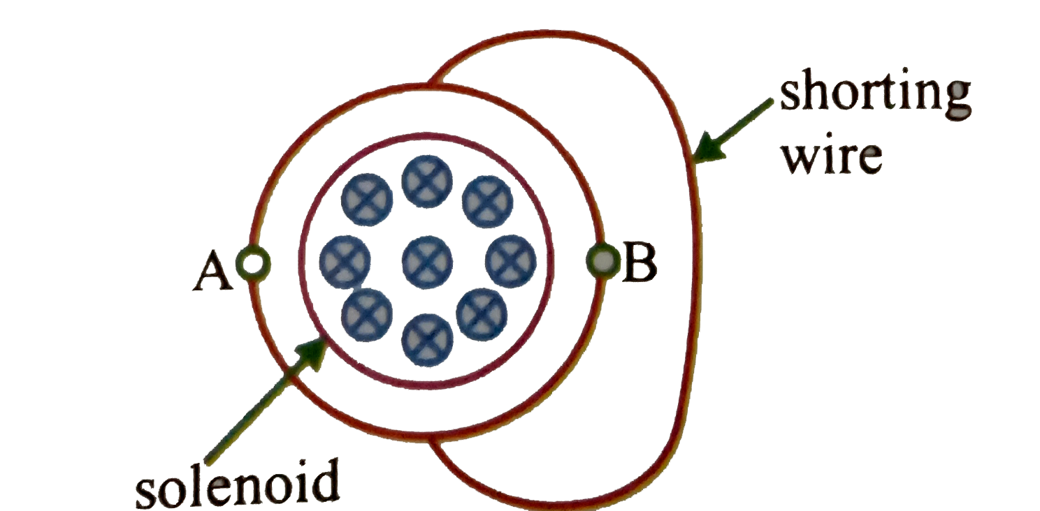
View SolutionA very long solenoid with its axis perpendicular to the page generates an inward magnetic field whose magnitude increases with time. This induces an emf in a conducting wire loop around the solenoid which lights two identical bulbs `A` and `B` connected in series along the wire. Now two points dimetrically opposite on the wire loop are shorted with another conducting wire (having zero resistance) lying to the right og bulb `B` in the plane of the page. After the shorting wire is inserted:
View SolutionA coil having `N` turns is would tightly in the form of a spiral with inner and outer radii a and `b` respectively. When a current `I` passes through the coil, the magnetic field at the centre is.
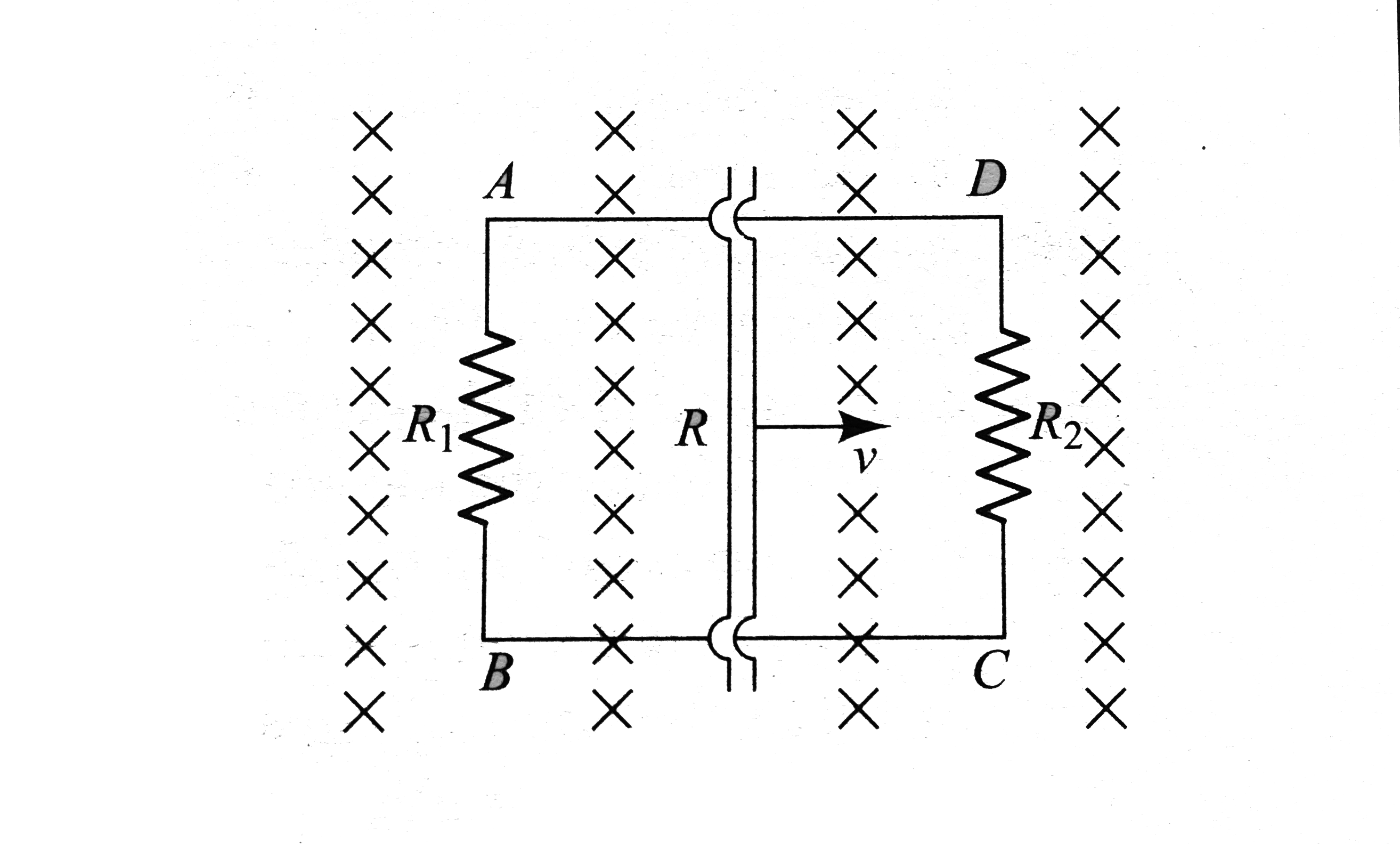
View SolutionA rectangular loop with a sliding conductor of length `l` is located in a uniform magnetic field perpendicular to the plane of the loop . The magneitc inducetion is `b`. The resistances `R_(1)` and `R_(2)`, respectively. Find the current through the conductor during its motion to the right with a constant velocity `v`.
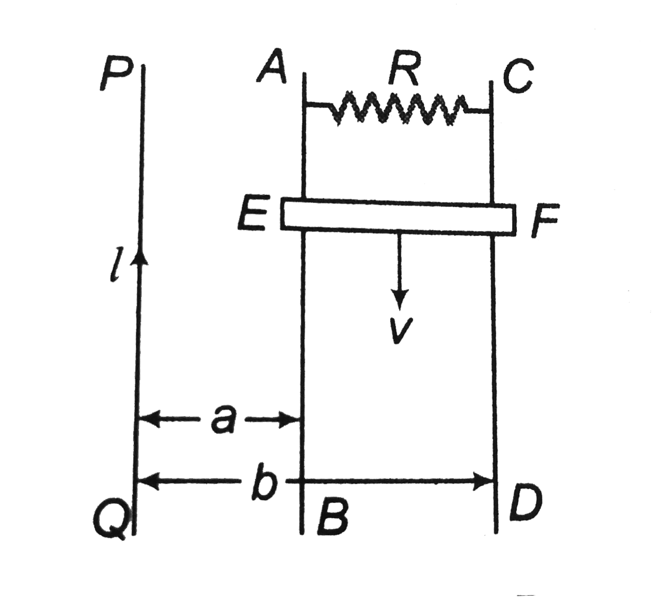
View Solution`PQ` is an infinite current carrying conductor. `AB` and `CD` are smooth conducting rods on which a conductor `EF` moves with constant velocity `v` as shown. The force needed to maintain constant speed of `EF` is
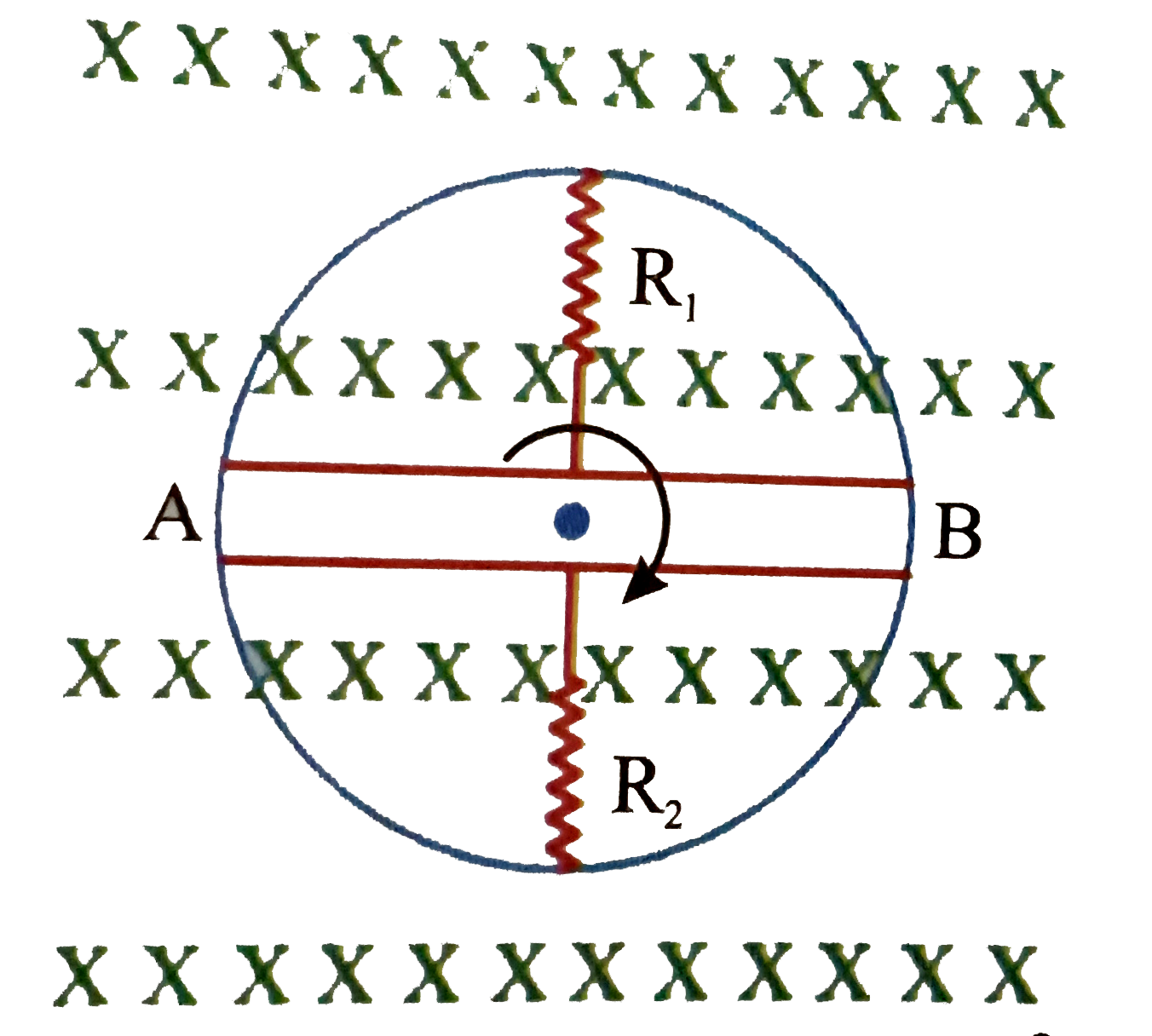
View Solution`AB` is a resistanceless conducting rod which forms a diameter of a conducting ring of radius `r` rotating in a uniform magnetic field `B` as shown in figure. The resistance `R_(1)` and `R_(2)` do not rotate. Then the current through the resistor `R_(1)` is
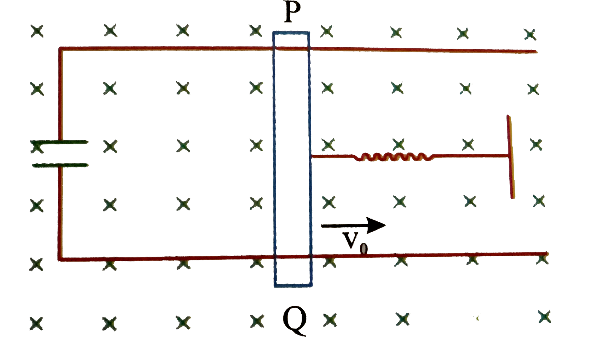
View SolutionA conducting rod `PQ` of mass `m` and length `l` is placed on two long parallel (smooth and conducting) rails connected to a capacitor as shown. The rod `PQ` is connected to a non conducting spring of spring constant `k`, which is initially in relaxed state. The entire arrangement is placed in a magnetic feild perpendicular to the plane of figure.
Neglect the resistance of the rails and rod.
Now, the rod is imparted a velocity `v_(0)` towards right, then acceleration of the rod as a function of its displacement `x` given by
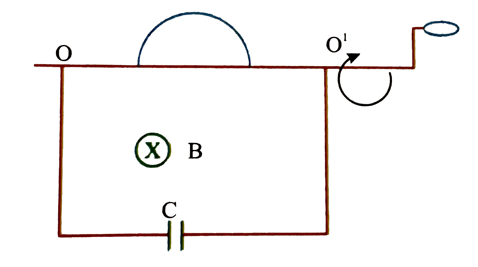
View SolutionA copper rod is bent inot a semi-circle of radius a and at ends straight parts are bent along diameter of the semi-circle and are passed through fixed, smooth and conducting ring `O` and `O'` as shown in figure. A capacitor having capacitance `C` is connected to the rings. The system is located in a uniform magnetic field of induction `B` such that axis of rotation `O O'` is perpendicular to the field direction. At initial moment of time `(t = 0)`, plane of semi-circle was normal to the field direction and the semi-circle is set in rotation with constant angular velocity `omega`. Neglect the resistance and inductance of the circuit. The current flowing through the circuit as function of time is
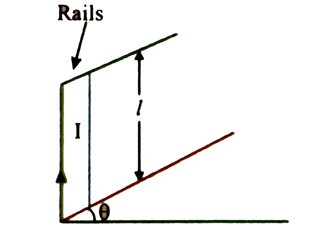
View SolutionA conducting wire of length `l` and mass `m` is placed on two inclined rails as shown in figure. A current `I` is flowig in the wire in the direction shown When no magnetic field is present in the region, the wire is just on the verge of sliding. When a vertically upward magnetic field is switched on, the wire starts moving up the incline. The distance travelled by the wire as a function of time `t` will be
View SolutionA rigid wire loop of square shape having side of length L and resistance R is moving along the x-axis with a constant velocity `v_(0)` in the plane of the paper. At `t =0`, the right edge of the loop enters a region of length 3L where there is a uniform magnetic field `B_(0)` into the plane of the paper, as shown in the figure. For sufficiently large `v_(0)` the loop eventually crosses the region. Let x be the location of the right edge of the loop. Let v(x), I(x) and F(x) represent the velocity of the loop, current in the loop, and force on the loop, respectively, as a function of x. Counter-clockwise current is taken as positive.
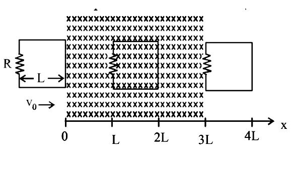 . Which of the following schematic plot(s) is (are) correct? (Ignore gravity)
View SolutionAn ideal inductor, (having initial current zero) a resistor and an ideal battery are connected in series at time `t = 0`. At any time `t`, the battery supplies energy at the rate `P_(B)`, the resistor dissipates energy at the rate `P_(R )` and the inductor stores enegy at the rate `P_(L)`.
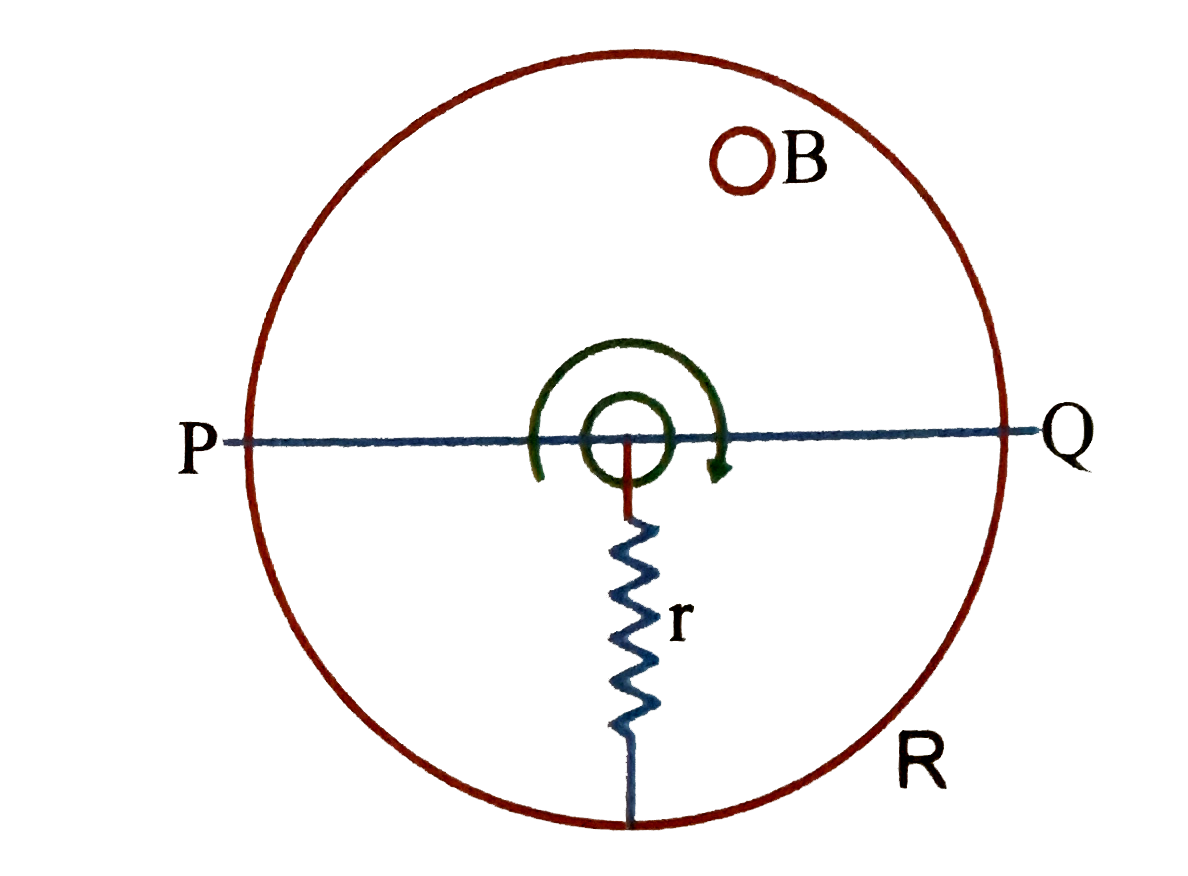
View SolutionIn the figure shown `'R'` is a fixed conducting fixed ring of negligible resistance and radius `'a'` `PQ` is a uniform rod of resistance `r`. It is hinged at the centre of the ring and rotated about this point in clockwise direction with a uniform angular velocity `w`. These is a uniform magnetic filled of strength `'B'` ponting inwards. `'r'` is a stationary resistance
View SolutionA conducting rod of length is moved at constant velocity `v_(0)` on two parallel, conducting, smooth, fixed rails, that are placed in a uniform constant magnetic field B perpendicular to the plane for the rails as shown in Fig. A resistance R is connected between the two ends of the rails.
Then which of the following is/are correct:

View Solution
Single Answer Questions Level -VI questions and complete solutions for chapter ELECTRO MAGNETIC INDUCTION of NARAYANA PHYSICS (HINGLISH) of Class 12