Complete Solutions to Level - III of chapter ELECTRO MAGNETIC INDUCTION of Class 12 book with complete answers and questions
| Class 12 | PHYSICS |
| Chapter | ELECTRO MAGNETIC INDUCTION |
| NARAYANA | Level - III |
| Number Of Questions | 64 |
| Academic Year | 2023-24 |
A magnetic field in a certain region is given by `B = (40 hat(i) - 15 hat(k)) xx 10^(-4) T`. The magnetic flux passes through a loop of area `5.0 cm^(2)` is placed flat on `xy` plane is
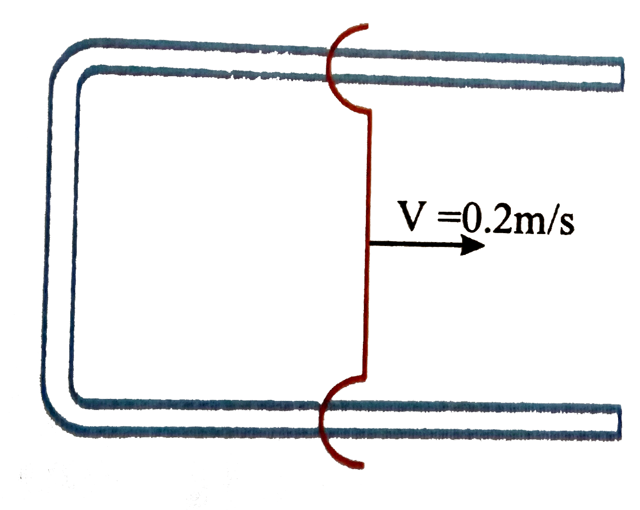
View SolutionA straight conducting rod of length `30 cm` and having a resistance of `0.2` ohm is allowed to slide over two parallel thick metallic rails with uniform velocity of `0.2 m//s` as shown in the figure. The rails are situated in a horizontal plane if the horizontal component of earth's magnetic field is `0.3 xx 10^(-4)T` and a steady current of `3 muA` is induced through the rod. The angle of dip will be:
View SolutionA `0.1 m` long conductor carrying a current of `50 A` is perpendicular to a magentic field of `1.25 mT`. The mechanical power to move the conductor with a speed of `1ms^(-1)` is
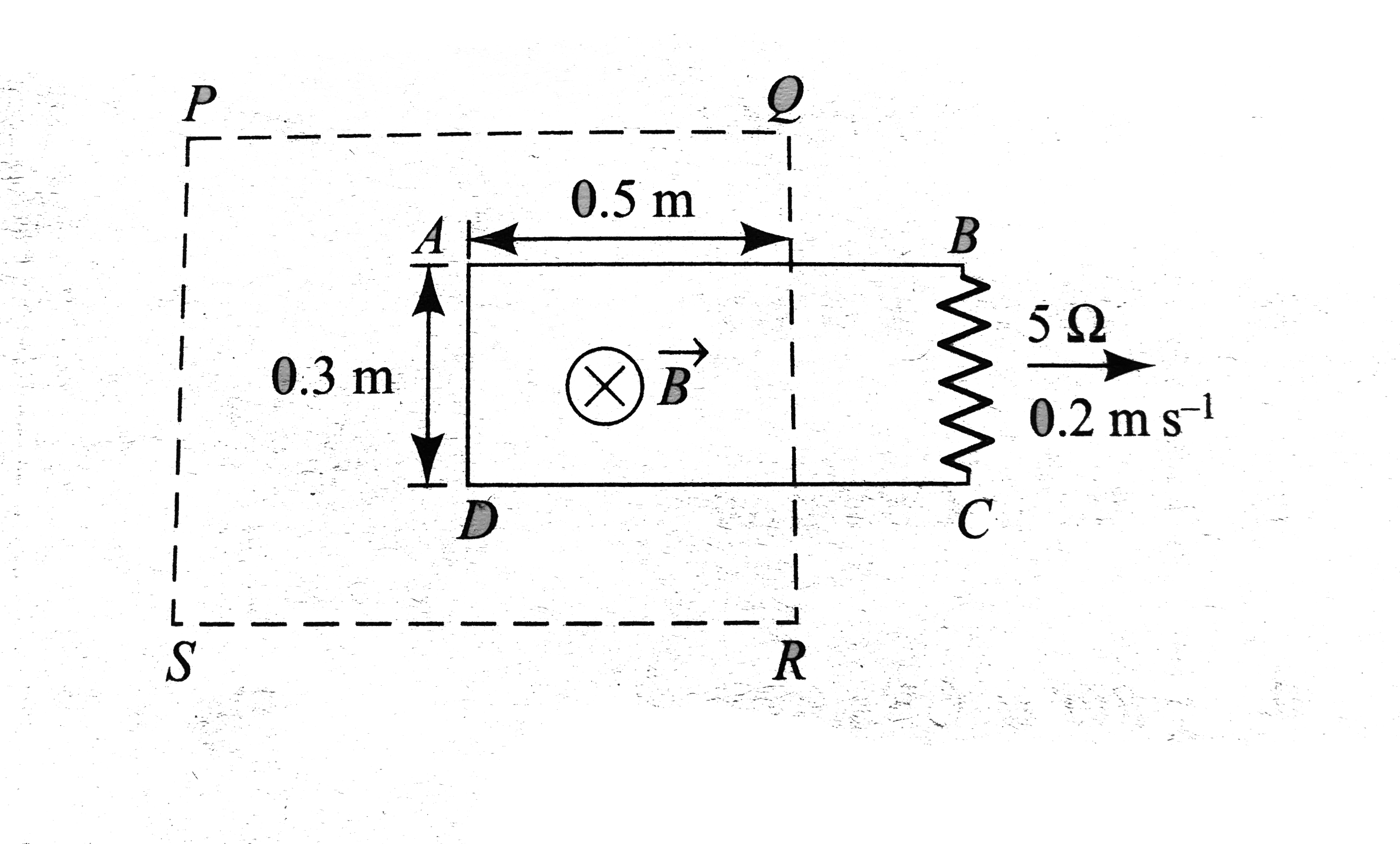
View SolutionA circuit `ABCD` is held perpendicular to the uinform magnetic field of `B = 5 xx 10^(-2)T` extending over the region `PQRS` and directed into the plane of the paper. The cicuit is moving out of the field at a uin form speed of `0.2 m s^(-1)` for `1.5 s`. During this time, the current in the `5 Omega` resistor is
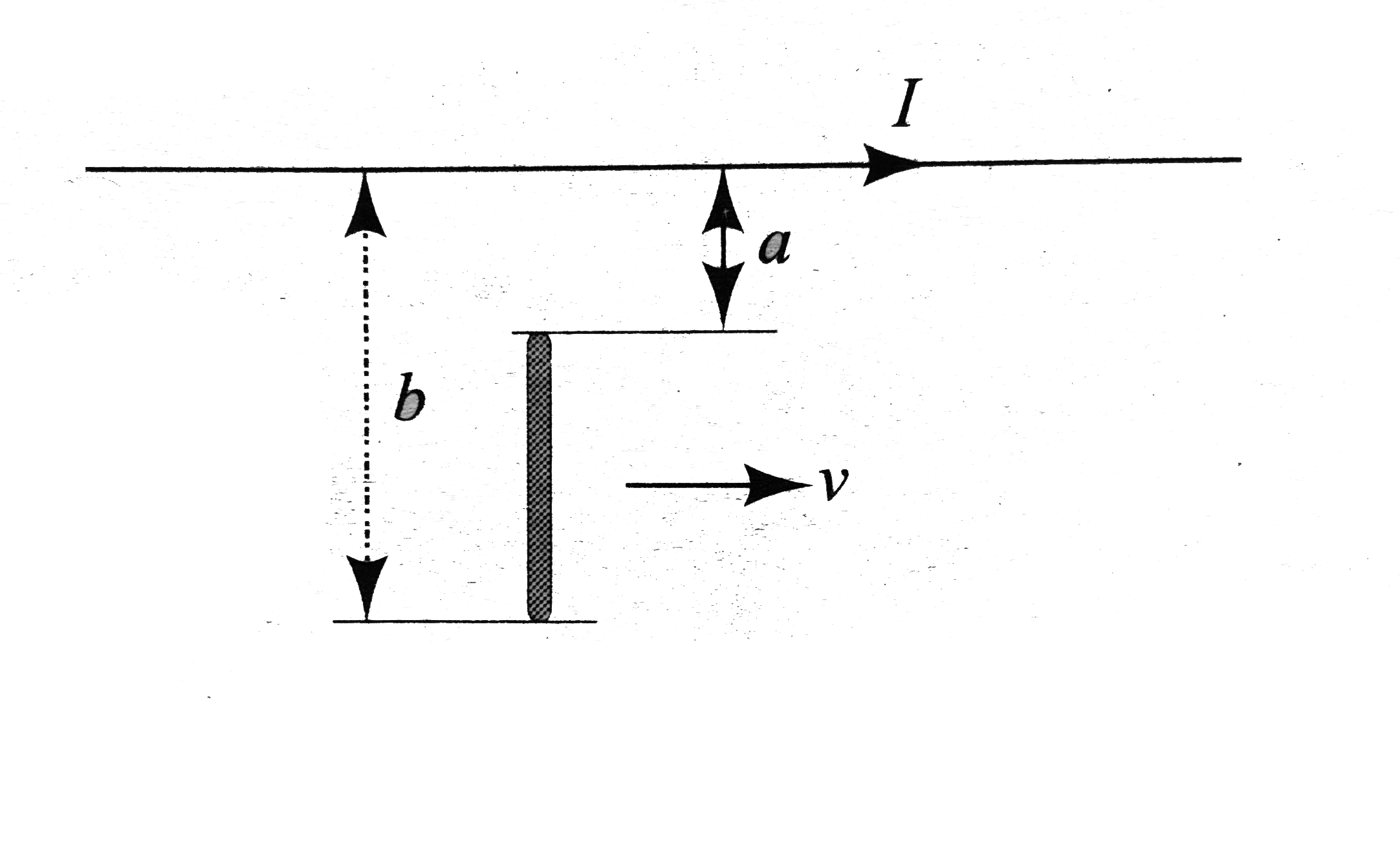
View SolutionShows a copper rod moving with velocity `v` parallel to a long straight wire carrying current `= 100 A`. Calculate the induced emf in the rod, where `v = 5 m S^(-1)`, `a = 1 cm` , `b = 100cm`.
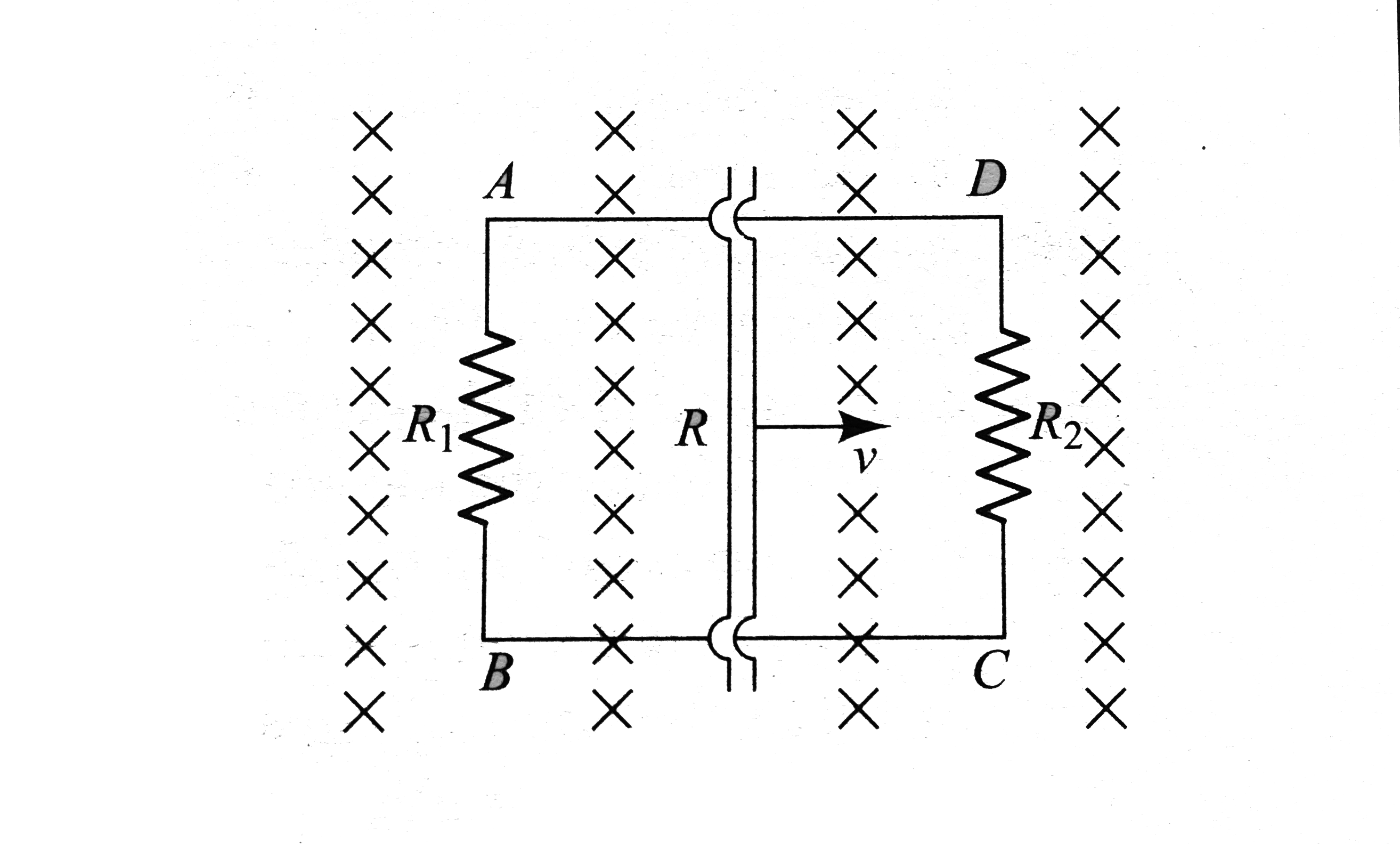
View SolutionA rectangular loop with a sliding conductor of length `l` is located in a uniform magnetic field perpendicular to the plane of the loop . The magneitc inducetion is `b`. The resistances `R_(1)` and `R_(2)`, respectively. Find the current through the conductor during its motion to the right with a constant velocity `v`.
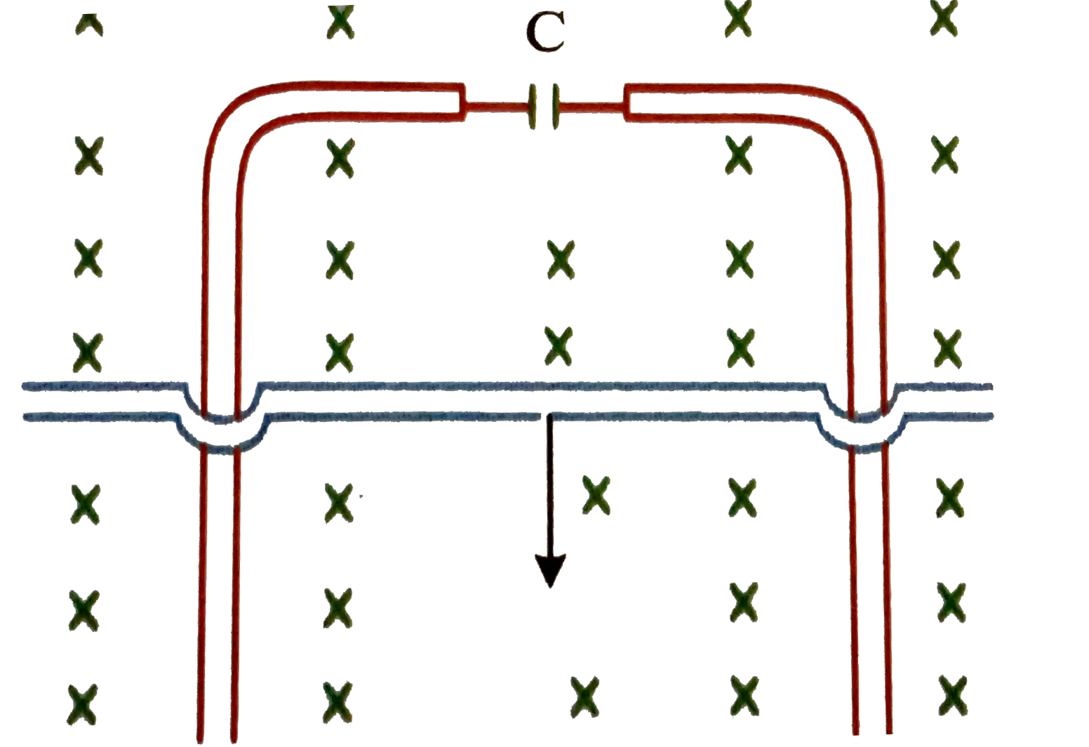
View SolutionA conductor of length `l` and mass `m` can slide without any friction along the two vertical conductors connected at the top through a capacitor. A uniform magnetic field `B` is set up `_|_` to the plane of paper. The acceleration of the conductor
View SolutionA wheel has three spokes and is an uniform magnetic field perpendicular to its plane, with the axis of rotation of the wheel parallel to the magnetic field. When the wheel rotates with a uniform angualr velocity `omega`, the emf induced between the centre and rim of the wheel is `'e'`. If another wheel having same radius but with six spokes is kept in the same field and rotated with a uniform angular velocity `'omega//2'`, the emf induced between the centre and the rim will be
View SolutionA metal rod of length `1m` is rotated about one of its ends in a plane at right angles to a uniform magnetic field pf induction `2.5 xx 10^(-3) Wb m^(-2)`. If it makes `1800` rpm, then the induced emf between its ends approximately is
View SolutionA bicycle si resting on its stand in the east-west direction and rear wheel is rotating at `100` revolution per minute. Length of each spoke is `30 cm`, and vertical component of earth's magnetism is `1.5 xx 10^(-5)` tesla. If the emf induced in the spokes is `3 pi xx 10^(-6)V`, the angle of dip will be :
View SolutionFind the linear speed the bicycle required to power its head light by a generator, whose rubber shaft presses against the wheel of cycle of radius `0.33 m`, turns at an angular speed of `44` times as great as the angular speed of the tire itself. The coil consists of `75` turns, has an area of `2.6 xx 10^(-3) m^(2)`, and rotates in a `0.10 T` magnetic field. When the peak emf being generated is `6.0 V`.
View SolutionThe coil of an ac generator rotates at a frequency of `60 Hz` and develops an induced emf of `120 V (rms)`. The coil has an area of `3.0 xx 10^(-3) m^(2)` and consists of `500` turns. The magnitude of the magnetic field in which the coil rotates is
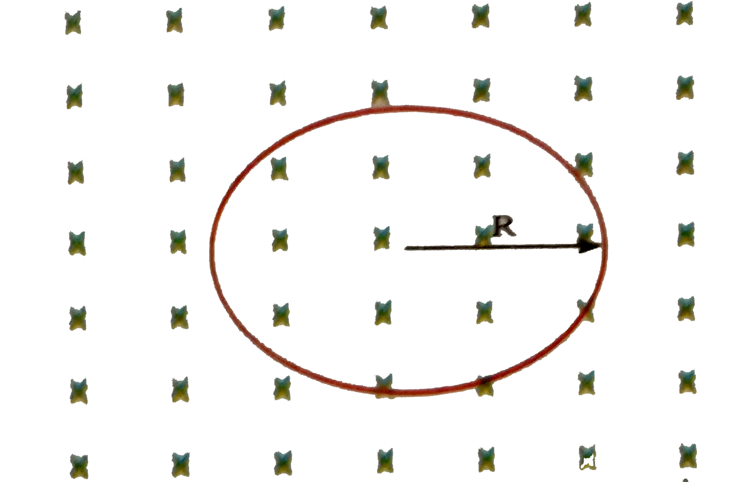
View SolutionA conducting loop of radius `R` is present in a uniform magnetic field `B` perpendicular to the plane of ring. If radius `R` varies as a function of time `t` as `R = R_(0)+t^(2)`. The emf induced in the loop is
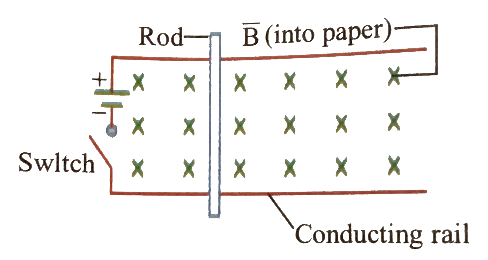
View SolutionA conducting rod is free to slide along a pair of conducting rails, in a region where a uniform and constant (in time) magnetic field is directed into the plane of the paper, as the drawing illustrates. Initially the rod is at rest. There is no frictio between the rails and the rod. What happens to the rod after the switch is closed? If any induced emf devlops, be sure to account for its effect.
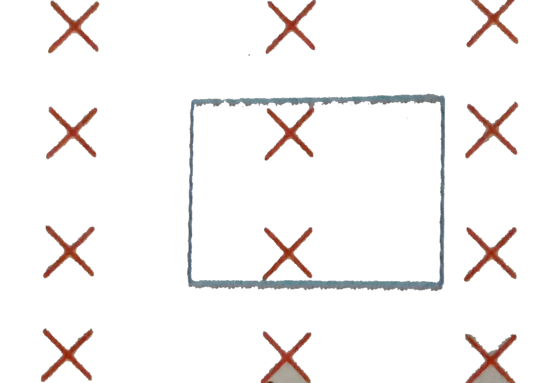
View SolutionA specially uniform magnetic field of `0.080 T` is directed inot the plane of the page and perpendicular to it, as shown in the accompanying figure. A wire loop in the plane of the page has constant area `0.010 m^(2)`. The magnitude of the magnetic field decreases at a constant rate of `3.0 xx 10^(-4) T//s`. The magnitude and direction of the induced emf is
View SolutionA magnetic field induction is changing in magnitude in a region at a constant rate `dB//dt`. A given mass `m` of copper drawn into a wire and formed into a loop is placed perpendicular to the field. If the values of specific resistance and density of copper are `rho` and `sigma` respectively, then the current in the loop is given by :
View SolutionA magnetic flux through a stationary loop with a resistance `R` varies during the time interval `tau` as `phi=at(tau-t)`. Find the amount of the generated in the loop during that time
View SolutionA wire is bent to form the double loop shown in figure. There is a uniform magnetic field directed into the plane of the loop. If the magnitude of this field is decreasing current will flow from:
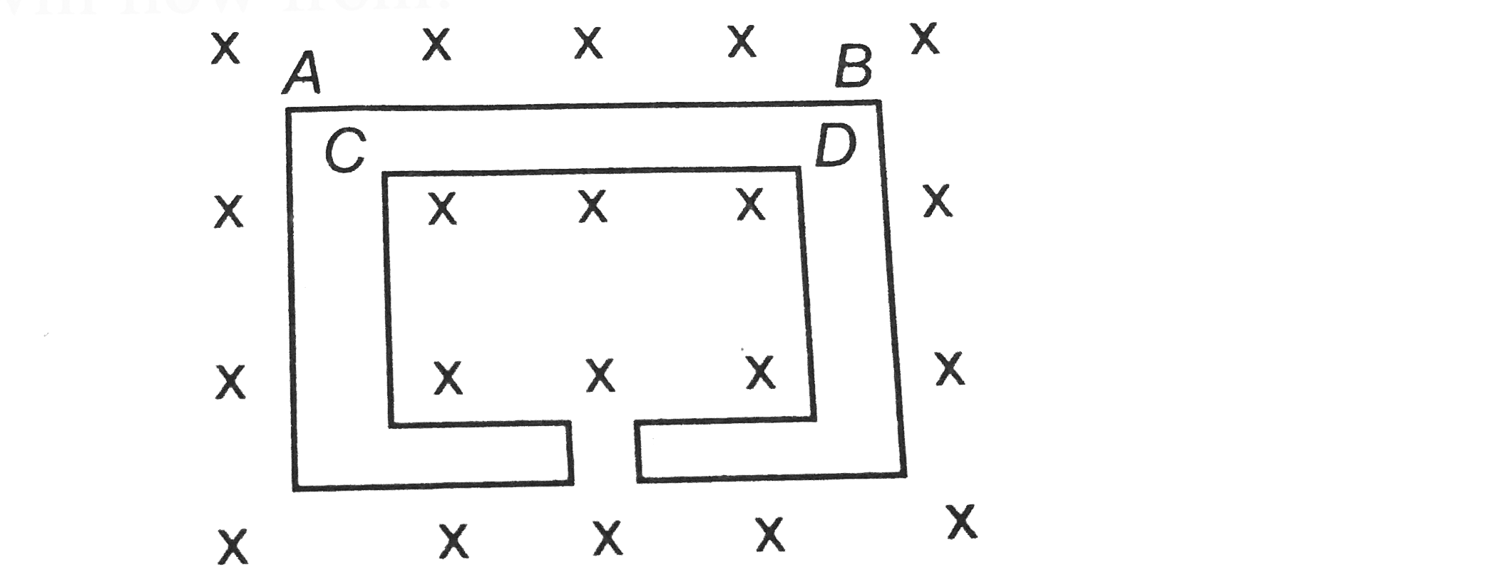
View SolutionTwo coils have self-inductance `L_(1) = 4mH` and `L_(2) = 1 mH` respectively. The currents in the two coils are increased at the same rate. At a certain instant of time both coils are given the same power. If `I_(1)` and `I_(2)` are the currents in the two coils, at that instant of time respectively, then the value of `(I_(1)//I_(2))` is :
View SolutionThe length of a wire required to manufacture a solenoid of length `l` and self-induction `L` is (cross-sectional area is negligible)`
View SolutionThe inductance `L` of a solenoid of length `l`, whose windings are made of material of density `D` and resistivity `rho`, is (the winding resistance is`R`)
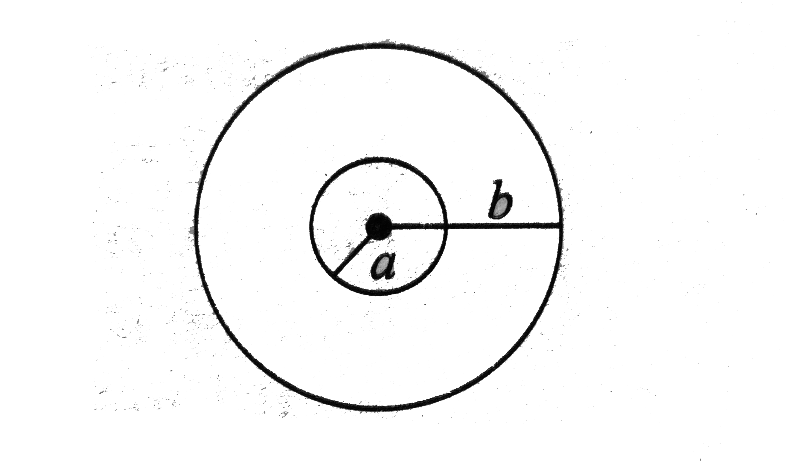
View SolutionTwo concentric and coplanar coils have radii a and `b ( gt gt a)` as shows in Fig. Resistance of the inner coil is `R`. Current in the outer coil is increased from `0` to `i`, then the total charge circulating the inner coil is
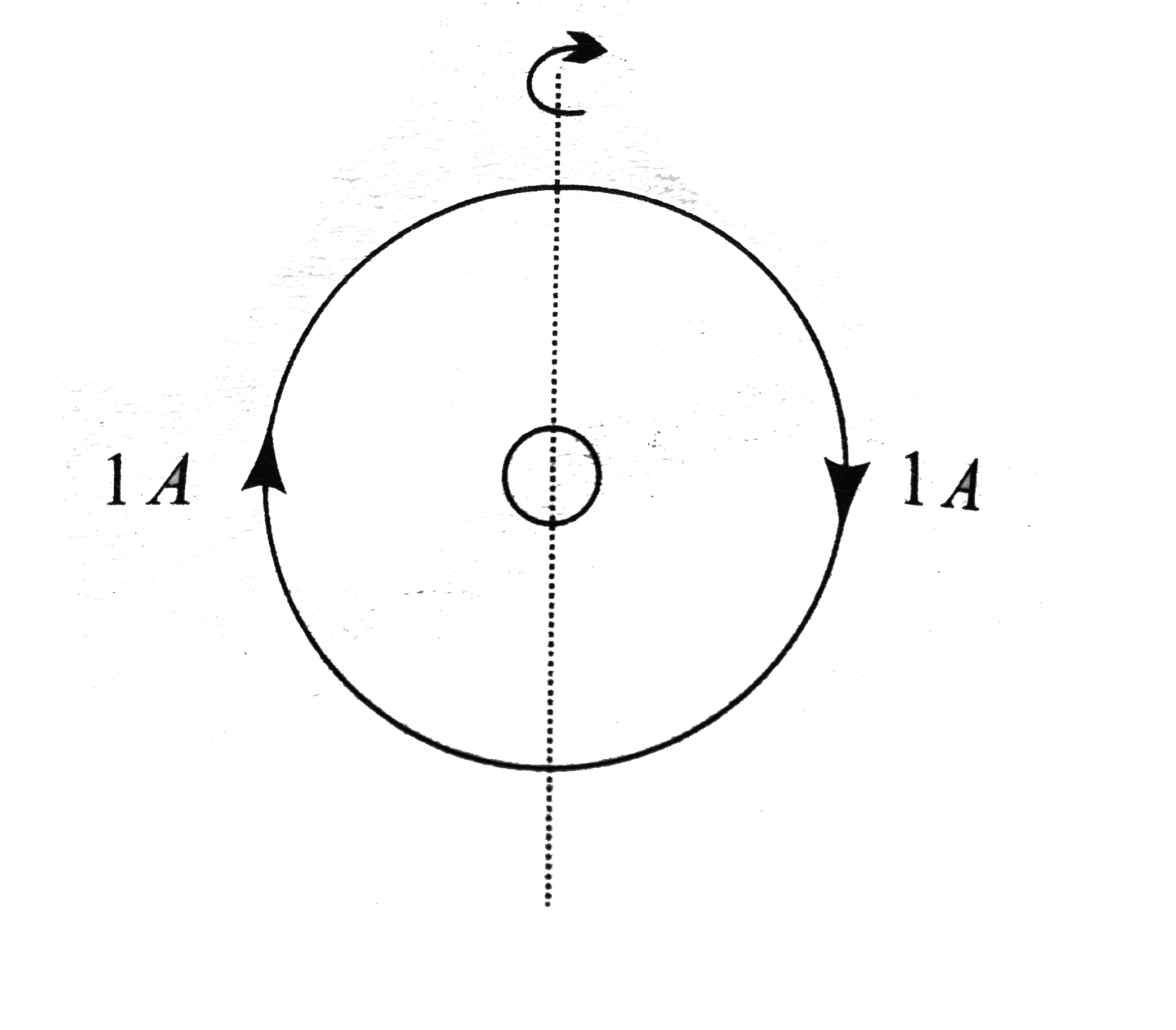
View SolutionThe linear loop has an area of `5 xx 10^(-4)m^(2)` and a resistance oof `2 Omega`. The larger circular loop is fixed and has a radius of `0.1m`. Both the loops are concentric and coplanner. The smaller loop is rotated with an angular velocity `omegarads^(-1)` about its dismeter. The magnetic flux with the smaller loop is
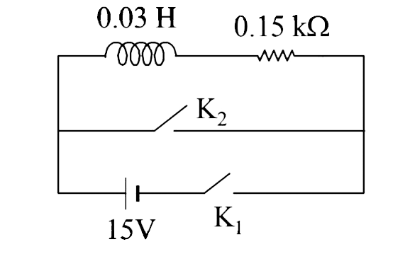
View SolutionAn inductor (L =0.03 H) and a resistor `(R = 0.15k(Omega))` are connected in series to a battery of 15 V EMF in a circuit shown below. The key `K_(1)` is opened and Key `K_(2)` is closed simultaneously. At t =1 ms, the current in the circuit will be `(e^(5) = 150)`
View SolutionA coil of some internal resistance `'r'` behaves line an inductance. When it is connected in series with a resistance `R_(1)`, the time constant is found to be `tau_(1)`. When it is connected in series with a resistance `R_(2)`, the time constant is found to be `tau_(2)`. The inductance of the coil is
View SolutionAn inductance `L` and and a resistance `R` are connected in series to a battery of voltage `V` and negligible internal resistance through a switch. The switch is closed at `t = 0`. The charge that passes through the battery in one time constant is [`e` is base of natural logarithms]
View SolutionA coil of inductance `300mh` and resistance `2Omega` is connected to a source of voltage `2V`. The current reaches half of its steady state value in
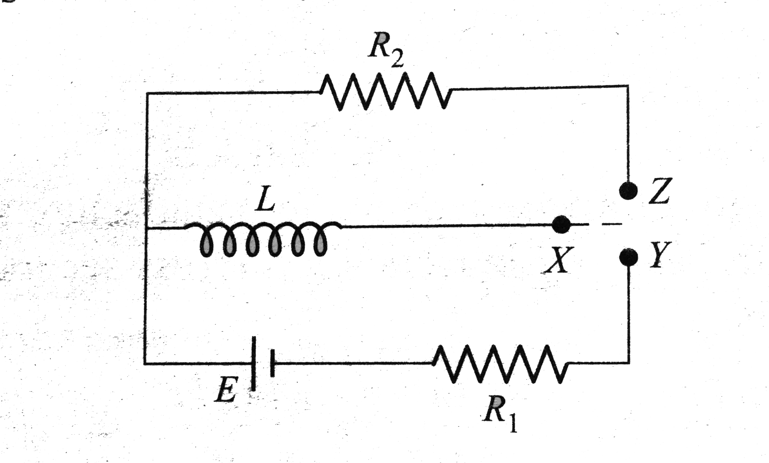
View SolutionIn the current shown Fig., `X` is joined to `Y` for a long time and then `X` is joined to `Z`. The total heat produced in `R_(2)` is
View SolutionA condenser in series with a resistor is connected through a switch to a battery of negligible internal resistance and having an emf of `12 V`. One second after closing the switch, the condenser is found to have a potential difference of `6V`. The time constant of the system is
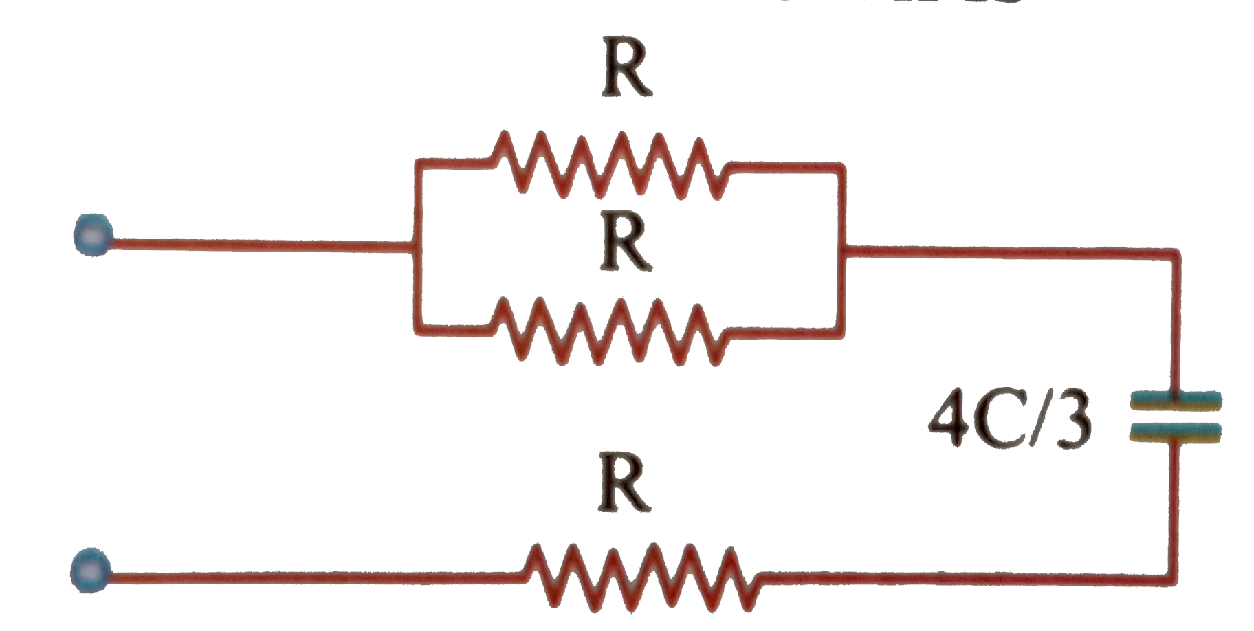
View SolutionThe time constant of the circuit shown is
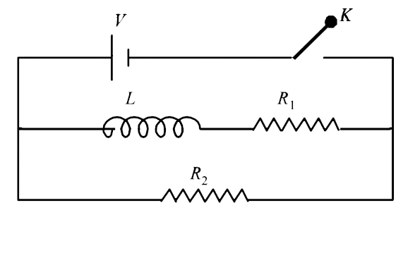
View SolutionIn the circuit shown below, the key K is closed at t =0. The current through the battery is
View SolutionAn equilateral triangular loop `ADC` having some resistance is pulled with a constant velocity `v` out of a uniform magnetic field directed inot the paper. At time `t = 0`, side `DC` of the loop at is at edge of the magnetic field.
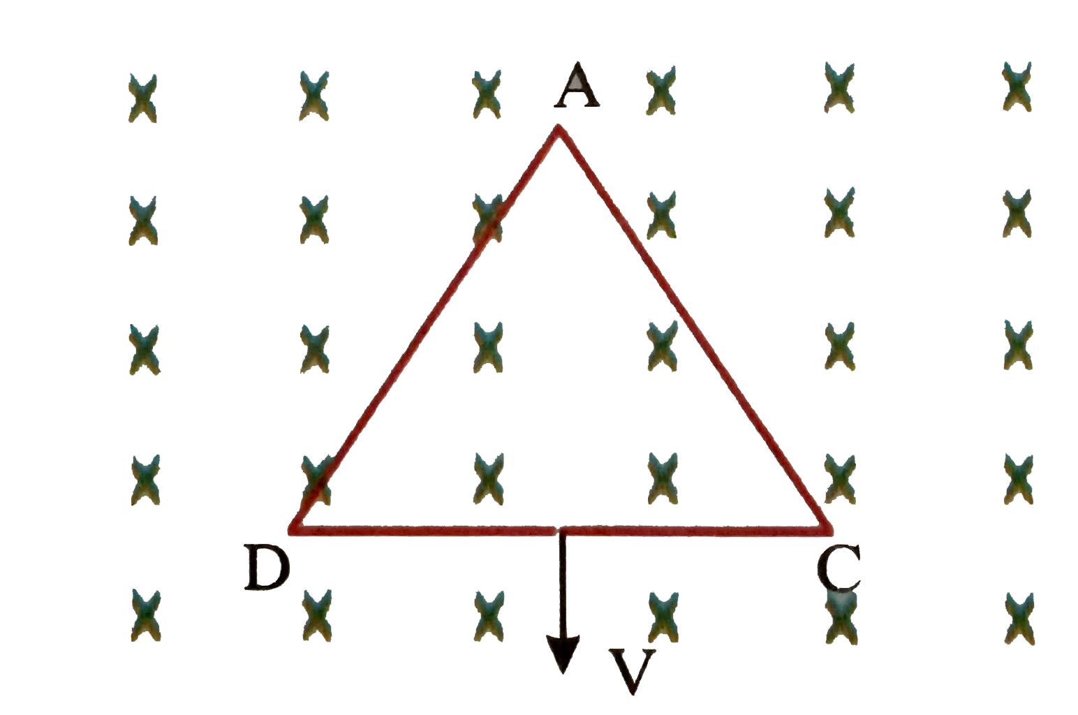
The induced current `(i)` versus time `(t)` graph will be as
View SolutionThe current through the coil in figure (i) varies as shown in figure (ii). Which graph best shows the ammeter `A` reading as a function of time?

View SolutionSwitch `S` of the circuit shows in Fig. is closed at `t = 0`. If `e` denotes the induced emf in `L` and `i` the current flowing through the circuit at time `t`, then which of the following graphs correctly represents the variation of `e` with `i`?
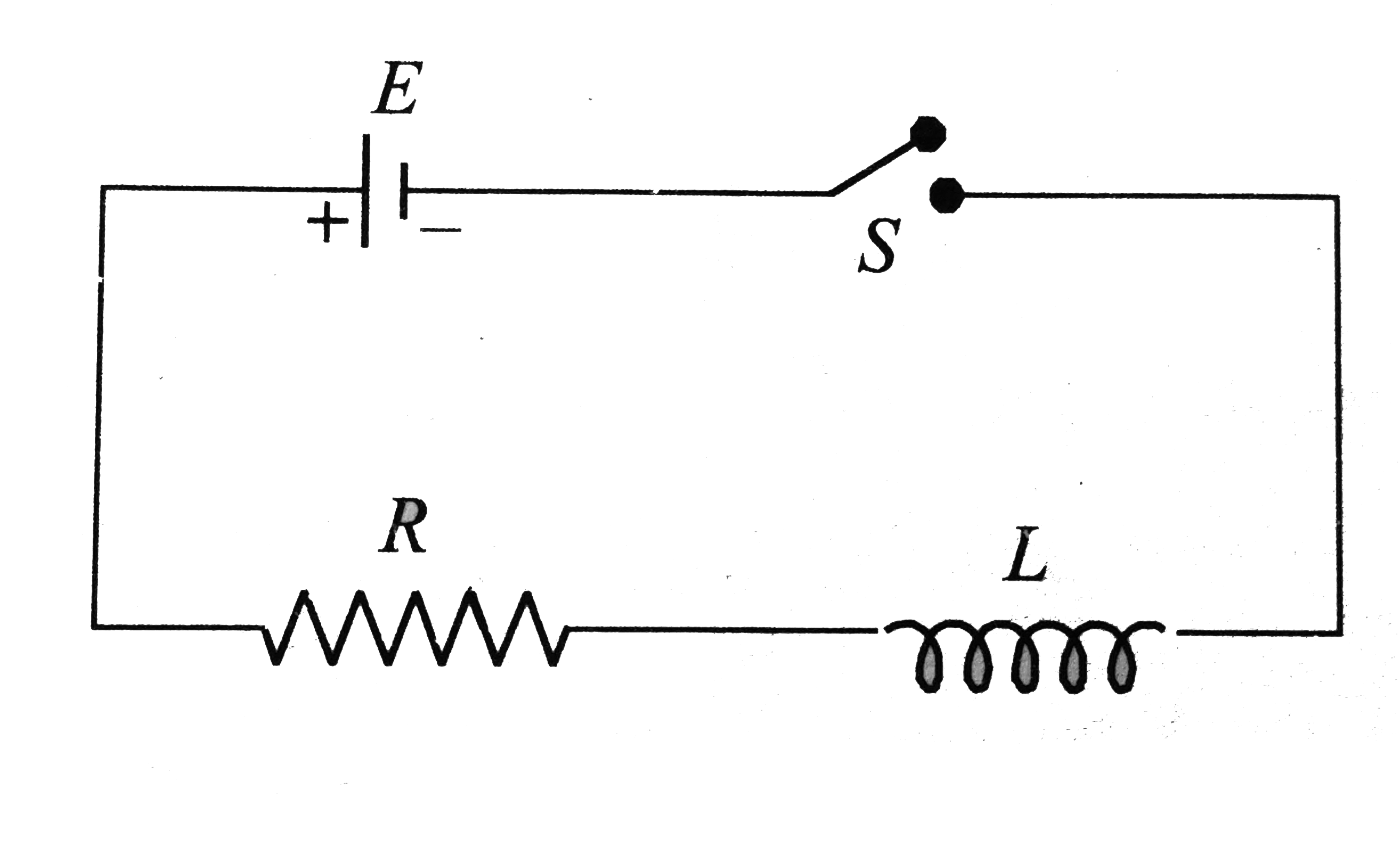
View SolutionSwitch `S` of the circuit shows in Fig is closed at `t = 0`. If `e` denotes the induced emf in `L` and `I` is the current flowing through the circuit at time `t`, which of the following graphs is//are correct?

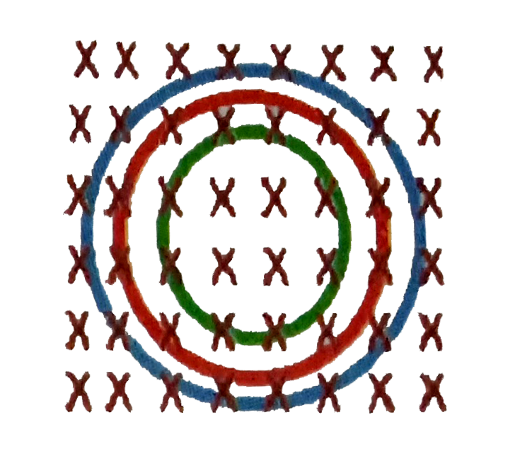
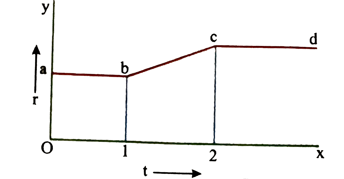
View SolutionA flexible conducting wire in the form of a circle is kept in a uniform magnetic field with its plane normal to the field. Radius of that circle changes with time as shown. Then which of the following graphs represents the variation of induction emf with time `R = R_(0), t lt t_(0) , R = R_(0) + t, t_(0) lt t lt 2t_(0)`:
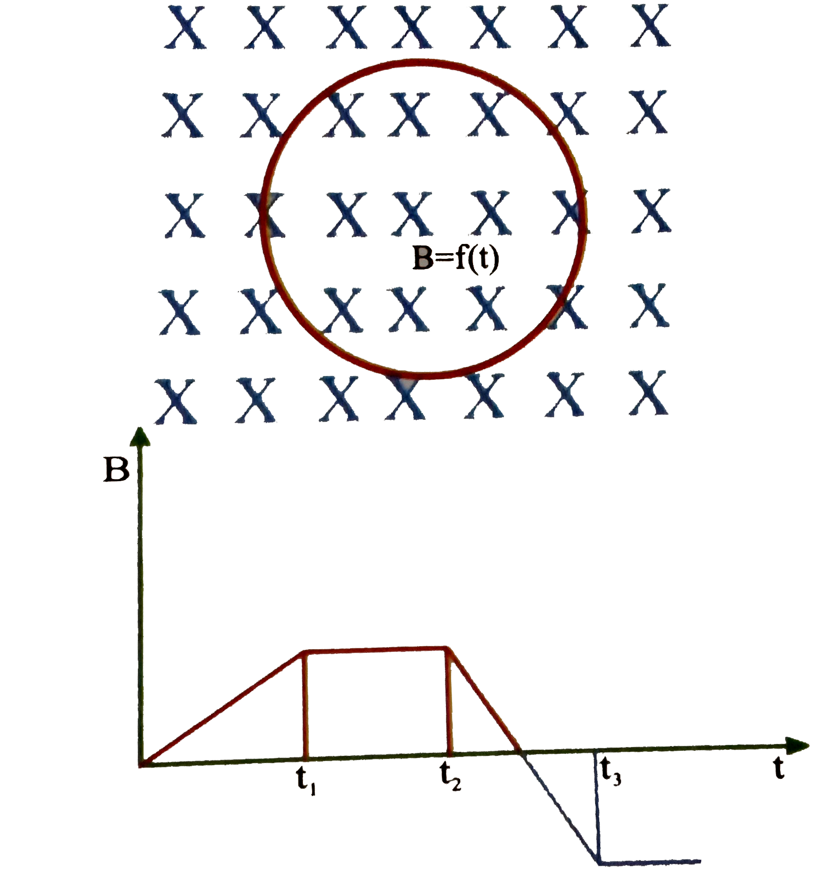
View SolutionA wire loop is placed in a region of time varying magnetic field which oriented orthogonally to the plane of the loop as shown in figure. The graph shows the magnetic field variation as the function of time. Assume the positive emf is the ine which drives a current in the clockwise direction and seen by the observer in the direction of `B`. Which of the following graphs best represents the induced emf a function of time.
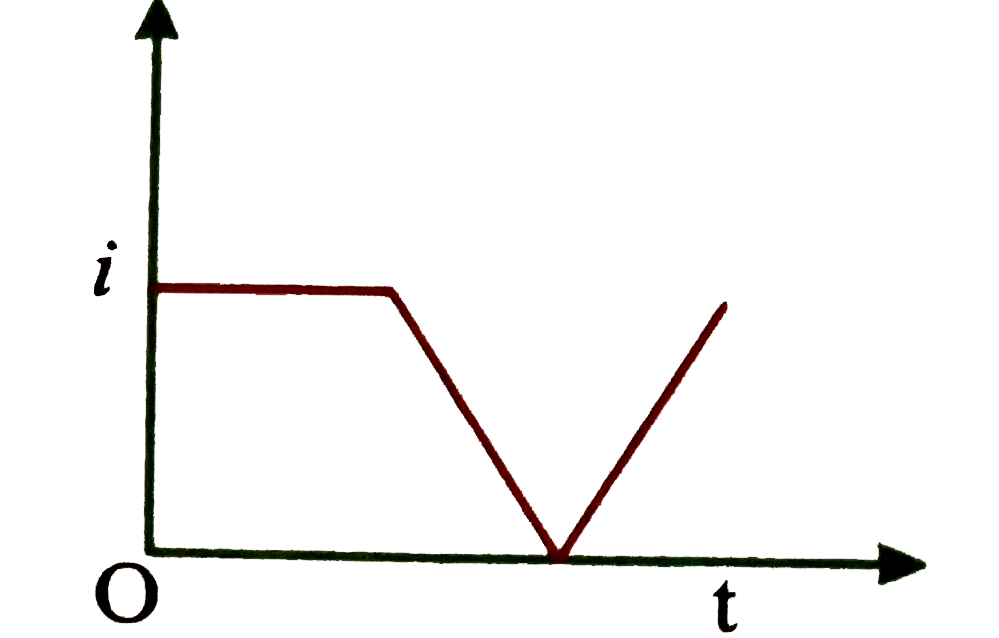
View SolutionThe current is an induction coil varies with time `t`, according to the graph shown in figure. Which of the following graphs shows the induced emf `(e)` in the coil with time.
View SolutionA flexible wire bent in the form of a circle is place in a uniform magnetic field perpendicularly to the plane of the coil. The radius of the coil changes as shown in Figure. The graph of magnetude of induced emf in the coil is represented by
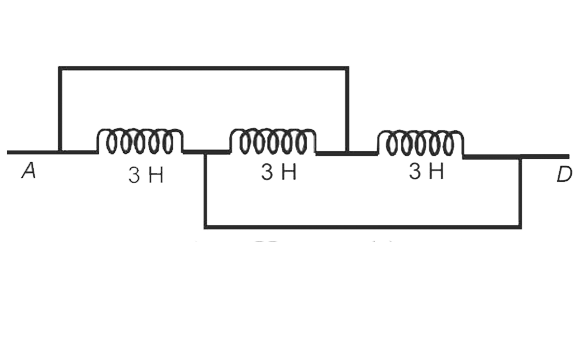
View SolutionThe inductance between A and D is
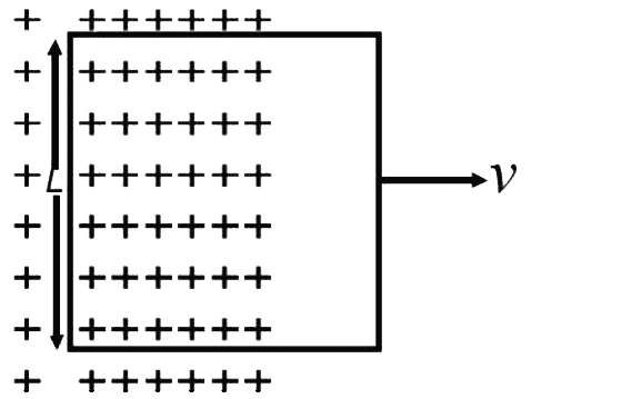
View SolutionA conduting square loop of side L and resistnce R moves in its plane with a uniform velocity v perpendicular to one of its sides. A magnitude induction B constant in time and space, pointing perpendicular and into to plane at the loop exists every with half the loop outside the field, as shown in figure. The induced emf is
View SolutionTwo coil are placed close to each other. The mutual inductance of the pair of coils depends upon.
View SolutionWhen the current changes from `+2A` to `-2A` in `0.05s`, and emf of `8B` is induced in a coil. The coefficient of self-induction of the coil is
View SolutionIn an oscillating LC circuit the maximum charge on the capacitor is Q. The charges on the capacitor when the energy is stored equally between the electric and magnetic field is
View SolutionA coil having n turns and resistance `R Omega` is connected with a galvanometer of resistance `4R Omega`. This combination is moved in time t seconds from a magnetic field `W_(1)` weber to `W_(2)` weber. The induced current in the circuit is
View SolutionIn a uniform magneitc field of induced B a wire in the form of a semicircle of radius r rotates about the diameter of hte circle with an angular frequency `omega`. The axis of rotation is perpendicular to hte field. If the total resistance of hte circuit is R, the mean power generated per period of rotation is
View SolutionA metal conductor of length 1m rotates vertically about one of its ends at angular velocity 5 radians per second. If the horizontal component of earth's magnetic field is `0.2xx10^(-4)T`, then the emf developed between the two ends of hte conductor is
View Solutionin a LCR circuit capacitance is chagned from C to 2C. For the resomat frequency to remain unchaged, the inductance should be chagned from L to
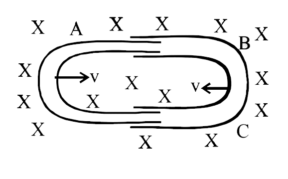
View SolutionOne conducting U tube can slide inside another as shown in figure, maintaining electrical contacts between the tubes. The magnetic field B is perpendicular to the plane of the figure. If each tube maoves towards the other at a constant speed v. Then the emf induced in the circuit in terms of B, l and v where l is the width of each tube will be
View SolutionThe self inductance of the motor of an electric fan is 10H. In order to impart maximum power at 50 Hz, it should be connected to a capacitance of
View SolutionA coil of inductance `300mh` and resistance `2Omega` is connected to a source of voltage `2V`. The current reaches half of its steady state value in
View SolutionAn inductor `(L = 100 mH)`, a resistor `(R = 100 Omega)`, and a battery `(W = 100 V)` are initially connected in series as shown by the figure. After a long time the battery is disconnected after short circuiting the points `A` and `B`. The currents in the circuit `1 mm` after the short circuit is
View SolutionThe flux linked with a coil at any instant 't' is given by `phi = 10t^(2) - 50t +250`
The induced emf at `t = 3s` is
View SolutionAn ideal coil of 10H is connected in series with a resistance of `5(Omega)` and a battery of 5V. 2second after the connections is made, the current flowing in ampere in the circuit is
View SolutionTwo coaxial solenoids are made by winding thin insulated wire over a pipe of cross-sectional area `A=10 cm^(2)` and length =20cm. If one of the solenoid has 300 turns and the other 400 turns, their mutual indcutance is
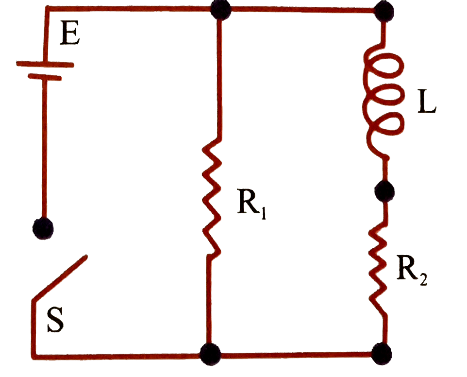
View SolutionAn inductor of inductance L=400 mH and resistor of resistance `R_(1) = 2(Omega) and R_(2) = 2 (Omega)` are connected to a battery of emf E = 12 Vas shown in the figure. The internal resistance of the battery is negligible. The switch S is closed at time t =0. What is the potential drop across L as a function of time? After the steady state is reached, the switch is opened. What is the direction and the magnitude of current through `R_(1)` as a function of time?
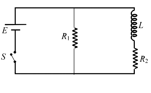
View SolutionIn the circuit shown below, the key K is closed at t =0. The current through the battery is

View SolutionA fully charged capacitor C with initial charge `q_(0)` is connected to a coil of self inductance L at t=0. The time at which the energy is stored equally between the electric and the magnetic fields is
View SolutionA boat is moving due east in a region where the earth's magnetic field is `5.0xx10^(-5) NA^(-1)m^(-1)` due north and horizontal. The boat carries a vertical aerial 2 m long. If the speed of the boat is `1.50 ms^(-1)`, the magnitude of the induced emf in the wire of aerial is
View SolutionA coil is suspended in a uniform magnetic field, with the plane of the coil parallel to the magnetic lines of force. When a current is passed through the coil it starts oscillating, It is very difficult to stop. But if an aluminium plate is placed near to the coil, it stops. This is due to :
View SolutionA metallic rod of length 'l' is tied to a string of length 2l and made to rotate with angular speed w on a horizontal table with one end of the string fixed. If there is a vertical magnetic field 'B' in the region, the e.m.f. Induced across the ends of the rod is
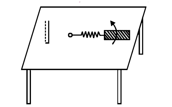
View SolutionA circular loop of radius 0.3 cm lies parallel to amuch bigger circular loop of radius 20 cm. The centre of the small loop is on the axis of the bigger loop. The distance between their centres is 15 cm. If a current of 2.0 A flows through the smaller loop, then the flux linked with bigger loop is
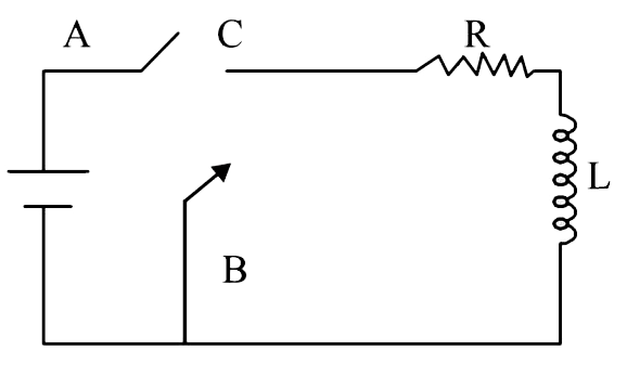
View SolutionIn the circuit shown here, the point 'C' is kept connected to point 'A' till the current flowing through the circuit becomes constant. Afterward, suddenly, point 'C' is disconnected from point 'A' an connected to point 'B' at time t =0. Ratio of the voltage across resistance and the inductor at `t =L//R` will be equal to:
View SolutionAn LCR curcuit is equivalent to a damped pendulum. In an LCR circuit the capacitor is charged to `(Q_0)` and then connected to the L ans R as shown below.
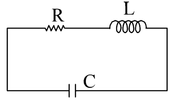
If a student plaots graphs of the square of maximum charge `(Q_(max)^(2))` on the capacitor with time (t) for two different values `L_(1) and L_(2) (L_(1)gtL_(2))` of L then which of the following represents this graph correclty? (plots are schematic and not drawn to scale).
View Solution
Level - III questions and complete solutions for chapter ELECTRO MAGNETIC INDUCTION of NARAYANA PHYSICS (HINGLISH) of Class 12