Complete Solutions to Comprehension Type Questions of chapter ELECTRO MAGNETIC INDUCTION of Class 12 book with complete answers and questions
| Class 12 | PHYSICS |
| Chapter | ELECTRO MAGNETIC INDUCTION |
| NARAYANA | Comprehension Type Questions |
| Number Of Questions | 22 |
| Academic Year | 2023-24 |
A conductor of mass `m` and length `l` is sliding smoothly an two vertical conducting rails `AB` and `CD` as shown in figure. The top ends of two conducting rails are joined by a capacitor of capacitance `C`. The conductor is relased from rest when it is very close to `AC` i.e., `y = 0`. A uniform magnetic field `B_(0)` perpendicular to plane of figure existing. Neglect the resistance of rails and connecting wires. Take acceleration due to gravity to be `g`.
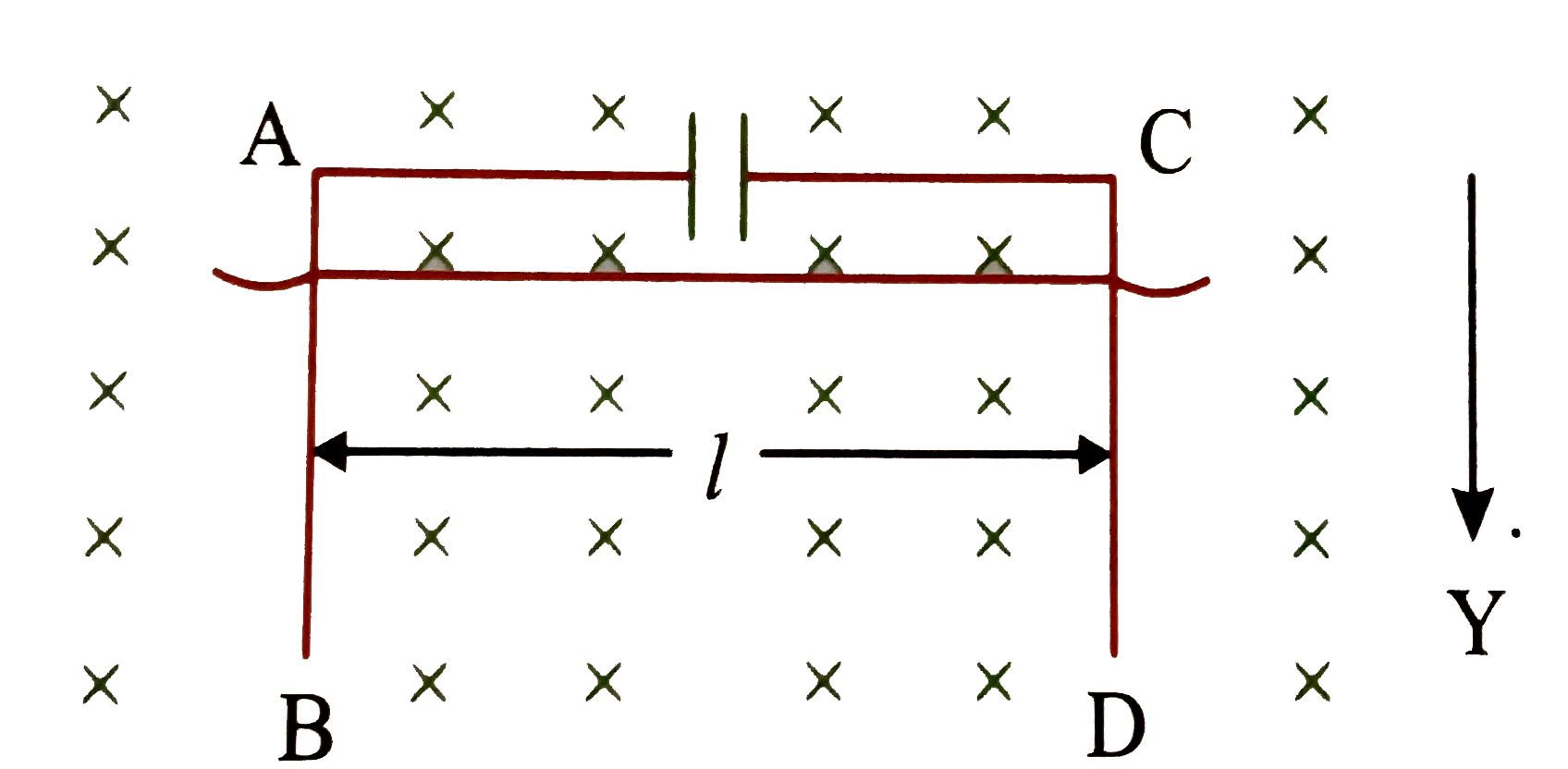
Based on above information answer the following questions:
Mark the correct statement about the motion of conductor
View SolutionA conductor of mass `m` and length `l` is sliding smoothly an two vertical conducting rails `AB` and `CD` as shown in figure. The top ends of two conducting rails are joined by a capacitor of capacitance `C`. The conductor is relased from rest when it is very close to `AC` i.e., `y = 0`. A uniform magnetic field `B_(0)` perpendicular to plane of figure existing. Neglect the resistance of rails and connecting wires. Take acceleration due to gravity to be `g`.
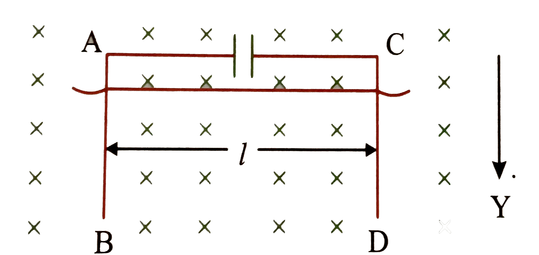
Based on above information answer the following questions:
Charge on the capacitor as a function of distance travelled `y` is given by
View SolutionA conductor of mass `m` and length `l` is sliding smoothly an two vertical conducting rails `AB` and `CD` as shown in figure. The top ends of two conducting rails are joined by a capacitor of capacitance `C`. The conductor is relased from rest when it is very close to `AC` i.e., `y = 0`. A uniform magnetic field `B_(0)` perpendicular to plane of figure existing. Neglect the resistance of rails and connecting wires. Take acceleration due to gravity to be `g`.
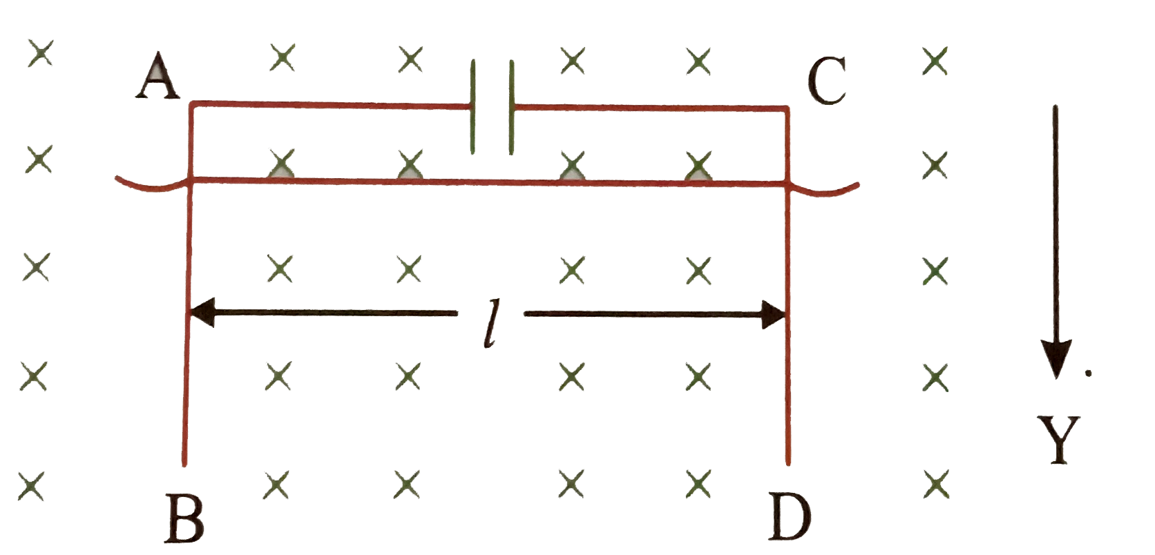
Based on above information answer the following questions:
Current in the circuit is
View SolutionA thin non-conducting ring mass `m`, radius `a`, carrying a charge `q` can rotate freely about its own axis which is vertical. At the initial moment the ring was at rest and no magnetic field was present. At instant `t = 0`, a uniform magnetic field is switched on which is vertically downwards and increase with time according to the law `B = B_(0)t`. Neglecting magnetism induced due to totational motion of the ring. Now answer the following questions.
The angular acceleration of the ring and its direction of rotation as seen from above: if `E` is induced `e.m.f`
View SolutionA thin non-conducting ring mass `m`, radius `a`, carrying a charge `q` can rotate freely about its own axis which is vertical. At the initial moment the ring was at rest and no magnetic field was present. At instant `t = 0`, a uniform magnetic field is switched on which is vertically downwards and increase with time according to the law `B = B_(0)t`. Neglecting magnetism induced due to totational motion of the ring. Now answer the following questions.
The power developed by the forces acting on the ring, as a function of time :
View SolutionTwo capacitors of capacitance `C` and `3C` are charged to potential difference `V_(0)` and `2V_(0)` respectively, and connected to an inductor of inductance `L` as shown in figure. Initially the current in the inductor is zero. Now, the switch `S` is closed.
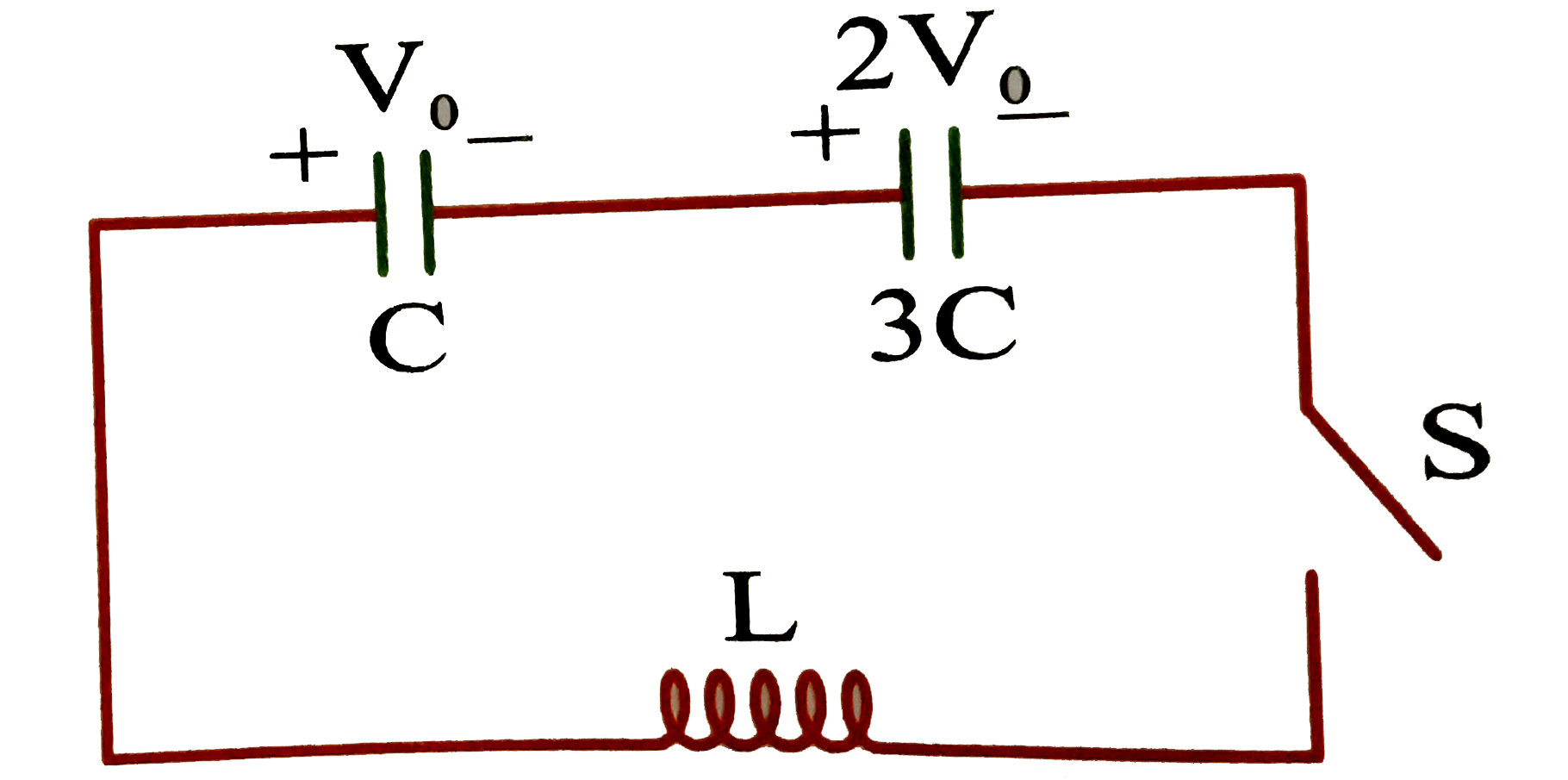
The maximum current in the indcutor is :
View SolutionTwo capacitors of capacitance `C` and `3C` are charged to potential difference `V_(0)` and `2V_(0)` respectively, and connected to an inductor of inductance `L` as shown in figure. Initially the current in the inductor is zero. Now, the switch `S` is closed.
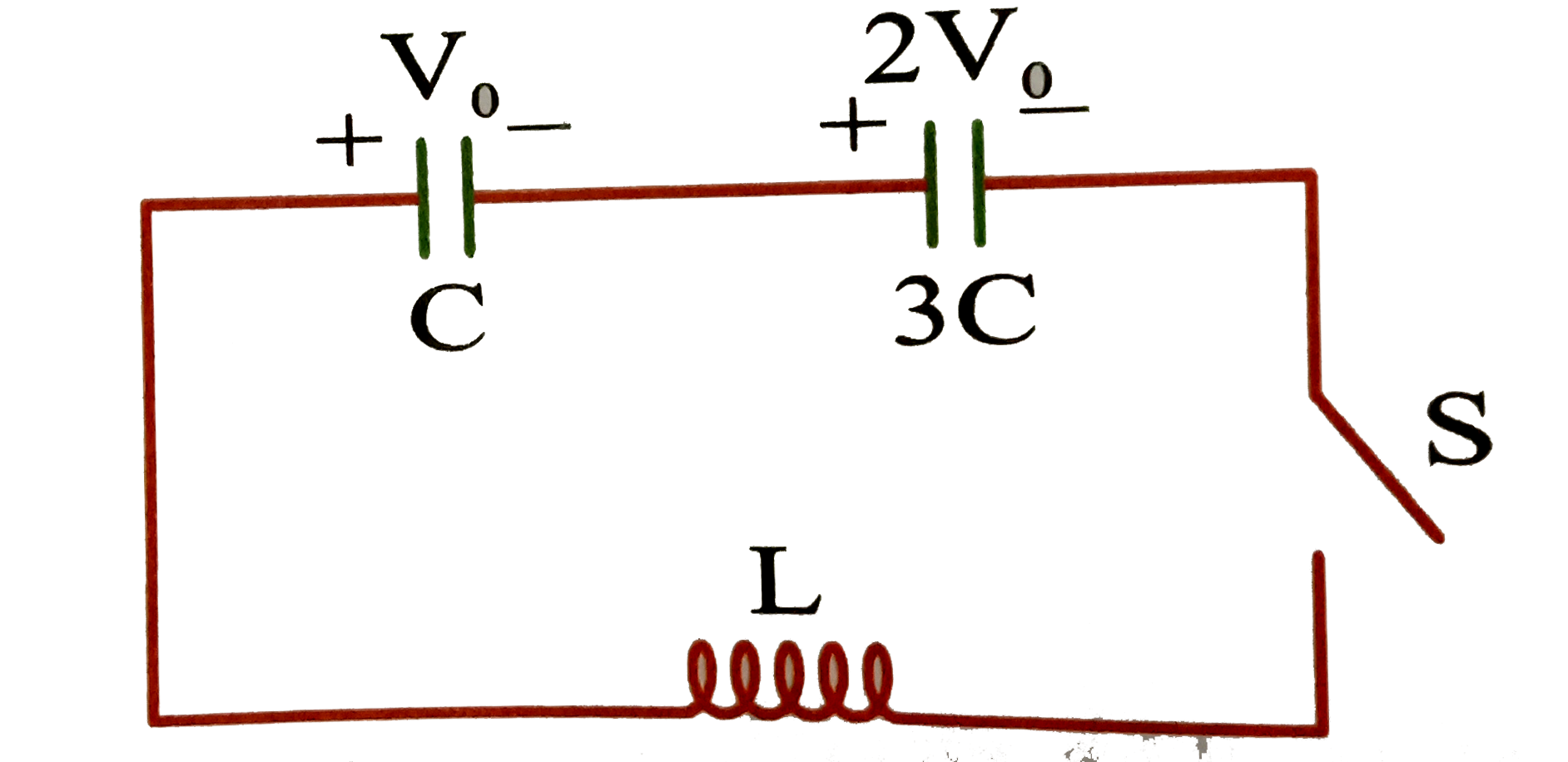
Potential difference across capacitor of capacitance `C` when the current in the cirucit is maximum is
View SolutionTwo capacitors of capacitance `C` and `3C` are charged to potential difference `V_(0)` and `2V_(0)` respectively, and connected to an inductor of inductance `L` as shown in figure. Initially the current in the inductor is zero. Now, the switch `S` is closed.
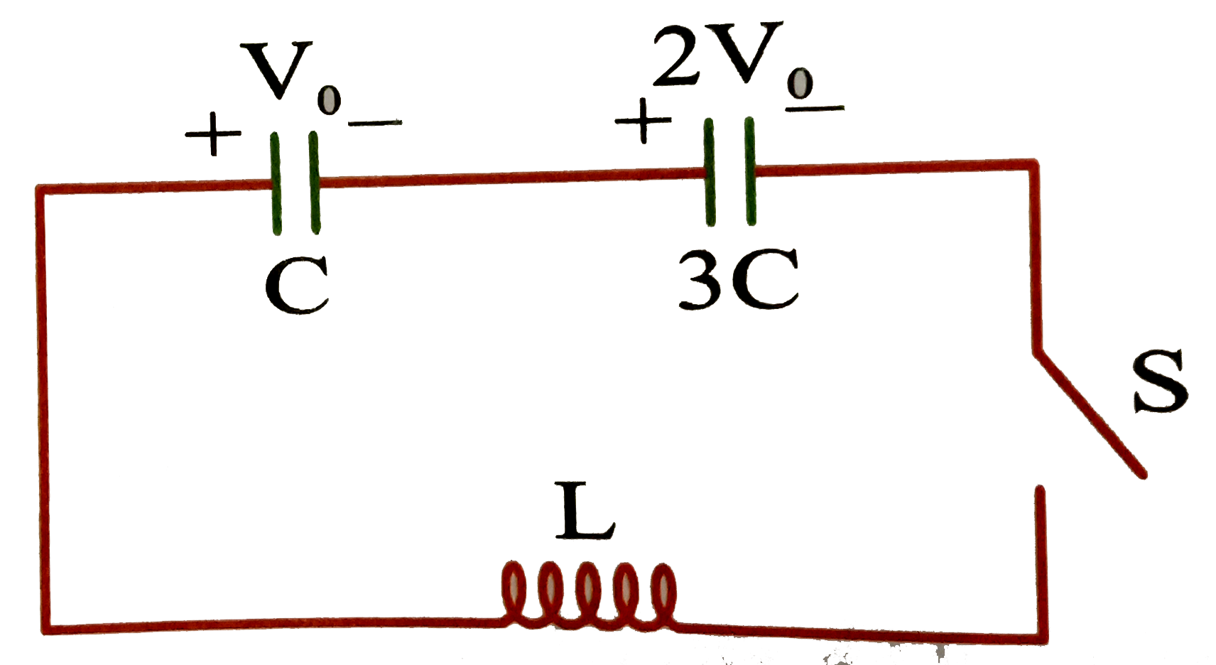
Potential difference across capacitor of capacitance `3C` when the current in the cirucit is maximum is :
View SolutionSwitches `S_(1), S_(2)` remain open and switch `S_(3)` remains closed for long time such that capacitor becomes fully charged and current in inductor coil becomes maximum, Now switches `S_(1), S_(2)` are simultaneously closed and`S_(3)` in simultaneously opened at `t=0`
Assume that battery and inductor coil are ideal
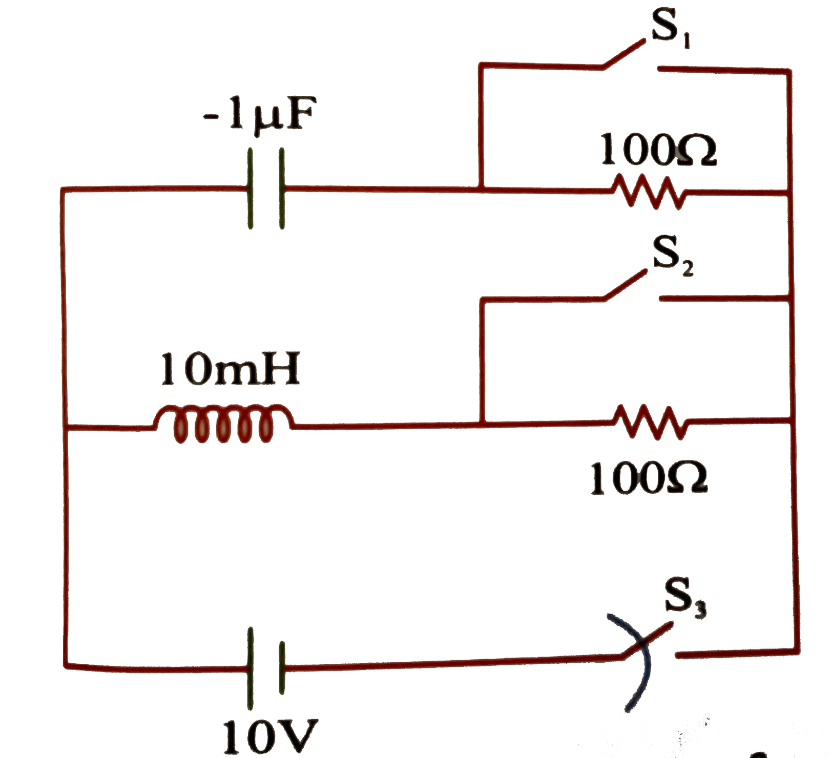
Charge (in `mu C`) on capacitor as a function of time is :
View SolutionSwitches `S_(1), S_(2)` remain open and switch `S_(3)` remains closed for long time such that capacitor becomes fully charged and current in inductor coil becomes maximum, Now switches `S_(1), S_(2)` are simultaneously closed and`S_(3)` in simultaneously opened at `t=0`
Assume that battery and inductor coil are ideal
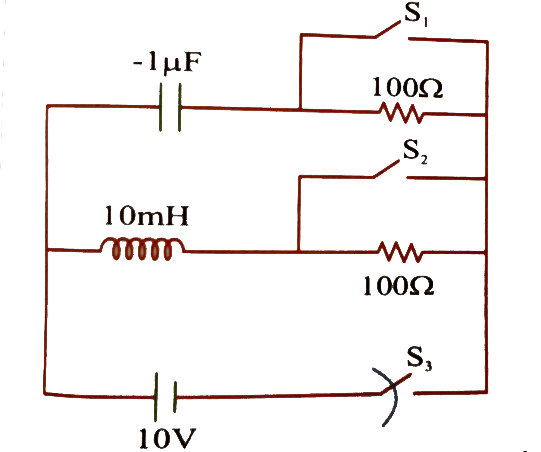
Maximum current in the inductor coil at any times `t gt 0`
View SolutionSwitches `S_(1), S_(2)` remain open and switch `S_(3)` remains closed for long time such that capacitor becomes fully charged and current in inductor coil becomes maximum, Now switches `S_(1), S_(2)` are simultaneously closed and`S_(3)` in simultaneously opened at `t=0`
Assume that battery and inductor coil are ideal
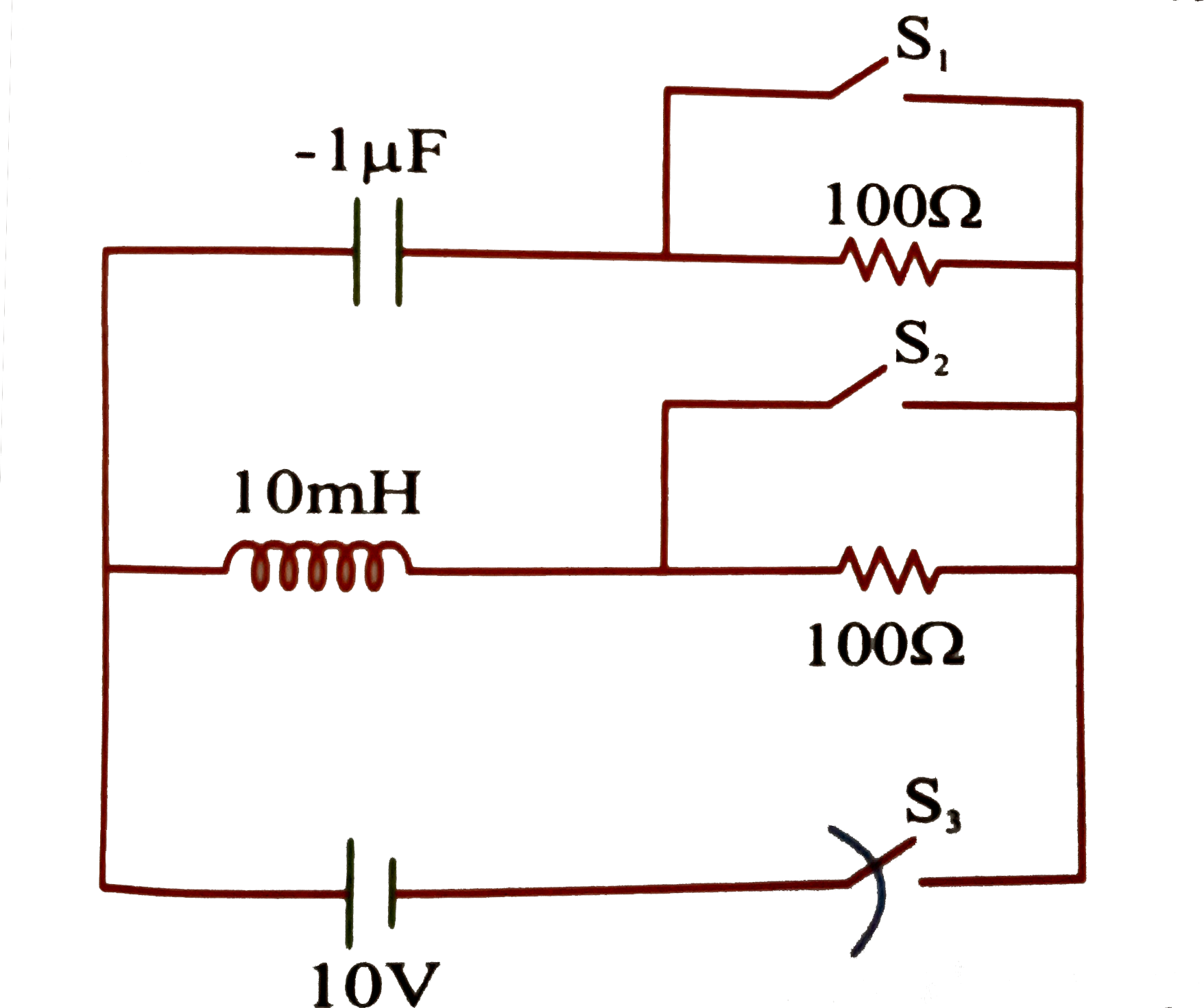
Find time `t gt 0`, when energy store in inductor would have minimum for the first time ?
View SolutionIn the shown figure, there are two long fixed parallel conducting rails (having negligible resistance) and are separated by distance `L`. A uniform rod of resistance `R` and mass `M` is placed at rest on frictionless rails. Now at time `t = 0`, a capacitor having charge `Q_(0)` and capacitance `C` is connected across rails at ends `a` and `b` such that current in rod `(c d)` is from `c` towards `d` and the rod is released. A uniform and constant magnetic field having magnitude `B` exists normal to plane of paper as shown. (Neglect acceleration due to gravity)
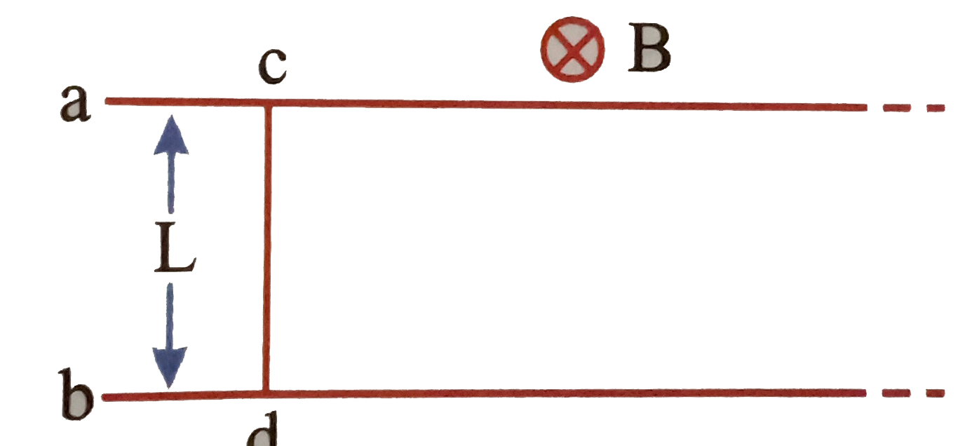
When the speed of rod is `v`, the charge on capacitor is :
View SolutionIn the shown figure, there are two long fixed parallel conducting rails (having negligible resistance) and are separated by distance `L`. A uniform rod of resistance `R` and mass `M` is placed at rest on frictionless rails. Now at time `t = 0`, a capacitor having charge `Q_(0)` and capacitance `C` is connected across rails at ends `a` and `b` such that current in rod `(c d)` is from `c` towards `d` and the rod is released. A uniform and constant magnetic field having magnitude `B` exists normal to plane of paper as shown. (Neglect acceleration due to gravity)
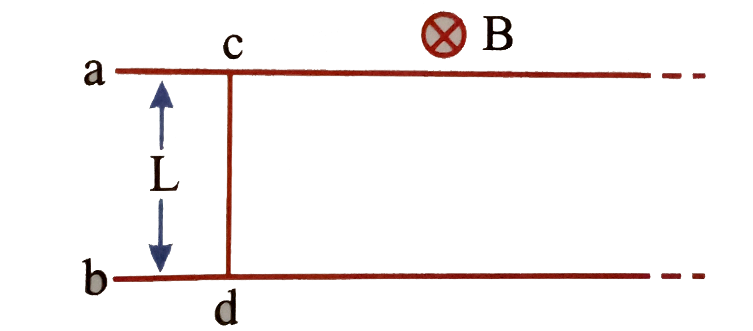
When the acceleration of rod is zero, the speed of rod is :
View SolutionIn the shown figure, there are two long fixed parallel conducting rails (having negligible resistance) and are separated by distance `L`. A uniform rod of resistance `R` and mass `M` is placed at rest on frictionless rails. Now at time `t = 0`, a capacitor having charge `Q_(0)` and capacitance `C` is connected across rails at ends `a` and `b` such that current in rod `(c d)` is from `c` towards `d` and the rod is released. A uniform and constant magnetic field having magnitude `B` exists normal to plane of paper as shown. (Neglect acceleration due to gravity)
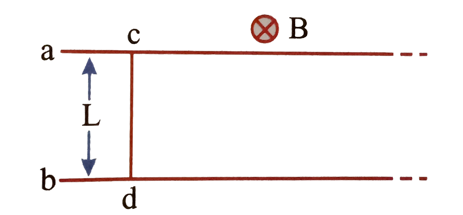
When the acceleration of rod is zero, the charge on capacitor is:
View SolutionSix loops are formed of copper wire of the same cross-sectional area. Loops `1,2,3` and `4` are identical, loop `5` has the same area as the others but is longer. At the instant shown, all the loops are moving at the same speed in the directions indicated. A uniform and constant magnetic field points out of the page in region `I`, in region `II` there is no magnetic field. Ignore any interaction between the loops.
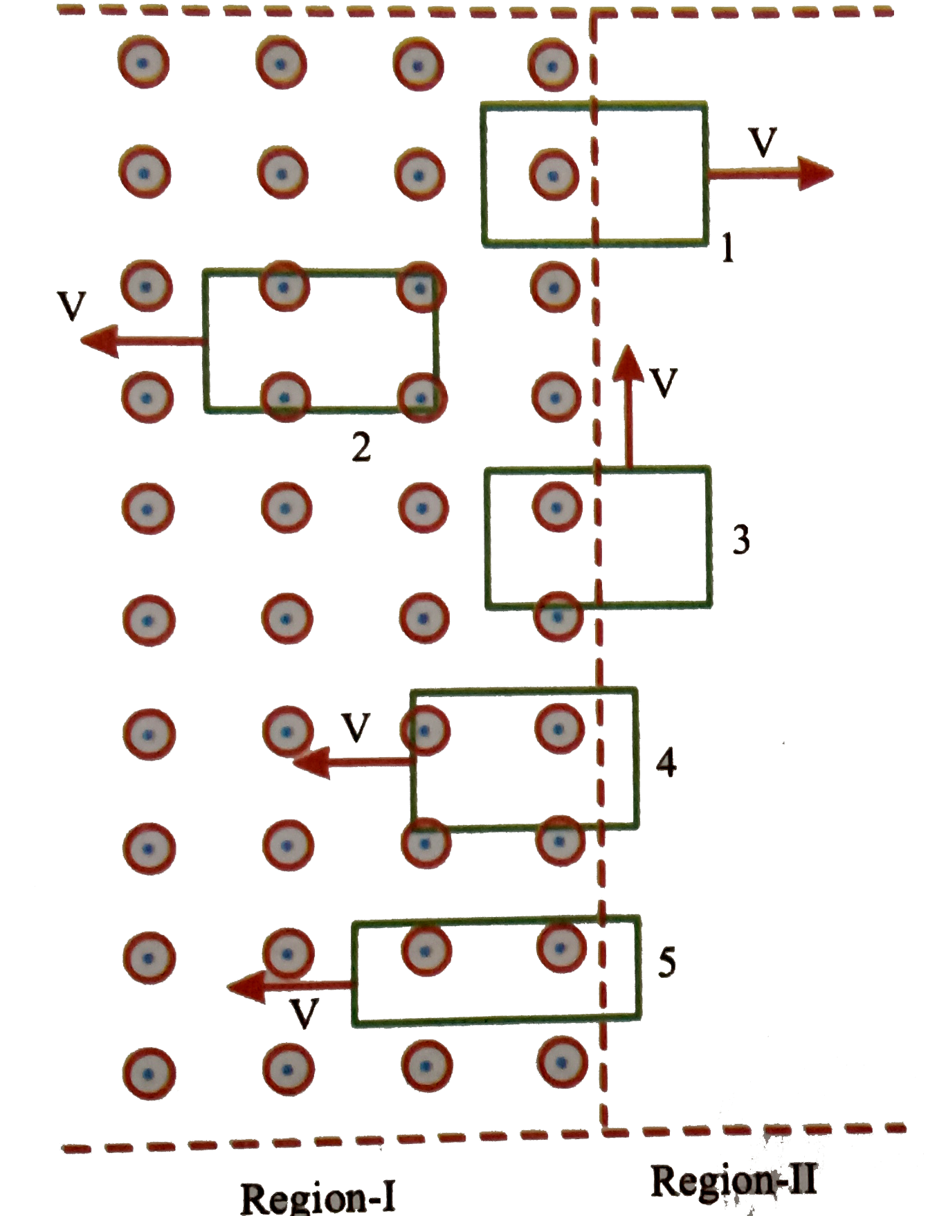
Then the number of loop or loops in which current is nonzero and in clockwise direction
View SolutionSix loops are formed of copper wire of the same cross-sectional area. Loops `1,2,3` and `4` are identical, loop `5` has the same area as the others but is longer. At the instant shown, all the loops are moving at the same speed in the directions indicated. A uniform and constant magnetic field points out of the page in region `I`, in region `II` there is no magnetic field. Ignore any interaction between the loops.
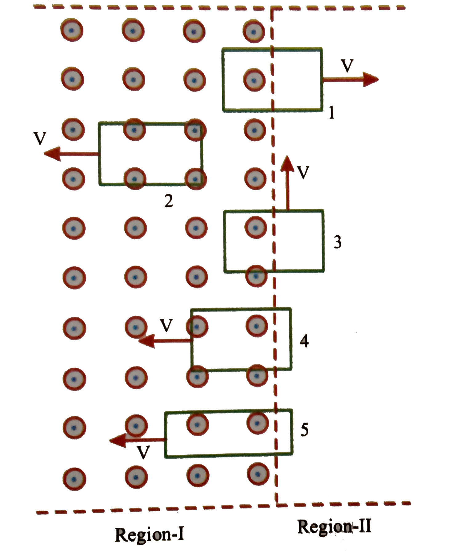
The corretc order of magnitudes of current in the loops is
View SolutionSix loops are formed of copper wire of the same cross-sectional area. Loops `1,2,3` and `4` are identical, loop `5` has the same area as the others but is longer. At the instant shown, all the loops are moving at the same speed in the directions indicated. A uniform and constant magnetic field points out of the page in region `I`, in region `II` there is no magnetic field. Ignore any interaction between the loops.
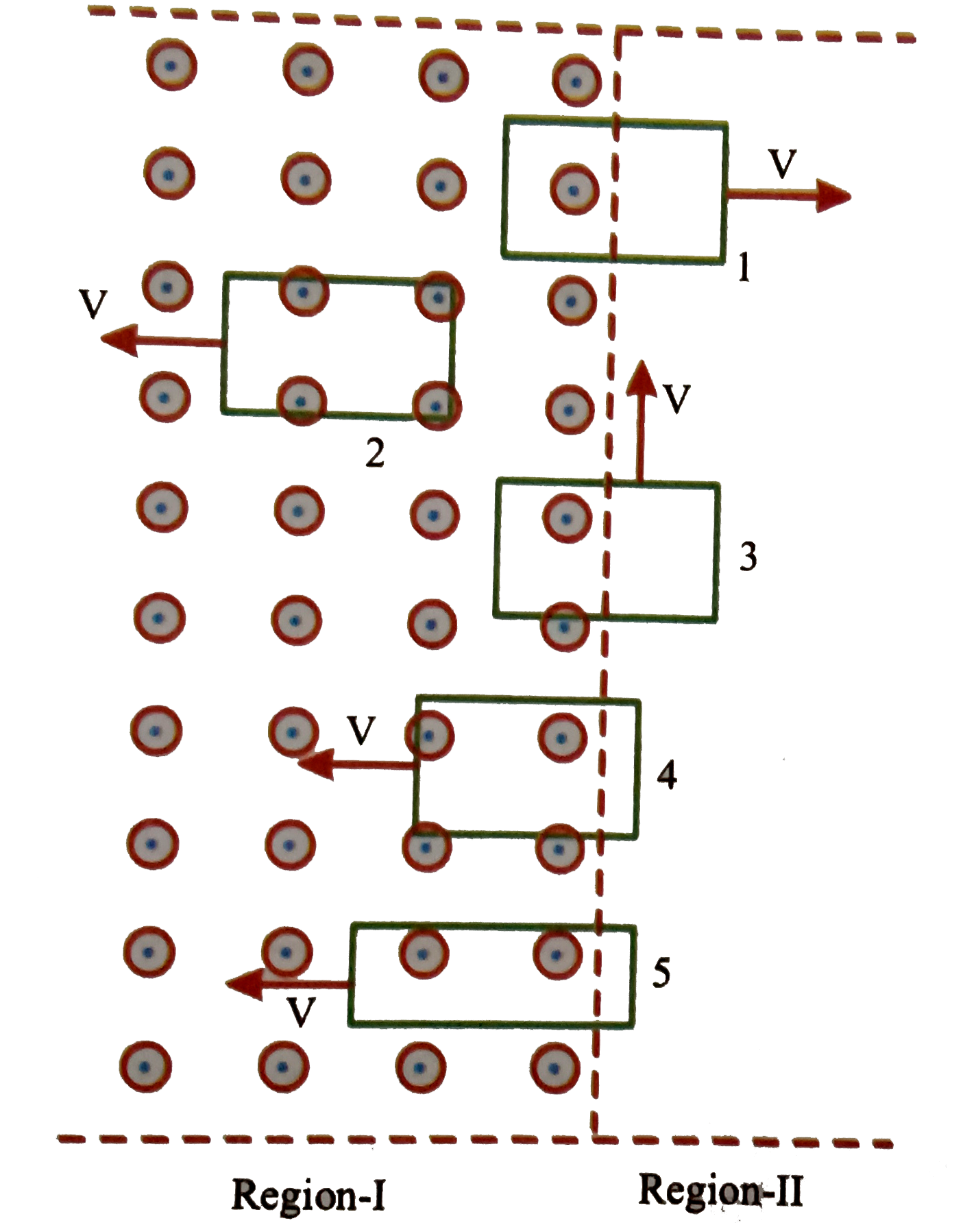
The correct order of magnitudes of emf induced in the loop is
View SolutionIn an `LR` circuit connected to a battery, the rate at which energy is stored in the inductor is plotted against time during the growth of current in the circuit. Which of the following best represents the resulting curve?
View SolutionIn the circuit shown in Fig. switch `k_(2)` is open and switch `k_(1)` is closed at `t = 0`. At time `t = t_(0)`, switch `k_(1)` is open and switch `k_(2)` is simultaneosuly closed. The variation of inductor current with time is
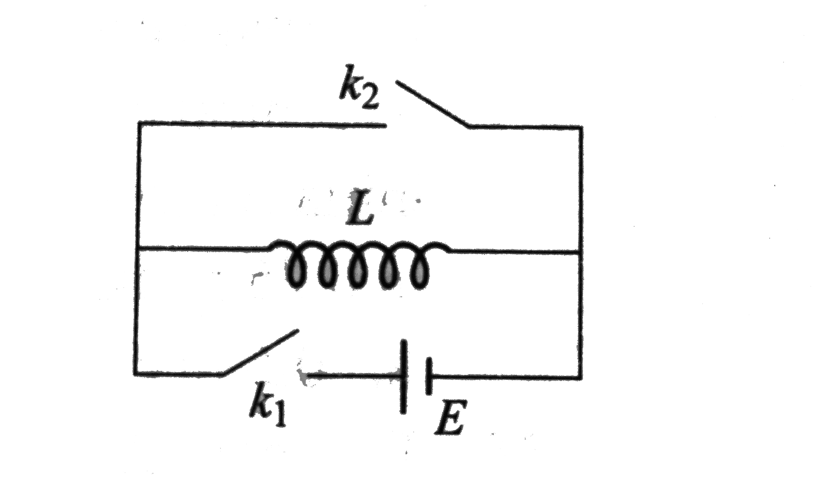
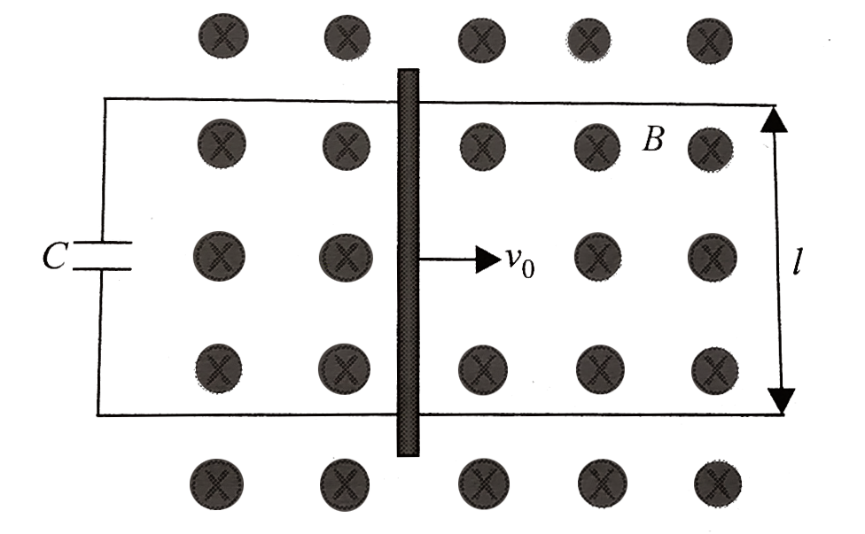
View SolutionTwo infinitely long conducting parallel rails are connected through a capacitor C as shown in Fig. A conductor of length l is moved with constant speed `v_(0)`. Which of the following graph truly depicts the variation of current through the conductor with time?
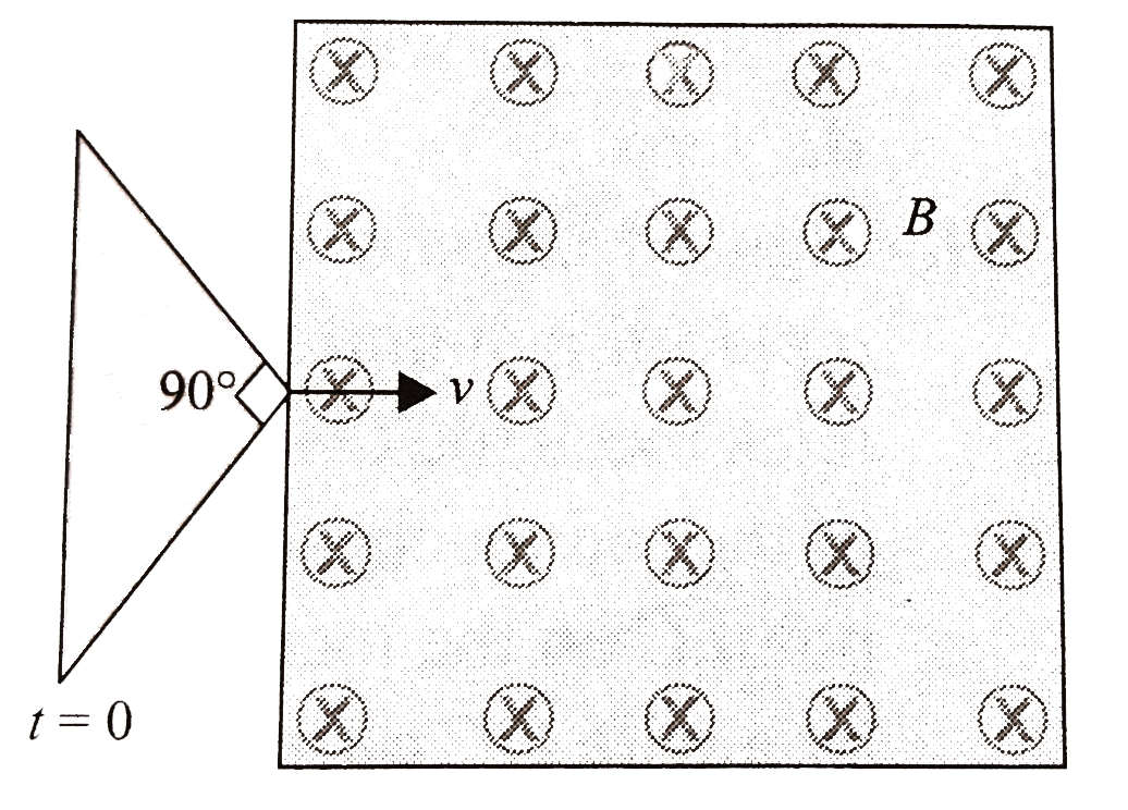
View SolutionFigure shows an isosceles triangle wire frame with apex angle equal to `(pi)//2`. The frame starts entering into the region of uniform magnetic field B with constant velocity v at t =0. The longest side of the frame is perpendicular to the direction of velocity. If i is the intantaneous current through the frame then choose the alternative showing the correct variation of i with time.
View Solution`A` and `B` are two coils placed closely as shown. The current in coil `A` varies as shown in the graph.
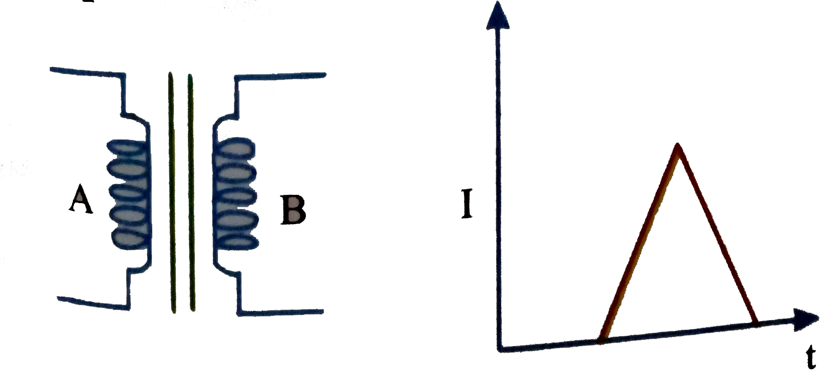
Then which of the following graphs gives the best respresent of variation of induction emf in coil `B`?
View Solution
Comprehension Type Questions questions and complete solutions for chapter ELECTRO MAGNETIC INDUCTION of NARAYANA PHYSICS (HINGLISH) of Class 12