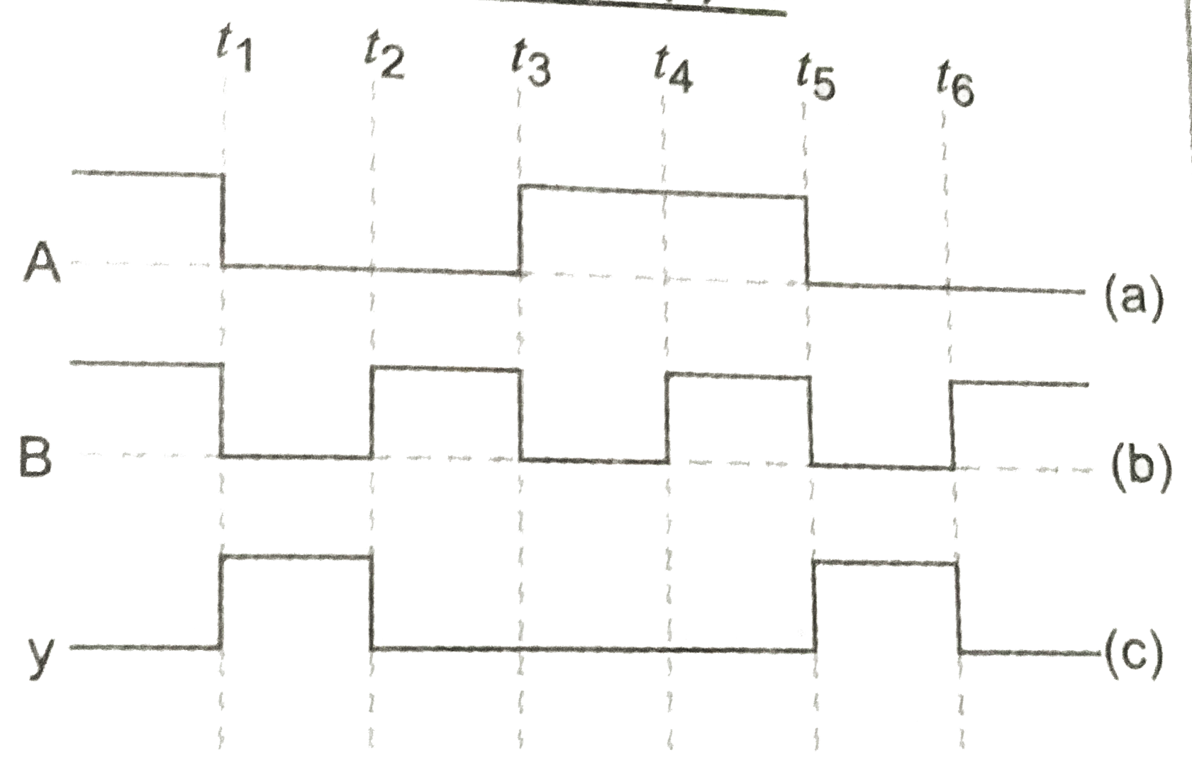
Consider the circuit given below
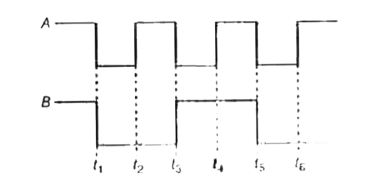
Chose the sketch depicting the output Y of this circuit having inputs A and B as given below

A

B

C

D

Text Solution
The correct Answer is:C
Truth table for the given diagram
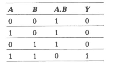
From 0 to
From to
From to
From to
From to
From to
|
Topper's Solved these Questions
Similar Questions
Knowledge Check
The ouput Y of the logic circuit given below is
 AA+BB¯¯¯AC¯¯¯¯¯¯¯¯¯¯¯¯¯¯A−B¯¯¯AD¯¯¯¯¯¯¯¯¯¯¯¯¯¯A−BA
The output of the given circuit in figure given below,
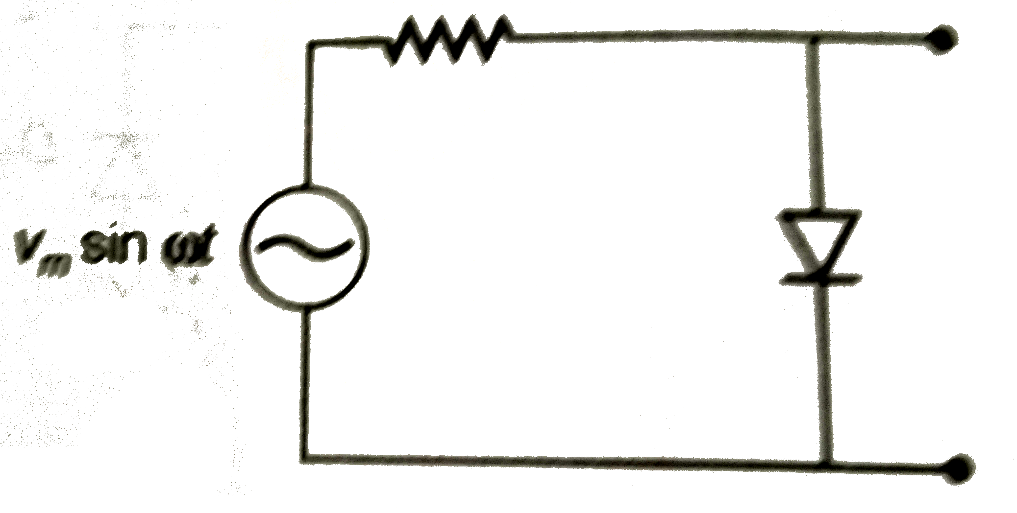 Awould be zero at all timesBwould be like a half wave rectifier with positive cycles in outputCwould be like a half wave rectifier with negative cycles in ouputDwould be like that of a full wave reactifier.
The output of the given circuit in figure given below,
 Awould be zero at all times.Bwould be like a half wave rectifier with positive cycles in outputCwould be like a half wave rectifier with negative cycles in output.Dwould be like that of a full wave rectifier.
The output Y of the logic circuit given below is
View SolutionThe output Y of the logic circuit given below is

View SolutionConsider the switching circuit given below :
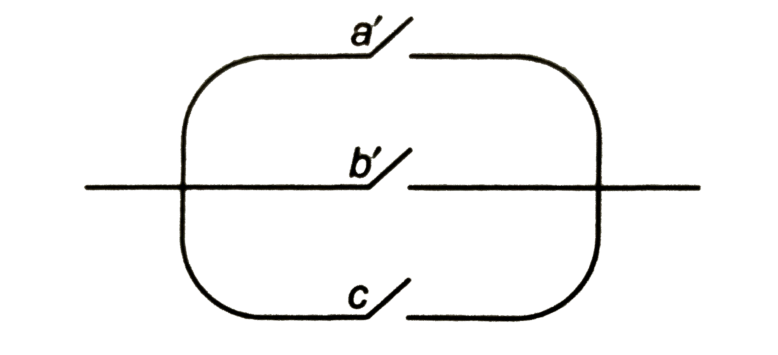
Then, the current flow in the circuit is
View SolutionConsider the switching circuit given below

Then, the current flow in the circuit is
View SolutionThe output of the given circuit in figure given below,

View Solution

