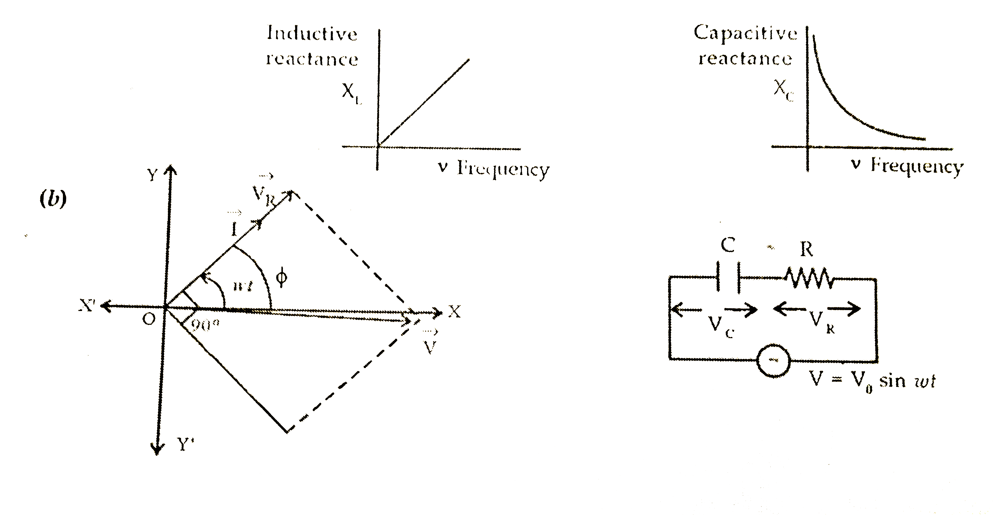
(a) Draw graphs showing the variations of inductive reactnace and capacitive reactance with frequency of the applied ac source .
(b) Draw the phasor diagram for a series RC circuit connected to an ac source.
(c ) An alternating voltage of 220 V is applied across a device X , a current of 0.25 A flows , which lag behind the applied voltage in phase by π2 radian . If the same voltage is applied across another device Y , the same current flows but now it is in phase with the applied voltage .
(i) Name the devices X and Y.
(ii) Calculate the current flowing in the circuit when the same voltage is applied across the series combination of X and Y.

(a) 
( c) (i) device is inductor . Y device is resistor.
(ii) 
XL=VI=2200.25 R=VI=2200.25
Hence XL=R=2200.25Ω
Now , they are connected in series
Z=√X2L+R2=√R2+R2=R√2

I=VZ=VR√2=200×0.25220√2=0.25√2=0.125√2A
Topper's Solved these Questions
- BOOK - XII BOARDS PREVIOUS YEARCHAPTER - XII BOARDSEXERCISE - SECTION - C13videos
XII BOARDS
- BOOK - XII BOARDS PREVIOUS YEARCHAPTER - XII BOARDSEXERCISE - SECTION - A7videos
XII BOARDS
- BOOK - XII BOARDS PREVIOUS YEARCHAPTER - XII BOARDSEXERCISE - SECTION - D6videos
XII BOARDS
- BOOK - XII BOARDS PREVIOUS YEARCHAPTER - SAMPLE PAPER 2019EXERCISE - SECTION D6videos
SAMPLE PAPER 2019
Similar Questions
Knowledge Check
- Question 1 - Select One
When an alternating voltage of 220V is applied across a device P, a current of 0.25A flows through the circuit and it leads the applied voltage by a angle π2 radian. When the same voltage source is connected across another device Q, the same current is observed in the circuit but in phase with the applied voltage. What is the current when the same source is connected across a series combination of P and Q?
A14√2 A lagging in phase by π4 with voltageB14√2 A leading in phase by π4 with voltageC1√2 A leading in phase by π4 with voltageD14√2 A leading in phase in π2 with voltage
Plot a graph showing variation of capacitive reactance with the change in the frequency of the AC source.
View SolutionWhen an alternating voltage of 220V is applied across a device P, a current of 0.25A flows through the circuit and it leads the applied voltage by a angle π2 radian. When the same voltage source is connected across another device Q, the same current is observed in the circuit but in phase with the applied voltage. What is the current when the same source is connected across a series combination of P and Q?
View SolutionWhen an alternating voltage of 220V is applied across a device P, a current of 0.25A flows through the circuit and it leads the applied voltage by a angle π2 radian. When the same voltage source is connected across another device Q, the same current is observed in the circuit but in phase with the applied voltage. What is the current when the same source is connected across a series combination of P and Q?
View Solution(i) Draw the graphs showing variation of inductive reactance and capacitive reactance with frequency of applied a.c. source.
(ii) Can the voltage drop across the inductor or the capacitor in a series LCR circuit be greater than the applied voltage of the a.c. source ? Justify your answer.View SolutionExplain the term 'inductive reactance'.Show graphically the variation of inductive reactance with frequency of the applied alternating voltage.
An a.c. voltage E=E0sinωt is applied across a pure inductor L.Show mathematically that the current flowing through it lags behind the applied voltage by a phase angle of π/2.View SolutionExplain the term 'inductive reactance'.Show graphically the variation of inductive reactance with frequency of the applied alternating voltage.
An a.c. voltage E=E0sinωt is applied across a pure inductor L.Show mathematically that the current flowing through it lags behind the applied voltage by a phase angle of π/2.View SolutionExplain the term 'capacitive reactance'.Show graphically the variation of capacitive reactance with frequency of the applied alternating voltage.
An a.c. voltage E=E0sinωt is applied a across a pure capacitor C.Show mathematically that the current flowing through it leads the applied voltage by a phase angle of π/2View Solution
